oil level YAMAHA NIKEN GT 2019 Owners Manual
[x] Cancel search | Manufacturer: YAMAHA, Model Year: 2019, Model line: NIKEN GT, Model: YAMAHA NIKEN GT 2019Pages: 108, PDF Size: 9.98 MB
Page 6 of 108

Table of contentsSafety information ............................ 1-1
Description ....................................... 2-1
Left view ......................................... 2-1
Right view ....................................... 2-2
Controls and instruments ............... 2-3
Instrument an d control functions ... 3-1
Immobilizer system......................... 3-1
Main switch/steering lock............... 3-2
Handlebar switches ........................ 3-3
Indicator lights and warning lights............................................ 3-5
Cruise control system..................... 3-8
Multi-function meter unit .............. 3-11
D-mode (drive mode).................... 3-19
Clutch lever .................................. 3-19
Shift pedal .................................... 3-20
Quick shift system ........................ 3-20
Brake lever.................................... 3-21
Brake pedal .................................. 3-21
ABS .............................................. 3-21
Traction control system ................ 3-22
Fuel tank cap ................................ 3-24
Fuel ............................................... 3-25
Fuel tank overflow hose ............... 3-27
Catalytic converter ....................... 3-27
Seats ............................................ 3-28
Helmet holding cable.................... 3-29
Storage compartment .................. 3-30
Rear view mirrors.......................... 3-31 Adjusting the front fork ................. 3-31
Adjusting the shock absorber
assembly.................................... 3-32
Auxiliary DC jacks ......................... 3-34
Sidestand ...................................... 3-35
Ignition circuit cut-off system ....... 3-35
For your safety – pre-operation
checks ............................................... 4-1
Operation an d important ri din g
points ................................................. 5-1
Starting the engine .......................... 5-1
Shifting ............................................ 5-2
Tips for reducing fuel consumption ................................ 5-4
Engine break-in ............................... 5-4
Parking ............................................ 5-5
Perio dic maintenance an d
a d justment ........................................ 6-1
Tool kit ............................................ 6-2
Periodic maintenance charts .......... 6-3
Periodic maintenance chart for the emission control system .............. 6-3
General maintenance and
lubrication chart ........................... 6-5
Removing and installing the panel ............................................ 6-9
Checking the spark plugs ............. 6-10
Canister ......................................... 6-11 Engine oil ...................................... 6-11
Why Yamalube.............................. 6-13
Coolant ......................................... 6-14
Air filter element ............................ 6-15
Checking the engine idling
speed ........................................ 6-15
Checking the throttle grip free play ............................................ 6-16
Valve clearance............................. 6-16
Tires .............................................. 6-16
Cast wheels .................................. 6-19
Adjusting the clutch lever free play ............................................ 6-19
Checking the brake lever free
play ............................................ 6-20
Brake light switches ..................... 6-20
Checking the front and rear brake pads ................................ 6-21
Checking the brake fluid level ...... 6-22
Changing the brake fluid .............. 6-23
Drive chain slack........................... 6-23
Cleaning and lubricating the drive chain ................................. 6-25
Checking and lubricating the cables ........................................ 6-25
Checking and lubricating the
throttle grip and cable ............... 6-26
Checking and lubricating the brake and shift pedals............... 6-26
Checking and lubricating the brake and clutch levers ............. 6-27UB5BE0E0.book Page 1 Friday, September 7, 2018 10:34 AM
Page 14 of 108
Description
2-2
2
EAU10421
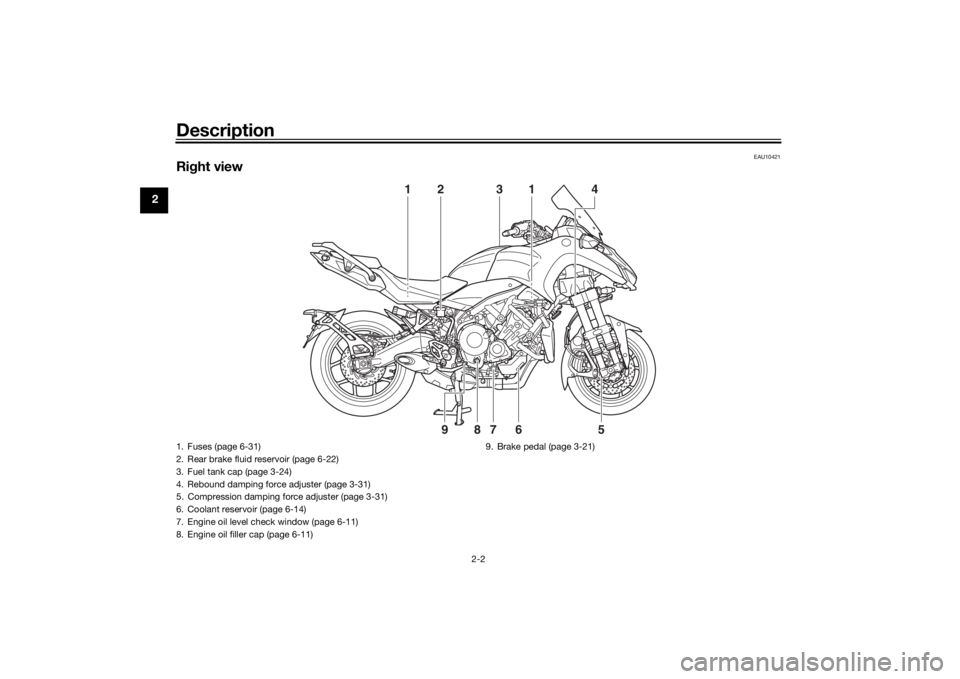
Right view
2
1
1
4
3
6
7
8
9
5
1. Fuses (page 6-31)
2. Rear brake fluid reservoir (page 6-22)
3. Fuel tank cap (page 3-24)
4. Rebound damping force adjuster (page 3-31)
5. Compression damping force adjuster (page 3-31)
6. Coolant reservoir (page 6-14)
7. Engine oil level check window (page 6-11)
8. Engine oil filler cap (page 6-11) 9. Brake pedal (page 3-21)UB5BE0E0.book Page 2 Friday, September 7, 2018 10:34 AM
Page 20 of 108
Instrument and control functions
3-5
3
EAU84530
“SELECT” switch
This switch is used to make setting
changes within the multi-function me-
ter unit. (See page 3-11.)
EAU84260
Drive mo de switch “MODE”
See page 3-19 for an explanation of
the drive mode.
EAU4939G
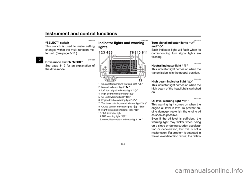
In dicator li ghts an d warnin g
li g hts
EAU11032
Turn si gnal in dicator li ghts “ ”
an d“”
Each indicator light will flash when its
corresponding turn signal lights are
flashing.
EAU11061
Neutral in dicator li ght “ ”
This indicator light comes on when the
transmission is in the neutral position.
EAU11081
Hi gh beam in dicator li ght “ ”
This indicator light comes on when the
high beam of the headlight is switched
on.
EAU11259
Oil level warnin g li ght “ ”
This warning light comes on when the
engine oil level is low. To prevent en-
gine damage, replenish the engine oil
as soon as possible.
Even if the oil level is sufficient, the
warning light may flicker when riding
on a slope or during sudden accelera-
tion or deceleration, but this is not a
malfunction. If a problem is detected in
the oil level detection circuit, the oil lev-
1. Coolant temperature warning light “ ”
2. Neutral indicator light “ ”
3. Left turn signal indicator light “ ”
4. High beam indicator light “ ”
5. Oil level warning light “ ”
6. Engine trouble warning light “ ”
7. Traction control system indicator light “ ”
8. Cruise control indicator lights “ ” “SET”
9. Right turn signal indicator light “ ”
10.Shift indicator light
11.ABS warning light “ ”
12.Immobilizer system indicator light “ ”123
654
118
910
78
12
ABS
UB5BE0E0.book Page 5 Friday, September 7, 2018 10:34 AM
Page 21 of 108
Instrument and control functions
3-6
3
el warning light will flash repeatedly. If
this occurs, have a Yamaha dealer
check the vehicle.
TIPWhen the vehicle is turned on, this light
will come on for a few seconds and
then go off. If the light does not come
on, or if the light remains on after con-
firming that the oil level is correct (see
page 6-11), have a Yamaha dealer
check the vehicle.
EAU58402
Cruise control in
dicator li ghts “ ”
an d “SET”
These indicator lights come on when
the cruise control system is activated.
(See page 3-8.)TIPWhen the vehicle is turned on, these
lights should come on for a few sec-
onds and then go off. If the lights do
not come on, have a Yamaha dealer
check the vehicle.
EAU11449
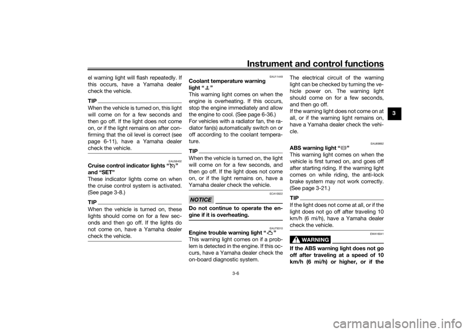
Coolant temperature warnin g
li g ht “ ”
This warning light comes on when the
engine is overheating. If this occurs,
stop the engine immediately and allow
the engine to cool. (See page 6-36.)
For vehicles with a radiator fan, the ra-
diator fan(s) automatically switch on or
off according to the coolant tempera-
ture.TIPWhen the vehicle is turned on, the light
will come on for a few seconds, and
then go off. If the light does not come
on, or if the light remains on, have a
Yamaha dealer check the vehicle. NOTICE
ECA10022
Do not continue to operate the en-
g ine if it is overheatin g.
EAU79310
En gine trou ble warnin g li ght “ ”
This warning light comes on if a prob-
lem is detected in the engine. If this oc-
curs, have a Yamaha dealer check the
on-board diagnostic system. The electrical circuit of the warning
light can be checked by turning the ve-
hicle power on. The warning light
should come on for a few seconds,
and then go off.
If the warning light does not come on at
all, or if the warning light remains on,
have a Yamaha dealer check the vehi-
cle.
EAU69892
ABS warnin
g lig ht “ ”
This warning light comes on when the
vehicle is first turned on, and goes off
after starting riding. If the warning light
comes on while riding, the anti-lock
brake system may not work correctly.
(See page 3-21.)TIPIf the light does not come at all, or if the
light does not go off after traveling 10
km/h (6 mi/h), have a Yamaha dealer
check the vehicle.
WARNING
EWA16041
If the ABS warning light does not go
off after travelin g at a speed of 10
km/h (6 mi/h) or hi gher, or if the
ABS
UB5BE0E0.book Page 6 Friday, September 7, 2018 10:34 AM
Page 52 of 108
For your safety – pre-operation checks
4-1
4
EAU15599
Inspect your vehicle each time you use it to make sure the vehicle is in safe operating condition. Always follow the inspection
and maintenance procedures and schedules described in the Owner’s Manual.
WARNING
EWA11152
Failure to inspect or maintain the vehicle properly increases the possibility of an acci dent or equipment damag e.
Do not operate the vehicle if you fin d any pro blem. If a pro blem cannot be corrected b y the proce dures provi ded in
this manual, have the vehicle inspecte d b y a Yamaha dealer.Before using this vehicle, check the following points:
ITEM CHECKS PAGE
Fuel • Check fuel level in fuel tank.
• Refuel if necessary.
• Check fuel line for leakage.
• Check fuel tank overflow hose for obstructions, cracks or damage, and check
hose connection. 3-25, 3-27
En gine oil • Check oil level in engine.
• If necessary, add recommended oil to specified level.
• Check vehicle for oil leakage. 6-11
Coolant • Check coolant level in reservoir.
• If necessary, add recommended coolant to specified level.
• Check cooling system for leakage. 6-14
Front brake • Check operation.
• If soft or spongy, have Yamaha dealer bleed hydraulic system.
• Check brake pads for wear.
• Replace if necessary.
• Check fluid level in reservoir.
• If necessary, add specified brake fluid to specified level.
• Check hydraulic system for leakage. 6-21, 6-22
UB5BE0E0.book Page 1 Friday, September 7, 2018 10:34 AM
Page 55 of 108
Operation and important ri din g points
5-1
5
EAU15952
Read the Owner’s Manual carefully to
become familiar with all controls. If
there is a control or function you do not
understand, ask your Yamaha dealer.
WARNING
EWA10272
Failure to familiarize yourself with
the controls can lead to loss of con-
trol, which coul d cause an acci dent
or injury.
EAUM3632
TIPThis model is equipped with: a lean angle sensor. This sensor
stops the engine in case of a vehi-
cle turnover. If this happens, the
engine trouble warning light will
come on, but this is not a malfunc-
tion. Turn the vehicle power off
and then back on again to cancel
the warning light. Failing to do so
will prevent the engine from start-
ing even though the engine will
crank when pushing the start
switch.
an engine auto-stop system. The
engine stops automatically if left
idling for 20 minutes. If the engine
stops, simply push the start
switch to restart the engine.
EAU84620
Startin g the en gineUnder normal conditions, shift the
transmission into neutral before start-
ing the engine. To start the engine with
the transmission in gear, the sidestand
must be up and the clutch lever pulled.
To start the engine1. Set the engine stop switch to “ ”.
2. Turn the main switch to “ ”.
3. Confirm the following lights per-
form a circuit check. Coolant temperature warning
light
Oil level warning light
Engine trouble warning light
ABS warning light
Traction control system indi-
cator light
Cruise control indicator lights
Shift indicator light
Immobilizer system indicator
lightTIP The ABS warning light should go
off after reaching a speed of 10
km/h (6 mi/h) or higher.
UB5BE0E0.book Page 1 Friday, September 7, 2018 10:34 AM
Page 66 of 108

Periodic maintenance an d a djustment
6-7
6
21 *Front fork • Check operation and for oil leak-
age.
• Replace if necessary. √√√√
22 *Shock a
bsor ber as-
sem bly • Check operation and for oil leak-
age.
• Replace if necessary. √√√√
23 *Rear suspension re-
lay arm an
d con-
nectin g arm
pivotin g points • Check operation.
√√√√
24 En gine oil • Change (warm engine before
draining).
• Check oil level and vehicle for oil leakage. √√√√√√
25 En
gine oil filter car-
tri dge • Replace.
√√√
26 *Coolin g system • Check coolant level and vehicle
for coolant leakage. √√√√√
• Change. Every 3 years
27 *Front an
d rear
b rake switches • Check operation.
√√√√√√
28 *Movin
g parts an d
cab les • Lubricate.
√√√√√
29 *Throttle
grip hous-
in g an d cab le • Check operation and free play.
• Adjust the throttle cable free play
if necessary.
• Lubricate the throttle grip hous- ing, cable and grip warmer wire. √√√√√
NO. ITEM CHECK OR MAINTENANCE JOB
ODOMETER READING
A
NNUAL
CHECK
1000 km
(600 mi) 10000 km
(6000 mi) 20000 km
(12000 mi) 30000 km
(18000 mi) 40000 km
(24000 mi)
UB5BE0E0.book Page 7 Friday, September 7, 2018 10:34 AM
Page 67 of 108
Periodic maintenance an d a djustment
6-8
6
EAU72800
TIP Air filter
• This model’s air filter is equipped with a disposable oil-coated paper element, which must not be cleaned with com- pressed air to avoid damaging it.
• The air filter element needs to be replaced more frequently when riding in unusually wet or dusty areas.
Hydraulic brake service
• Regularly check and, if necessary, correct the brake fluid level.
• Every two years replace the internal components of the brake master cylinders and calipers, and change the brake fluid.
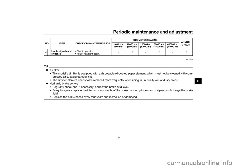
• Replace the brake hoses every four years and if cracked or damaged.30 *Li
ghts, si gnals an d
switches • Check operation.
• Adjust headlight beam.
√√√√√√
NO. ITEM CHECK OR MAINTENANCE JOB
ODOMETER READING
ANNUAL
CHECK
1000 km
(600 mi) 10000 km
(6000 mi) 20000 km
(12000 mi) 30000 km
(18000 mi) 40000 km
(24000 mi)
UB5BE0E0.book Page 8 Friday, September 7, 2018 10:34 AM
Page 70 of 108
Periodic maintenance an d a djustment
6-11
6
EAU36112
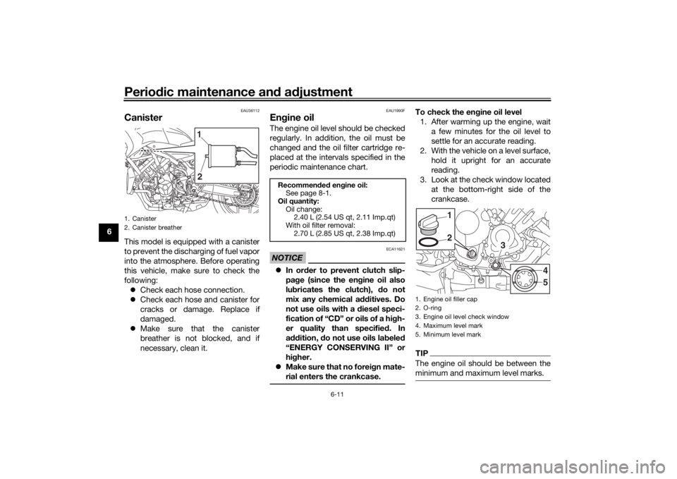
CanisterThis model is equipped with a canister
to prevent the discharging of fuel vapor
into the atmosphere. Before operating
this vehicle, make sure to check the
following:
Check each hose connection.
Check each hose and canister for
cracks or damage. Replace if
damaged.
Make sure that the canister
breather is not blocked, and if
necessary, clean it.
EAU1990F
Engine oilThe engine oil level should be checked
regularly. In addition, the oil must be
changed and the oil filter cartridge re-
placed at the intervals specified in the
periodic maintenance chart.NOTICE
ECA11621
In or der to prevent clutch slip-
pa ge (since the en gine oil also
lu bricates the clutch), do not
mix any chemical additives. Do
not use oils with a diesel speci-
fication of “CD” or oils of a hi gh-
er quality than specifie d. In
a ddition, do not use oils la beled
“ENERGY CONSERVING II” or
hi gher.
Make sure that no forei gn mate-
rial enters the crankcase.
To check the en gine oil level
1. After warming up the engine, wait a few minutes for the oil level to
settle for an accurate reading.
2. With the vehicle on a level surface, hold it upright for an accurate
reading.
3. Look at the check window located at the bottom-right side of the
crankcase.TIPThe engine oil should be between the
minimum and maximum level marks.
1. Canister
2. Canister breather
1
2
Recommen ded en gine oil:
See page 8-1.
Oil quantity: Oil change:2.40 L (2.54 US qt, 2.11 Imp.qt)
With oil filter removal: 2.70 L (2.85 US qt, 2.38 Imp.qt)
1. Engine oil filler cap
2. O-ring
3. Engine oil level check window
4. Maximum level mark
5. Minimum level mark
21
3
45
UB5BE0E0.book Page 11 Friday, September 7, 2018 10:34 AM
Page 71 of 108
Periodic maintenance an d a djustment
6-12
6
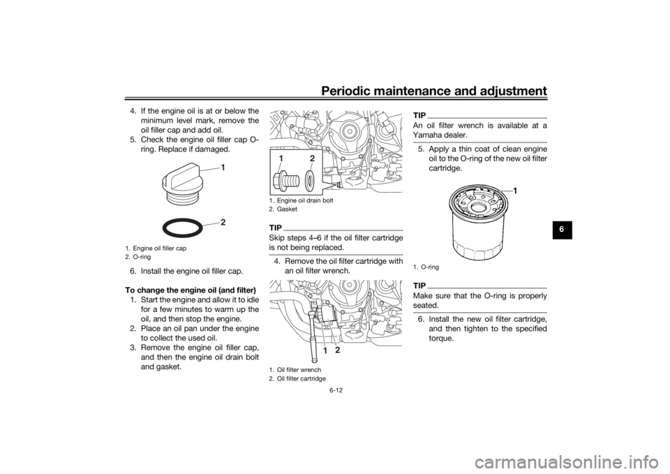
4. If the engine oil is at or below the
minimum level mark, remove the
oil filler cap and add oil.
5. Check the engine oil filler cap O- ring. Replace if damaged.
6. Install the engine oil filler cap.
To chan ge the en gine oil (an d filter)
1. Start the engine and allow it to idle for a few minutes to warm up the
oil, and then stop the engine.
2. Place an oil pan under the engine to collect the used oil.
3. Remove the engine oil filler cap, and then the engine oil drain bolt
and gasket.
TIPSkip steps 4–6 if the oil filter cartridge
is not being replaced.4. Remove the oil filter cartridge withan oil filter wrench.
TIPAn oil filter wrench is available at a
Yamaha dealer.5. Apply a thin coat of clean engineoil to the O-ring of the new oil filter
cartridge.TIPMake sure that the O-ring is properly
seated.6. Install the new oil filter cartridge,and then tighten to the specified
torque.
1. Engine oil filler cap
2. O-ring
21
1. Engine oil drain bolt
2. Gasket
1. Oil filter wrench
2. Oil filter cartridge
1
2
2
1
1. O-ring
UB5BE0E0.book Page 12 Friday, September 7, 2018 10:34 AM