ESP YAMAHA NIKEN GT 2020 Owners Manual
[x] Cancel search | Manufacturer: YAMAHA, Model Year: 2020, Model line: NIKEN GT, Model: YAMAHA NIKEN GT 2020Pages: 108, PDF Size: 9.92 MB
Page 8 of 108

1-1
1
Safety information
EAU84510
Be a Responsible Owner
As the vehicle’s owner, you are re-
sponsible for the safe and proper oper-
ation of your motorcycle.
This is a leaning multi-wheel motorcy-
cle.
The safe use and operation of this mo-
torcycle is dependent upon the use of
proper riding techniques as well as the
expertise of the operator. Every opera-
tor should know the following require-
ments before riding this motorcycle.
He or she should: Obtain thorough instructions from
a competent source on all aspects
of motorcycle operation.
Observe the warnings and mainte-
nance requirements in this Own-
er’s Manual.
Obtain qualified training in safe
and proper riding techniques.
Obtain professional technical ser-
vice as indicated in this Owner’s
Manual and when made neces-
sary by mechanical conditions.
Never operate a motorcycle with-
out proper training or instruction.
Take a training course. Beginners
should receive training from a cer-
tified instructor. Contact an autho-
rized motorcycle dealer to find out
about the training courses nearest
you.
Safe Ri din g
Perform the pre-operation checks
each time you use the vehicle to make
sure it is in safe operating condition.
Failure to inspect or maintain the vehi-
cle properly increases the possibility of
an accident or equipment damage.
See page 4-1 for a list of pre-operation
checks. This motorcycle is designed to
carry the operator and a passen-
ger.
The failure of motorists to detect
and recognize motorcycles in traf-
fic is the predominating cause of
automobile-and-motorcycle acci-
dents. Many accidents have been
caused by an automobile driver
who did not see the motorcycle.
Making yourself conspicuous ap- pears to be very effective in reduc-
ing the chance of this type of
accident.
Therefore:
• Wear a brightly colored jacket.
• Use extra caution when you are approaching and passing
through intersections, since in-
tersections are the most likely
places for motorcycle accidents
to occur.
• Ride where other motorists can see you. Avoid riding in another
motorist’s blind spot.
• Never maintain a motorcycle without proper knowledge.
Contact an authorized motorcy-
cle dealer to inform you on ba-
sic motorcycle maintenance.
Certain maintenance can only
be carried out by certified staff.UB5BE1E0.book Page 1 Wednesday, October 30, 2019 9:59 AM
Page 11 of 108

Safety information
1-4
1
tents, can create unstable han-
dling or a slow steering re-
sponse.
This vehicle is not desi gne d to
pull a trailer or to be attached to
a si decar.
Genuine Yamaha Accessories
Choosing accessories for your vehicle
is an important decision. Genuine
Yamaha accessories, which are avail- able only from a Yamaha dealer, have
been designed, tested, and approved
by Yamaha for use on your vehicle.
Many companies with no connection
to Yamaha manufacture parts and ac-
cessories or offer other modifications
for Yamaha vehicles. Yamaha is not in
a position to test the products that
these aftermarket companies produce.
Therefore, Yamaha can neither en-
dorse nor recommend the use of ac-
cessories not sold by Yamaha or
modifications not specifically recom-
mended by Yamaha, even if sold and
installed by a Yamaha dealer. Aftermarket Parts, Accessories, an
d
Mo difications
While you may find aftermarket prod-
ucts similar in design and quality to
genuine Yamaha accessories, recog-
nize that some aftermarket accesso-
ries or modifications are not suitable
because of potential safety hazards to
you or others. Installing aftermarket
products or having other modifications
performed to your vehicle that change
any of the vehicle’s design or operation
characteristics can put you and others
at greater risk of serious injury or
death. You are responsible for injuries
related to changes in the vehicle.
Keep the following guidelines in mind,
as well as those provided on page 1-3
when mounting accessories. Never install accessories or carry
cargo that would impair the per-
formance of your motorcycle.
Carefully inspect the accessory
before using it to make sure that it
does not in any way reduce
ground clearance or cornering
clearance, limit suspension travel, steering travel or control opera-
tion, or obscure lights or reflec-
tors.
• Accessories fitted to the han- dlebar or the front fork area can
create instability due to improp-
er weight distribution or aerody-
namic changes. If accessories
are added to the handlebar or
front fork area, they must be as
lightweight as possible and
should be kept to a minimum.
• Bulky or large accessories may seriously affect the stability of
the motorcycle due to aerody-
namic effects. Wind may at-
tempt to lift the motorcycle, or
the motorcycle may become
unstable in cross winds. These
accessories may also cause in-
stability when passing or being
passed by large vehicles.
• Certain accessories can dis- place the operator from his or
her normal riding position. This
improper position limits the
freedom of movement of the
UB5BE1E0.book Page 4 Wednesday, October 30, 2019 9:59 AM
Page 20 of 108
Instrument and control functions
3-5
3
EAU84530
“SELECT” switch
This switch is used to make setting
changes within the multi-function me-
ter unit. (See page 3-11.)
EAU84260
Drive mo de switch “MODE”
See page 3-18 for an explanation of
the drive mode.
EAU4939J
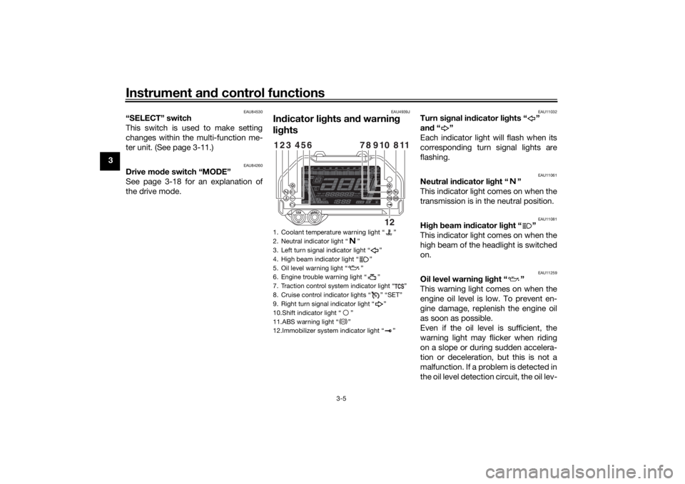
In dicator li ghts an d warnin g
li g hts
EAU11032
Turn si gnal in dicator li ghts “ ”
an d“”
Each indicator light will flash when its
corresponding turn signal lights are
flashing.
EAU11061
Neutral in dicator li ght “ ”
This indicator light comes on when the
transmission is in the neutral position.
EAU11081
Hi gh beam in dicator li ght “ ”
This indicator light comes on when the
high beam of the headlight is switched
on.
EAU11259
Oil level warnin g li ght “ ”
This warning light comes on when the
engine oil level is low. To prevent en-
gine damage, replenish the engine oil
as soon as possible.
Even if the oil level is sufficient, the
warning light may flicker when riding
on a slope or during sudden accelera-
tion or deceleration, but this is not a
malfunction. If a problem is detected in
the oil level detection circuit, the oil lev-
1. Coolant temperature warning light “ ”
2. Neutral indicator light “ ”
3. Left turn signal indicator light “ ”
4. High beam indicator light “ ”
5. Oil level warning light “ ”
6. Engine trouble warning light “ ”
7. Traction control system indicator light “ ”
8. Cruise control indicator lights “ ” “SET”
9. Right turn signal indicator light “ ”
10.Shift indicator light “ ”
11.ABS warning light “ ”
12.Immobilizer system indicator light “ ”123
654
118
910
78
12
ABS
UB5BE1E0.book Page 5 Wednesday, October 30, 2019 9:59 AM
Page 34 of 108
Instrument and control functions
3-19
3 MODE 3
This mode offers response that is
somewhat less sharp compared to
MODE 2 for riding situations that re-
quire especially sensitive throttle oper-
ation.
MODE 2
This mode is suitable for various riding
conditions.
This mode allows the rider to enjoy
smooth and sporty drivability from the
low-speed range to the high-speed
range.
MODE 1
This mode offers a sportier engine re-
sponse in the low- to mid-speed range
compared to MODE 2.
TIPThe current drive mode is saved when
the vehicle is turned off.
EAU12823
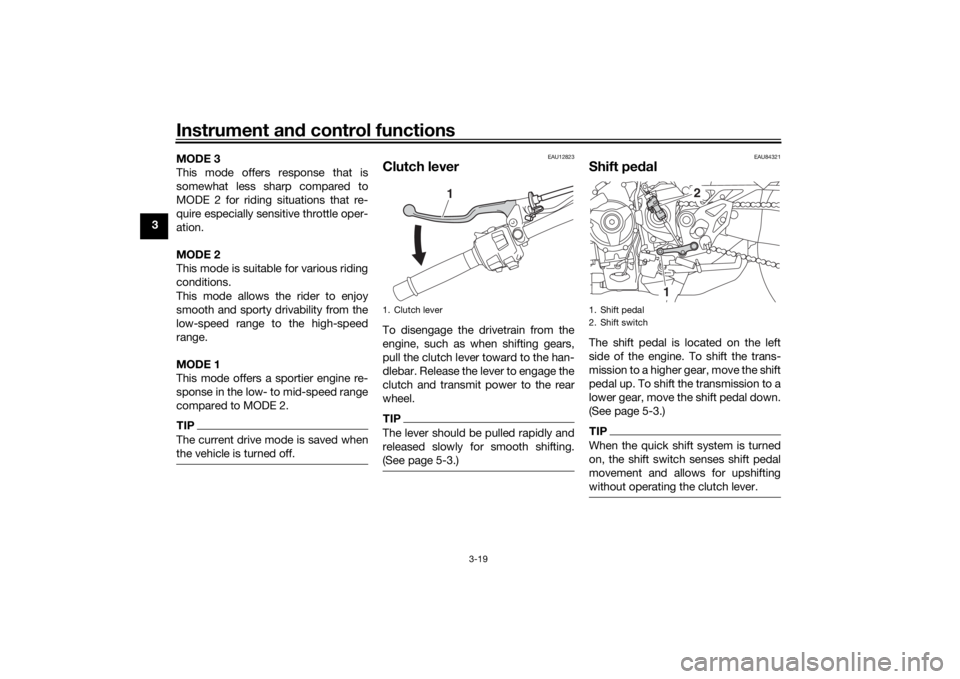
Clutch leverTo disengage the drivetrain from the
engine, such as when shifting gears,
pull the clutch lever toward to the han-
dlebar. Release the lever to engage the
clutch and transmit power to the rear
wheel.TIPThe lever should be pulled rapidly and
released slowly for smooth shifting.
(See page 5-3.)
EAU84321
Shift pe
dalThe shift pedal is located on the left
side of the engine. To shift the trans-
mission to a higher gear, move the shift
pedal up. To shift the transmission to a
lower gear, move the shift pedal down.
(See page 5-3.)TIPWhen the quick shift system is turned
on, the shift switch senses shift pedal
movement and allows for upshifting
without operating the clutch lever.
1. Clutch lever
1
1. Shift pedal
2. Shift switch
2
1
UB5BE1E0.book Page 19 Wednesday, October 30, 2019 9:59 AM
Page 37 of 108
Instrument and control functions
3-22
3
EAU76317
Traction control systemThe traction control system (TCS)
helps maintain traction when acceler-
ating on slippery surfaces, such as un-
paved or wet roads. If sensors detect
that the rear wheel is starting to slip
(uncontrolled spinning), the traction
control system assists by regulating
engine power as needed until traction
is restored.
WARNING
EWA15433
The traction control system is not a
su bstitute for ri din g appropriately
for the con ditions. Traction control
cannot prevent loss of traction d ue
to excessive spee d when enterin g
turns, when acceleratin g har d at a
sharp lean an gle, or while brakin g,
an d cannot prevent front wheel slip-
pin g. As with any vehicle, approach
surfaces that may be slippery with
caution an d avoi d especially slip-
pery surfaces.
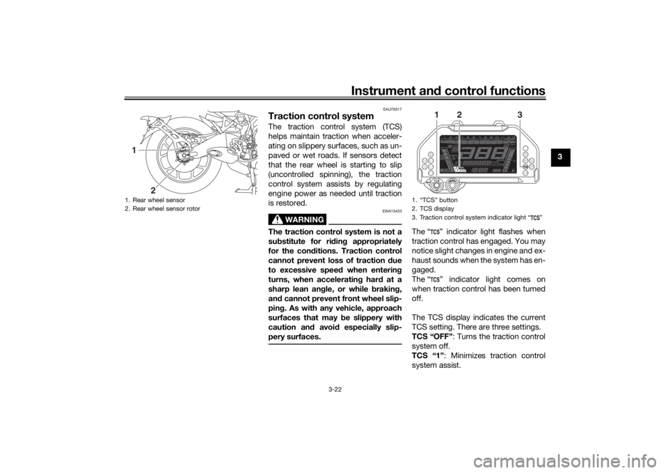
The “ ” indicator light flashes when
traction control has engaged. You may
notice slight changes in engine and ex-
haust sounds when the system has en-
gaged.
The “ ” indicator light comes on
when traction control has been turned
off.
The TCS display indicates the current
TCS setting. There are three settings.
TCS “OFF” : Turns the traction control
system off.
TCS “1” : Minimizes traction control
system assist.
1. Rear wheel sensor
2. Rear wheel sensor rotor1
2
1. “TCS” button
2. TCS display
3. Traction control system indicator light “ ”
1
3
2
UB5BE1E0.book Page 22 Wednesday, October 30, 2019 9:59 AM
Page 49 of 108
Instrument and control functions
3-34
3
NOTICE
ECA26610
Do not draw power from a DC jack
with the en gine turne d off. Do not
connect any accessory which uses
more than 12 W (1.0 A). Otherwise
the battery may d ischarge or a fuse
may blow.To use an auxiliary DC jack
1. Start the engine. (See page 5-2.)
2. Turn the accessory off.
3. Open the auxiliary DC jack cap.
4. Insert the accessory power plug.
5. Turn the accessory on.TIP When inserting or removing the
accessory power plug, turn the
accessory off.
When the auxiliary DC jack is not
being used, cover it with the cap.
WARNING
EWA14361
To prevent electrical shock or short-
circuitin g, make sure that the cap is
installe d when the auxiliary DC jack
is not bein g use d.
EAU15306
Si destan dThe sidestand is located on the left
side of the frame. Raise the sidestand
or lower it with your foot while holding
the vehicle upright.TIPThe built-in sidestand switch is part of
the ignition circuit cut-off system,
which cuts the ignition in certain situa-
tions. (See the following section for an
explanation of the ignition circuit cut-
off system.)
WARNING
EWA10242
The vehicle must not b e ridden with
the si destan d d own, or if the si de-
stan d cannot b e properly move d up
(or does not stay up), otherwise the
si destan d coul d contact the groun d
an d d istract the operator, resultin g
in a possib le loss of control.
Yamaha’s ig nition circuit cut-off
system has been desi gne d to assist
the operator in fulfillin g the respon-
si bility of raisin g the si destan d b e-
fore startin g off. Therefore, check this system re
gularly an d have a
Yamaha dealer repair it if it does not
function properly.
UB5BE1E0.book Page 34 Wednesday, October 30, 2019 9:59 AM
Page 84 of 108
Periodic maintenance an d a djustment
6-25
6
EAU23026
Cleanin g an d lu bricatin g the
d rive chainThe drive chain must be cleaned and
lubricated at the intervals specified in
the periodic maintenance and lubrica-
tion chart, otherwise it will quickly wear
out, especially when riding in dusty or
wet areas. Service the drive chain as
follows.NOTICE
ECA10584
The drive chain must b e lubricated
after washin g the motorcycle, ri din g
in the rain or ri din g in wet areas.1. Clean the drive chain with kero-
sene and a small soft brush.
NOTICE: To prevent d amaging
the O-rin gs, do not clean the
d rive chain with steam cleaners,
hi gh-pressure washers or inap-
propriate solvents.
[ECA11122]
2. Wipe the drive chain dry.
3. Thoroughly lubricate the drive chain with a special O-ring chain
lubricant. NOTICE: Do not use
en gine oil or any other lu bri-
cants for the drive chain, as they may contain su
bstances that
coul d damag e the O-rin gs.
[ECA11112] EAU23098
Checkin
g an d lu bricatin g the
cab lesThe operation of all control cables and
the condition of the cables should be
checked before each ride, and the ca-
bles and cable ends should be lubri-
cated if necessary. If a cable is
damaged or does not move smoothly,
have a Yamaha dealer check or re-
place it. WARNING! Dama ge to the
outer housin g of cab les may result
in internal rustin g an d cause inter-
ference with cab le movement. Re-
place damag ed cab les as soon as
possi ble to prevent unsafe con di-
tions.
[EWA10712]
Recommen ded lu bricant:
Yamaha cable lubricant or other
suitable cable lubricant
UB5BE1E0.book Page 25 Wednesday, October 30, 2019 9:59 AM
Page 96 of 108
Motorcycle care and stora ge
7-1
7
EAU37834
Matte color cautionNOTICE
ECA15193
Some mo dels are equipped with
matte colore d finishe d parts. Be
sure to consult a Yamaha d ealer for
a d vice on what prod ucts to use be-
fore cleanin g the vehicle. Usin g a
b rush, harsh chemical prod ucts or
cleanin g compoun ds when cleanin g
these parts will scratch or damag e
their surface. Wax also shoul d not
b e applied to any matte colore d fin-
ishe d parts.
EAU83443
CareFrequent, thorough cleaning of the ve-
hicle will not only enhance its appear-
ance but also will improve its general
performance and extend the useful life
of many components. Washing, clean-
ing, and polishing will also give you a
chance to inspect the condition of the
vehicle more frequently. Be sure to
wash the vehicle after riding in the rain
or near the sea, because salt is corro-
sive to metals.TIP The roads of heavy snowfall areas
may be sprayed with salt as a de-
icing method. This salt can stay on
the roads well into spring, so be
sure to wash the underside and
chassis parts after riding in such
areas.
Genuine Yamaha care and main-
tenance products are sold under
the YAMALUBE brand in many
markets worldwide.
See your Yamaha dealer for addi-
tional cleaning tips.
NOTICE
ECA26280
Improper cleanin g can cause cos-
metic an d mechanical damag e. Do
not use: high-pressure washers or
steam-jet cleaners. Excessive
water pressure may cause wa-
ter seepa ge an d d eterioration of
wheel bearin gs, brakes, trans-
mission seals an d electrical d e-
vices. Avoi d hi gh-pressure
d eter gent applications such as
those availa ble in coin-operate d
car washers.
harsh chemicals, inclu din g
stron g aci dic wheel cleaners,
especially on spoke or ma gne-
sium wheels.
harsh chemicals, ab rasive
cleanin g compoun ds, or wax on
matte-finishe d parts. Brushes
can scratch an d damag e the
matte-finish, use soft spon ge or
towel only.
towels, spon ges, or brushes
contaminated with abrasive
cleanin g prod ucts or stron g
UB5BE1E0.book Page 1 Wednesday, October 30, 2019 9:59 AM