brake YAMAHA NMAX 125 2015 Owners Manual
[x] Cancel search | Manufacturer: YAMAHA, Model Year: 2015, Model line: NMAX 125, Model: YAMAHA NMAX 125 2015Pages: 90, PDF Size: 3.56 MB
Page 6 of 90

Table of contentsSafety information ............................ 1-1
Further safe-riding points ............... 1-5
Description ....................................... 2-1
Left view ......................................... 2-1
Right view ....................................... 2-2
Controls and instruments ............... 2-3
Instrument an d control functions ... 3-1
Main switch/steering lock............... 3-1
Keyhole shutter .............................. 3-2
Indicator lights and warning lights............................................ 3-2
Multi-function meter unit ................ 3-4
Handlebar switches ...................... 3-10
Front brake lever .......................... 3-10
Rear brake lever ........................... 3-11
ABS .............................................. 3-11
Fuel tank cap ................................ 3-12
Fuel ............................................... 3-13
Fuel tank overflow hose ............... 3-14
Catalytic converter ....................... 3-14
Seat .............................................. 3-15
Storage compartments................. 3-16
Sidestand ..................................... 3-17
Ignition circuit cut-off system ....... 3-17 For your safety – pre-operation
checks
............................................... 4-1
Operation an d important ri din g
points ................................................. 5-1
Starting the engine .......................... 5-1
Starting off ...................................... 5-2
Acceleration and deceleration ........ 5-2
Braking ............................................ 5-2
Tips for reducing fuel consumption ................................ 5-3
Engine break-in ............................... 5-3
Parking ............................................ 5-4
Perio dic maintenance an d
a d justment ........................................ 6-1
Owner’s tool kit ............................... 6-1
Periodic maintenance chart for
the emission control system ........ 6-2
General maintenance and
lubrication chart ........................... 6-3
Removing and installing panels ...... 6-7
Checking the spark plug ................. 6-8
Engine oil and oil strainer .............. 6-10
Final transmission oil..................... 6-12
Coolant.......................................... 6-13
Air filter and V-belt case air filter elements .................................... 6-16
Checking the throttle grip
free play ..................................... 6-18
Valve clearance ............................. 6-19 Tires .............................................. 6-19
Cast wheels .................................. 6-21
Checking the front and rear
brake lever free play .................. 6-21
Checking the front and rear
brake pads ................................ 6-22
Checking the brake fluid level ...... 6-22
Changing the brake fluid .............. 6-24
Checking the V-belt ...................... 6-24
Checking and lubricating the cables ........................................ 6-24
Checking and lubricating the throttle grip and cable ............... 6-25
Lubricating the front and rear
brake levers ............................... 6-25
Checking and lubricating the centerstand and sidestand........ 6-26
Checking the front fork ................. 6-26
Checking the steering................... 6-27
Checking the wheel bearings ....... 6-27
Battery .......................................... 6-28
Replacing the fuses ...................... 6-29
Headlight ...................................... 6-30
Replacing an auxiliary light bulb ........................................... 6-31
Brake light..................................... 6-32
Replacing the taillight bulb ........... 6-32
Replacing a front turn signal light bulb.................................... 6-34
Replacing a rear turn signal light bulb.................................... 6-35U2DSE0E0.book Page 1 Thursday, March 19, 2015 10:34 AM
Page 12 of 90

Safety information
1-5
1Aftermarket Tires an
d Rims
The tires and rims that came with your
scooter were designed to match the
performance capabilities and to pro-
vide the best combination of handling,
braking, and comfort. Other tires, rims,
sizes, and combinations may not be
appropriate. Refer to page 6-19 for tire
specifications and more information on
replacing your tires.
Transportin g the Scooter
Be sure to observe following instruc-
tions before transporting the scooter in
another vehicle. Remove all loose items from the
scooter.
Point the front wheel straight
ahead on the trailer or in the truck
bed, and choke it in a rail to pre-
vent movement.
Secure the scooter with tie-downs
or suitable straps that are at-
tached to solid parts of the scoot-
er, such as the frame or upper
front fork triple clamp (and not, for
example, to rubber-mounted han-
dlebars or turn signals, or parts
that could break). Choose the lo- cation for the straps carefully so
the straps will not rub against
painted surfaces during transport.
The suspension should be com-
pressed somewhat by the tie-
downs, if possible, so that the
scooter will not bounce exces-
sively during transport.
EAU57600
Further safe-ri din g points Be sure to signal clearly when
making turns.
Braking can be extremely difficult
on a wet road. Avoid hard braking,
because the scooter could slide.
Apply the brakes slowly when
stopping on a wet surface.
Slow down as you approach a
corner or turn. Once you have
completed a turn, accelerate
slowly.
Be careful when passing parked
cars. A driver might not see you
and open a door in your path.
Railroad crossings, streetcar rails,
iron plates on road construction
sites, and manhole covers be-
come extremely slippery when
wet. Slow down and cross them
with caution. Keep the scooter up-
right, otherwise it could slide out
from under you.
The brake pads or linings could
get wet when you wash the scoot-
er. After washing the scooter,
check the brakes before riding.
U2DSE0E0.book Page 5 Thursday, March 19, 2015 10:34 AM
Page 15 of 90

Description
2-2
2
EAU10421
Right view
1 2,34
567
8
9
1. Tail/brake light (page 6-32)
2. Battery (page 6-28)
3. Fuse box (page 6-29)
4. Headlight (page 6-30)
5. Coolant reservoir (page 6-13)
6. Spark plug (page 6-8)
7. Coolant drain screw (page 6-14)
8. Engine oil filler cap (page 6-10) 9. Radiator cap (page 6-13)
U2DSE0E0.book Page 2 Thursday, March 19, 2015 10:34 AM
Page 16 of 90
Description
2-3
2
EAU10431
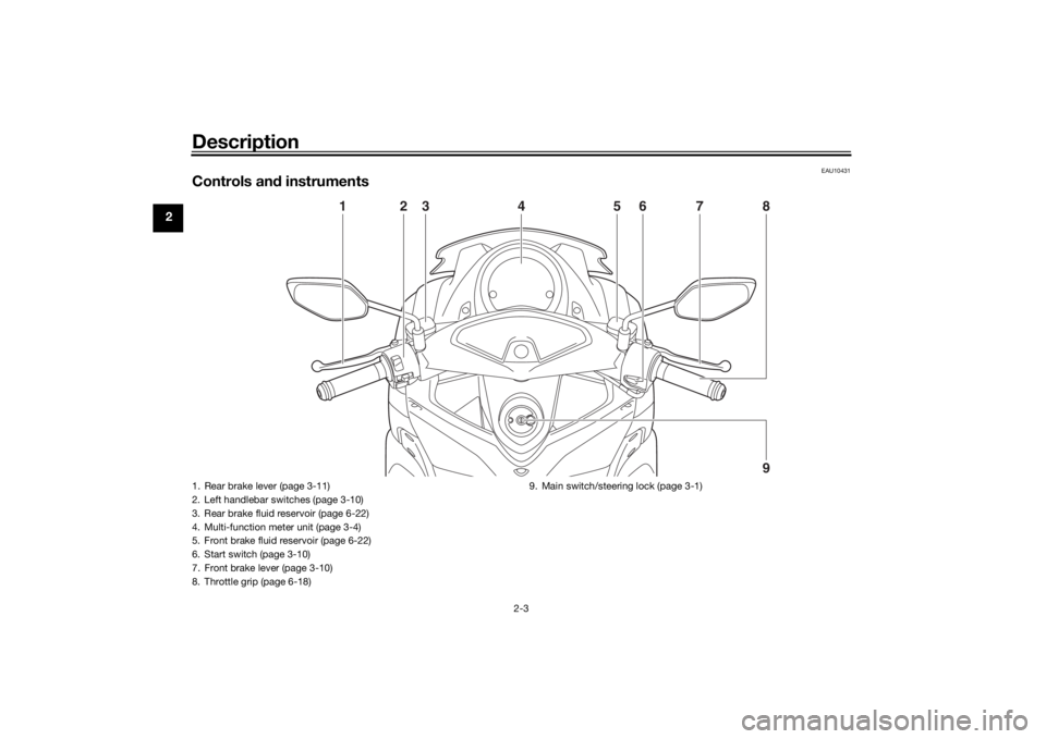
Controls and instruments
1
2
3
7
6
8
5
4
9
1. Rear brake lever (page 3-11)
2. Left handlebar switches (page 3-10)
3. Rear brake fluid reservoir (page 6-22)
4. Multi-function meter unit (page 3-4)
5. Front brake fluid reservoir (page 6-22)
6. Start switch (page 3-10)
7. Front brake lever (page 3-10)
8. Throttle grip (page 6-18) 9. Main switch/steering lock (page 3-1)U2DSE0E0.book Page 3 Thursday, March 19, 2015 10:34 AM
Page 18 of 90
Instrument and control functions
3-2
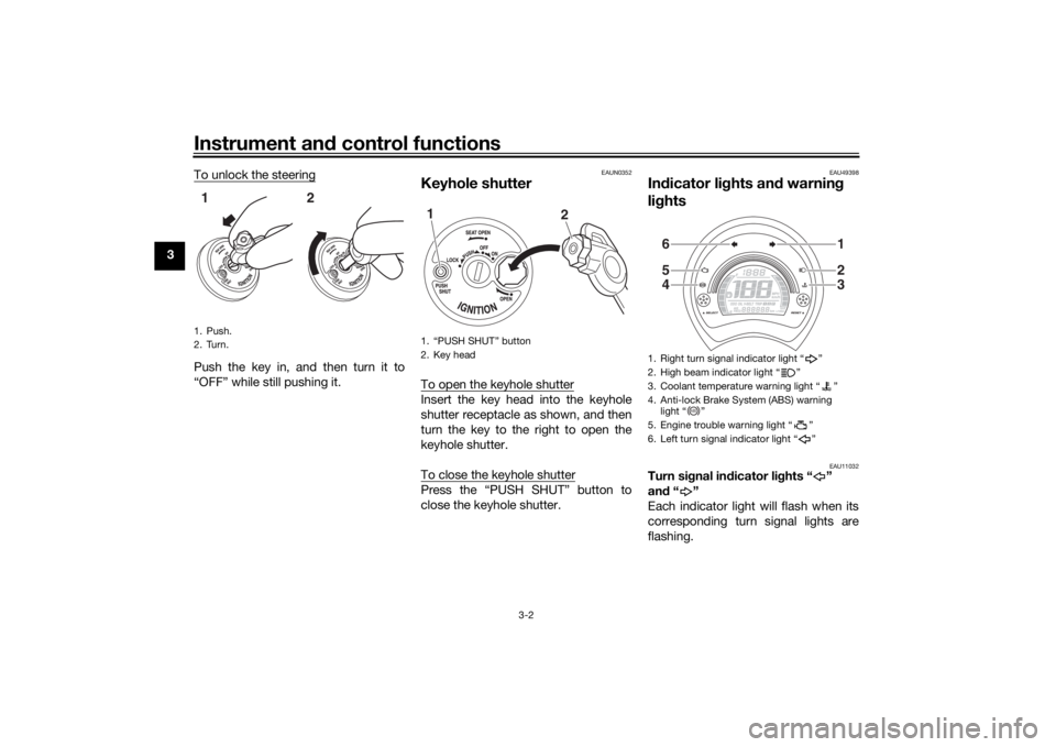
3 To unlock the steering
Push the key in, and then turn it to
“OFF” while still pushing it.
EAUN0352
Keyhole shutterTo open the keyhole shutterInsert the key head into the keyhole
shutter receptacle as shown, and then
turn the key to the right to open the
keyhole shutter.
To close the keyhole shutterPress the “PUSH SHUT” button to
close the keyhole shutter.
EAU49398
In
dicator li ghts an d warnin g
li g hts
EAU11032
Turn si gnal in dicator li ghts “ ”
an d“”
Each indicator light will flash when its
corresponding turn signal lights are
flashing.
1. Push.
2. Turn.12
1. “PUSH SHUT” button
2. Key head1
2
1. Right turn signal indicator light “ ”
2. High beam indicator light “ ”
3. Coolant temperature warning light “ ”
4. Anti-lock Brake System (ABS) warning light “ ”
5. Engine trouble warning light “ ”
6. Left turn signal indicator light “ ”
654
123
ABS
U2DSE0E0.book Page 2 Thursday, March 19, 2015 10:34 AM
Page 20 of 90
Instrument and control functions
3-4
3 b
le wheel lock during emer gency
b rakin g. Have a Yamaha d ealer
check the brake system an d electri-
cal circuits as soon as possi ble.
TIPThe ABS warning light may come on
while accelerating the engine with the
vehicle on its centerstand, but this
does not indicate a malfunction.
EAUN0981
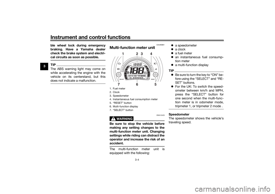
Multi-function meter unit
WARNING
EWA12423
Be sure to stop the vehicle before
makin g any settin g chan ges to the
multi-function meter unit. Chan gin g
settin gs while ri din g can d istract the
operator an d increase the risk of an
acci dent.The multi-function meter unit is
equipped with the following:
a speedometer
a clock
a fuel meter
an instantaneous fuel consump-
tion meter
a multi-function display
TIPBe sure to turn the key to “ON” be-
fore using the “SELECT” and “RE-
SET” buttons.
For the UK: To switch the speed-
ometer between km/h and MPH,
press the “SELECT” button for
one second when the multi-func-
tion meter is in odometer mode,
tripmeter 1, or tripmeter 2 mode .Speed ometer
The speedometer shows the vehicle’s
traveling speed.
1. Fuel meter
2. Clock
3. Speedometer
4. Instantaneous fuel consumption meter
5. “RESET” button
6. Multi-function display
7. “SELECT” button
2
3
1
4
6
7
5
U2DSE0E0.book Page 4 Thursday, March 19, 2015 10:34 AM
Page 26 of 90
Instrument and control functions
3-10
3
EAU1234H
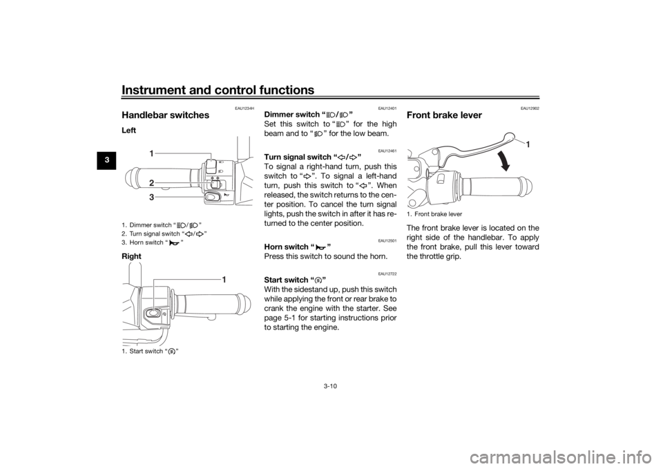
Han dle bar switchesLeft
Ri ght
EAU12401
Dimmer switch “ / ”
Set this switch to “ ” for the high
beam and to “ ” for the low beam.
EAU12461
Turn si gnal switch “ / ”
To signal a right-hand turn, push this
switch to “ ”. To signal a left-hand
turn, push this switch to “ ”. When
released, the switch returns to the cen-
ter position. To cancel the turn signal
lights, push the switch in after it has re-
turned to the center position.
EAU12501
Horn switch “ ”
Press this switch to sound the horn.
EAU12722
Start switch “ ”
With the sidestand up, push this switch
while applying the front or rear brake to
crank the engine with the starter. See
page 5-1 for starting instructions prior
to starting the engine.
EAU12902
Front brake leverThe front brake lever is located on the
right side of the handlebar. To apply
the front brake, pull this lever toward
the throttle grip.
1. Dimmer switch “ / ”
2. Turn signal switch “ / ”
3. Horn switch “ ”
1. Start switch “ ”
123
1
1. Front brake lever
1
U2DSE0E0.book Page 10 Thursday, March 19, 2015 10:34 AM
Page 27 of 90
Instrument and control functions
3-11
3
EAU12952
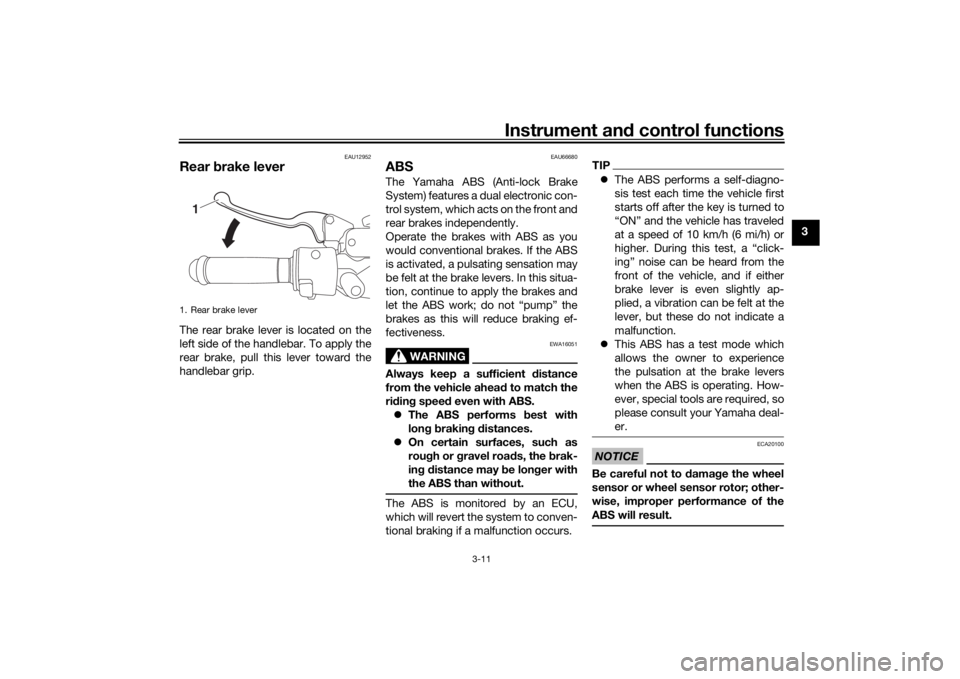
Rear brake leverThe rear brake lever is located on the
left side of the handlebar. To apply the
rear brake, pull this lever toward the
handlebar grip.
EAU66680
ABSThe Yamaha ABS (Anti-lock Brake
System) features a dual electronic con-
trol system, which acts on the front and
rear brakes independently.
Operate the brakes with ABS as you
would conventional brakes. If the ABS
is activated, a pulsating sensation may
be felt at the brake levers. In this situa-
tion, continue to apply the brakes and
let the ABS work; do not “pump” the
brakes as this will reduce braking ef-
fectiveness.
WARNING
EWA16051
Always keep a sufficient d istance
from the vehicle ahea d to match the
ri din g speed even with ABS.
The ABS performs best with
lon g b rakin g d istances.
On certain surfaces, such as
rou gh or g ravel roa ds, the b rak-
in g d istance may be lon ger with
the ABS than without.The ABS is monitored by an ECU,
which will revert the system to conven-
tional braking if a malfunction occurs.
TIP The ABS performs a self-diagno-
sis test each time the vehicle first
starts off after the key is turned to
“ON” and the vehicle has traveled
at a speed of 10 km/h (6 mi/h) or
higher. During this test, a “click-
ing” noise can be heard from the
front of the vehicle, and if either
brake lever is even slightly ap-
plied, a vibration can be felt at the
lever, but these do not indicate a
malfunction.
This ABS has a test mode which
allows the owner to experience
the pulsation at the brake levers
when the ABS is operating. How-
ever, special tools are required, so
please consult your Yamaha deal-
er.NOTICE
ECA20100
Be careful not to d amage the wheel
sensor or wheel sensor rotor; other-
wise, improper performance of the
ABS will result.
1. Rear brake lever
1
U2DSE0E0.book Page 11 Thursday, March 19, 2015 10:34 AM
Page 34 of 90

Instrument and control functions
3-18
3
Turn the key on.
Put the sidestand up.Push the start switch while applying
either of the brake levers. The engine will
start.Put the sidestand down.
If the engine stalls:
The sidestand switch is OK.
• The vehicle must be placed on the center-
stand during this inspection.• If a malfunction is noted, have a Yamaha
dealer check the system before riding.
WARNING
U2DSE0E0.book Page 18 Thursday, March 19, 2015 10:34 AM
Page 35 of 90
For your safety – pre-operation checks
4-1
4
EAU15599
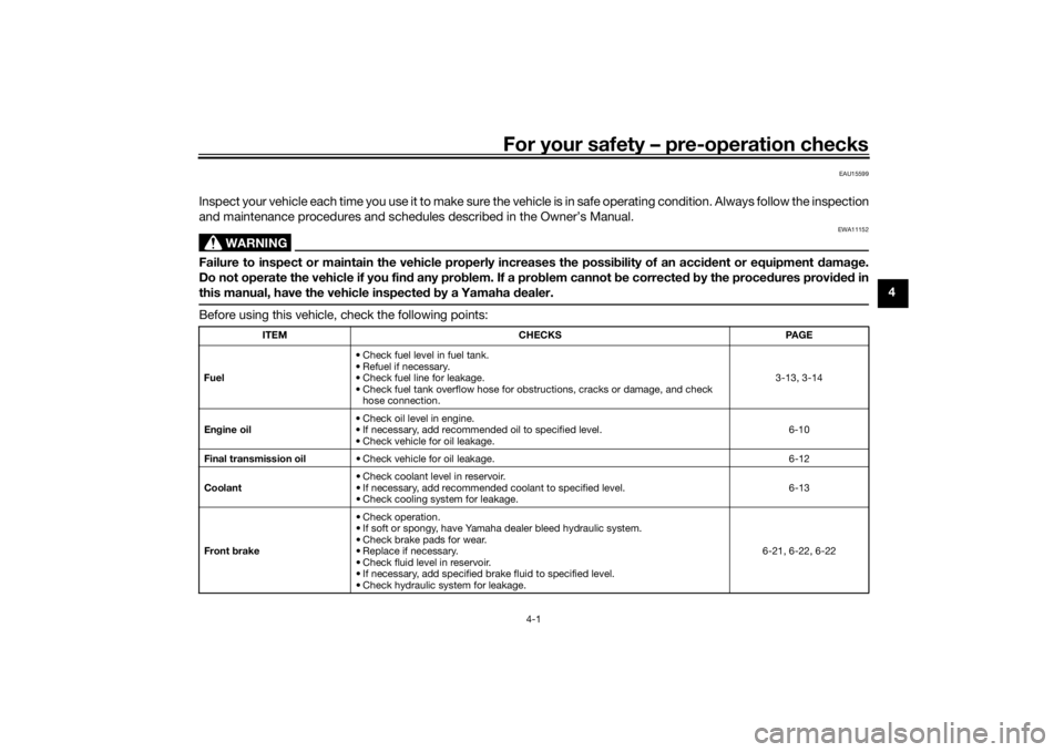
Inspect your vehicle each time you use it to make sure the vehicle is in safe operating condition. Always follow the inspection
and maintenance procedures and schedules described in the Owner’s Manual.
WARNING
EWA11152
Failure to inspect or maintain the vehicle properly increases the possibility of an acci dent or equipment damag e.
Do not operate the vehicle if you fin d any pro blem. If a pro blem cannot be corrected b y the proce dures provi ded in
this manual, have the vehicle inspecte d b y a Yamaha dealer.Before using this vehicle, check the following points:
ITEM CHECKS PAGE
Fuel • Check fuel level in fuel tank.
• Refuel if necessary.
• Check fuel line for leakage.
• Check fuel tank overflow hose for obstructions, cracks or damage, and check
hose connection. 3-13, 3-14
En gine oil • Check oil level in engine.
• If necessary, add recommended oil to specified level.
• Check vehicle for oil leakage. 6-10
Final transmission oil • Check vehicle for oil leakage. 6-12
Coolant • Check coolant level in reservoir.
• If necessary, add recommended coolant to specified level.
• Check cooling system for leakage. 6-13
Front brake • Check operation.
• If soft or spongy, have Yamaha dealer bleed hydraulic system.
• Check brake pads for wear.
• Replace if necessary.
• Check fluid level in reservoir.
• If necessary, add specified brake fluid to specified level.
• Check hydraulic system for leakage. 6-21, 6-22, 6-22
U2DSE0E0.book Page 1 Thursday, March 19, 2015 10:34 AM