engine YAMAHA NMAX 125 2016 Owner's Guide
[x] Cancel search | Manufacturer: YAMAHA, Model Year: 2016, Model line: NMAX 125, Model: YAMAHA NMAX 125 2016Pages: 94, PDF Size: 3.7 MB
Page 81 of 94

Periodic maintenance an d a djustment
6-41
6
En
gine overheatin g
WARNING
EWAT1041
Do not remove the rad iator cap when the engine an d ra diator are hot.
Scal din g hot flui d an d steam may b e blown out un der pressure, which
coul d cause serious injury. Be sure to wait until the en gine has coole d.
Place a thick ra g, like a towel, over the rad iator cap, and then slowly ro-
tate the cap counterclockwise to the d etent to allow any residual pres-
sure to escape. When the hissin g soun d has stoppe d, press d own on the
cap while turnin g it counterclockwise, an d then remove the cap.
TIP
If coolant is not available, tap water can be temporarily used instead, provided
that it is changed to the recommended coolant as soon as possible.
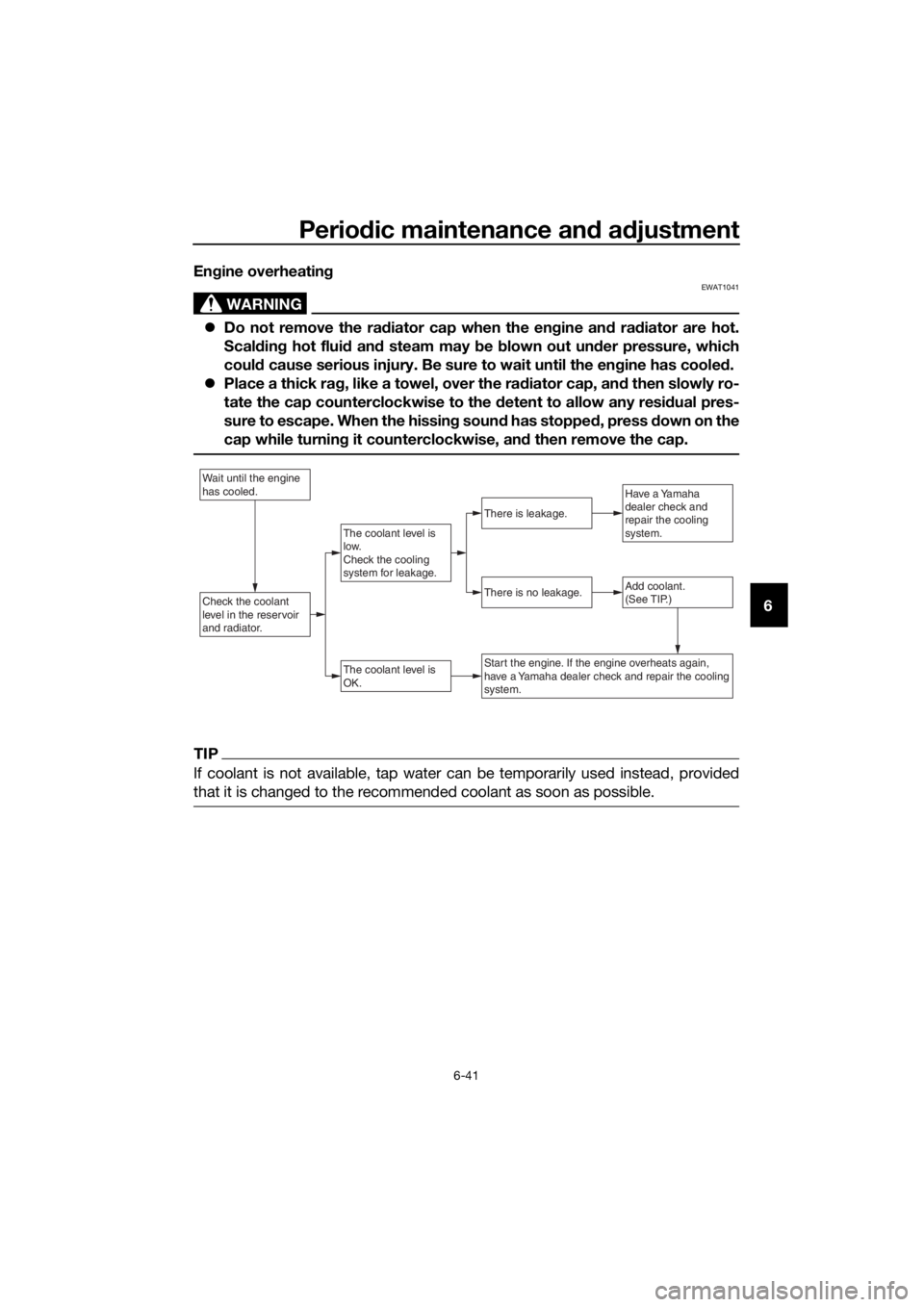
Wait until the engine
has cooled.
Check the coolant
level in the reservoir
and radiator.Add coolant.
(See TIP.)
The coolant level is
OK.
There is no leakage.
There is leakage.
The coolant level is
low.
Check the cooling
system for leakage.
Have a Yamaha
dealer check and
repair the cooling
system.
Start the engine. If the engine overheats again,
have a Yamaha dealer check and repair the cooling
system.
UBV3E0E0.book Page 41 Monday, September 26, 2016 3:42 PM
Page 82 of 94

Scooter care and stora ge
7-1
7
EAU37834
Matte color caution
NOTICE
ECA15193
Some mo dels are equipped with
matte colore d finishe d parts. Be
sure to consult a Yamaha dealer for
a d vice on what pro ducts to use be-
fore cleanin g the vehicle. Usin g a
b rush, harsh chemical prod ucts or
cleanin g compoun ds when cleanin g
these parts will scratch or damag e
their surface. Wax also shoul d not
b e applied to any matte colored fin-
ishe d parts.
EAUN1000
Care
While the open design of a scooter re-
veals the attractiveness of the technol-
ogy, it also makes it more vulnerable.
Rust and corrosion can develop even if
high-quality components are used. A
rusty exhaust pipe may go unnoticed
on a car, however, it detracts from the
overall appearance of a scooter. Fre-
quent and proper care does not only
comply with the terms of the warranty,
but it will also keep your scooter look-
ing good, extend its life and optimize
its performance.
Before cleanin g
1. Cover the muffler outlet with a plastic bag after the engine has
cooled down.
2. Make sure that all caps and cov- ers as well as all electrical cou-
plers and connectors, including
the spark plug cap, are tightly in-
stalled.
3. Remove extremely stubborn dirt, like oil burnt onto the crankcase,
with a degreasing agent and a
brush, but never apply such prod-
ucts onto seals, gaskets and
wheel axles. Always rinse the dirt
and degreaser off with water.
Cleanin g
NOTICE
ECA10784
Avoi d usin g stron g aci dic wheel
cleaners, especially on spoke d
wheels. If such pro ducts are
use d on har d-to-remove dirt, do
not leave the cleaner on the af-
fected area any lon ger than in-
UBV3E0E0.book Page 1 Monday, September 26, 2016 3:42 PM
Page 85 of 94

Scooter care and stora ge
7-4
7
EAU36564
Stora ge
Short-term
Always store your scooter in a cool, dry
place and, if necessary, protect it
against dust with a porous cover. Be
sure the engine and the exhaust sys-
tem are cool before covering the
scooter.
NOTICE
ECA10821
Storin g the scooter in a poorly
ventilate d room or coverin g it
with a tarp, while it is still wet,
will allow water an d humi dity to
seep in an d cause rust.
To prevent corrosion, avoi d
d amp cellars, sta bles ( because
of the presence of ammonia)
an d areas where stron g chemi-
cals are store d.
Lon g-term
Before storing your scooter for several
months: 1. Follow all the instructions in the “Care” section of this chapter.
2. Fill up the fuel tank and add fuel stabilizer (if available) to prevent
the fuel tank from rusting and the
fuel from deteriorating.
3. Perform the following steps to protect the cylinder, piston rings,
etc. from corrosion.a. Remove the spark plug cap and spark plug.
b. Pour a teaspoonful of engine oil into the spark plug bore.
c. Install the spark plug cap onto the spark plug, and then place
the spark plug on the cylinder head so that the electrodes are
grounded. (This will limit spark-
ing during the next step.)
d. Turn the engine over several times with the starter. (This will
coat the cylinder wall with oil.)
e. Remove the spark plug cap from the spark plug, and then
install the spark plug and the
spark plug cap. WARNING! To
prevent damag e or injury
from sparkin g, make sure to
g roun d the spark plu g elec-
tro des while turnin g the en-
g ine over.
[EWA10952]
4. Lubricate all control cables and
the pivoting points of all levers and
pedals as well as of the side-
stand/centerstand.
5. Check and, if necessary, correct the tire air pressure, and then lift
the scooter so that both of its
wheels are off the ground. Alterna-
tively, turn the wheels a little every
month in order to prevent the tires
from becoming degraded in one
spot.
6. Cover the muffler outlet with a plastic bag to prevent moisture
from entering it.
7. Remove the battery and fully charge it. Store it in a cool, dry
place and charge it once a month.
Do not store the battery in an ex-
cessively cold or warm place [less
than 0 °C (30 °F) or more than 30
°C (90 °F)]. For more information
on storing the battery, see page
6-30.
UBV3E0E0.book Page 4 Monday, September 26, 2016 3:42 PM
Page 87 of 94

Specifications
8-1
8
Dimensions:
Overall length:1955 mm (77.0 in)
Overall width:
740 mm (29.1 in)
Overall height: 1115 mm (43.9 in)
Seat height: 765 mm (30.1 in)
Wheelbase:
1350 mm (53.1 in)
Ground clearance: 135 mm (5.31 in)
Minimum turning radius: 2.0 m (6.56 ft)
Wei ght:
Curb weight:
127 kg (280 lb)
Engine:
Combustion cycle:
4-stroke
Cooling system:
Liquid cooled
Valve train: SOHC
Number of cylinders: Single cylinder
Displacement:
125 cm³ (GPD125-A)
155 cm³ (GPD150-A)
Bore × stroke:
52.0 × 5 8 . 7 m m (2 . 0 5 × 2.31 in) (GPD125-A)
58.0 × 5 8 . 7 m m (2 . 2 8 × 2.31 in) (GPD150-A)
Compression ratio:
10.5 : 1 (GPD150-A)
11.2 : 1 (GPD125-A)
Starting system:
Electric starter
Lubrication system: Wet sump
Engine oil:
Recommended brand:
YAMALUBE
SAE viscosity grades: 10W-40
Recommended engine oil grade: API service SG type or higher, JASO
standard MA or MB Engine oil quantity:
Oil change:
0.90 L (0.95 US qt, 0.79 Imp.qt)
Final transmission oil:
Type: Motor oil SAE 10W-30 type SE or higher or
Gear oil SAE 85W GL-3
Quantity: 0.15 L (0.16 US qt, 0.13 Imp.qt)
Coolant quantity:
Coolant reservoir (up to the maximum level
mark):
0.25 L (0.26 US qt, 0.22 Imp.qt)
Radiator (including all routes):
0.46 L (0.49 US qt, 0.40 Imp.qt)
Air filter:
Air filter element:Oil-coated paper element
Fuel:
Recommended fuel:Regular unleaded gasoline (Gasohol [E10]
acceptable)
Fuel tank capacity: 6.6 L (1.7 US gal, 1.5 Imp.gal)
Fuel reserve amount: 1.4 L (0.37 US gal, 0.31 Imp.gal)
Fuel injection:
Throttle body:ID mark:
2DS1 00
Spark plu g(s):
Manufacturer/model:
NGK/CPR8EA-9
Spark plug gap:
0.8–0.9 mm (0.031–0.035 in)
Clutch:
Clutch type:Dry, centrifugal, shoe
Drivetrain:
Primary reduction ratio:1.000
Final drive: Gear
Secondary reduction ratio:
10.208 (56/16 x 35/12)
Transmission type: V-belt automatic
Chassis:
Frame type:
Underbone
UBV3E0E0.book Page 1 Monday, September 26, 2016 3:42 PM
Page 89 of 94

Specifications
8-3
8
Turn signal indicator light:LED
Coolant temperature warning light: LED
Engine trouble warning light:
LED
ABS warning light: LED
Fuse(s):
Main fuse:
15.0 A
Main fuse 2: 7.5 A
Taillight fuse: 7.5 A
Signaling system fuse: 7.5 A
ABS control unit fuse:
7.5 A
ABS motor fuse: 30.0 A
ABS solenoid fuse: 15.0 A
UBV3E0E0.book Page 3 Monday, September 26, 2016 3:42 PM
Page 90 of 94

Consumer information
9-1
9
EAU53562
Id entification num bers
Record the vehicle identification num-
ber, engine serial number, and the
model label information in the spaces
provided below. These identification
numbers are needed when registering
the vehicle with the authorities in your
area and when ordering spare parts
from a Yamaha dealer.
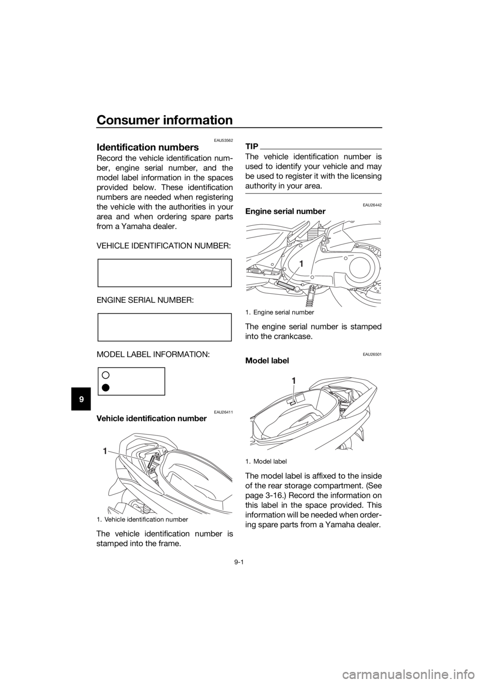
VEHICLE IDENTIFICATION NUMBER:
ENGINE SERIAL NUMBER:
MODEL LABEL INFORMATION:
EAU26411Vehicle i dentification num ber
The vehicle identification number is
stamped into the frame.
TIP
The vehicle identification number is
used to identify your vehicle and may
be used to register it with the licensing
authority in your area.
EAU26442En gine serial num ber
The engine serial number is stamped
into the crankcase.
EAU26501Mo del lab el
The model label is affixed to the inside
of the rear storage compartment. (See
page 3-16.) Record the information on
this label in the space provided. This
information will be needed when order-
ing spare parts from a Yamaha dealer.
1. Vehicle identification number
1
1. Engine serial number
1. Model label
1
1
UBV3E0E0.book Page 1 Monday, September 26, 2016 3:42 PM
Page 91 of 94

Consumer information
9-2
9
EAU69910
Diagnostic connector
The diagnostic connector is located as
shown.
EAU74701
Vehicle data recor din g
This model’s ECU stores certain vehi-
cle data to assist in the diagnosis of
malfunctions and for research and de-
velopment purposes. This data will be
uploaded only when a special Yamaha
diagnostic tool is attached to the vehi-
cle, such as when maintenance checks
or service procedures are performed.
Although the sensors and recorded
data will vary by model, the main data
points are:
Vehicle status and engine perfor-
mance data
Fuel-injection and emission-relat-
ed data
Yamaha will not disclose this data to a third party except: With the consent of the vehicle
owner
Where obligated by law
For use by Yamaha in litigation
For general Yamaha-conducted
research purposes when the data
is not related to an individual vehi-
cle nor owner
1. FI diagnostic connector
1
UBV3E0E0.book Page 2 Monday, September 26, 2016 3:42 PM
Page 92 of 94

10-1
10
Index
A
ABS ....................................................... 3-11
ABS warning light ................................... 3-3
Acceleration and deceleration ................ 5-3
Air filter and V-belt case air filter
elements ............................................. 6-17
Auxiliary light bulb, replacing ................ 6-34
B
Battery .................................................. 6-30
Brake fluid, changing ............................ 6-26
Brake fluid level, checking .................... 6-25
Brake lever, front .................................. 3-10
Brake lever, rear.................................... 3-11
Brake levers, lubricating ....................... 6-28
Brake light ............................................. 6-35
Braking.................................................... 5-3
C
Cables, checking and lubricating ......... 6-27
Care ........................................................ 7-1
Catalytic converter ................................ 3-15
Centerstand and sidestand, checking and lubricating .................... 6-28
Coolant ................................................. 6-13
Coolant temperature warning light ......... 3-3
D
Data recording, vehicle ........................... 9-2
Diagnostic connector.............................. 9-2
Dimmer switch ........................................ 3-9
E
Engine break-in....................................... 5-4
Engine oil and oil strainer...................... 6-10
Engine serial number .............................. 9-1
Engine trouble warning light ................... 3-3
F
Final transmission oil ............................ 6-12
Front and rear brake lever free play, checking ............................................. 6-23
Front and rear brake pads, checking.... 6-24
Front fork, checking .............................. 6-29
Fuel ....................................................... 3-13
Fuel consumption, tips for reducing ....... 5-4
Fuel tank cap ........................................ 3-12
Fuel tank overflow hose ........................ 3-15
Fuses, replacing.................................... 6-32
H
Handlebar switches ................................ 3-9
Headlight............................................... 6-33
High beam indicator light........................ 3-3
Horn switch ........................................... 3-10
I
Identification numbers ............................ 9-1
Ignition circuit cut-off system............... 3-18
Indicator lights and warning lights ......... 3-3
K
Keyhole shutter ...................................... 3-2
M
Main switch/steering lock....................... 3-1
Maintenance and lubrication, periodic ... 6-4
Maintenance, emission control system.................................................. 6-3
Matte color, caution ............................... 7-1
Model label ............................................. 9-1
Multi-function meter unit ........................ 3-4
P
Panels, removing and installing.............. 6-7
Parking ................................................... 5-5
Part locations ......................................... 2-1
S
Safe-riding points ................................... 1-5
Safety information .................................. 1-1
Seat ...................................................... 3-16
Sidestand ............................................. 3-17
Spark plug, checking ............................. 6-9
Specifications ......................................... 8-1
Starting off.............................................. 5-2
Starting the engine ................................. 5-1
Start switch .......................................... 3-10
Steering, checking................................ 6-29
Storage ................................................... 7-4
Storage compartments ........................ 3-16
T
Taillight bulb, replacing ........................ 6-35
Throttle grip and cable, checking and lubricating .................... 6-27
Throttle grip free play, checking........... 6-19
Tires ...................................................... 6-20
Tool kit.................................................... 6-2
Troubleshooting ................................... 6-39
Troubleshooting charts ........................ 6-40
Turn signal indicator lights ..................... 3-3
Turn signal light bulb (front), replacing ............................................ 6-37
Turn signal light bulb (rear), replacing ............................................ 6-38
Turn signal switch .................................. 3-9
V
Valve clearance .................................... 6-20
V-belt, checking ................................... 6-26
Vehicle identification number ................. 9-1
UBV3E0E0.book Page 1 Monday, September 26, 2016 3:42 PM