YAMAHA NMAX 125 2021 Owners Manual
Manufacturer: YAMAHA, Model Year: 2021, Model line: NMAX 125, Model: YAMAHA NMAX 125 2021Pages: 114, PDF Size: 10.63 MB
Page 111 of 114

Consumer information
12-3
12 Yamaha will not disclose this data to a
third party except in the following cas-
es. In addition, Yamaha may provide
vehicle data to a contractor in order to
outsource services related to the han-
dling of vehicle data. Even in this case,
Yamaha will require the contractor to
properly handle the vehicle data we
provided and Yamaha will appropriate-
ly manage the data.
With the consent of the vehicle
owner
Where obligated by law
For use by Yamaha in litigation
When the data is not related to an
individual vehicle nor owner
UBALE0E0.book Page 3 Wednesday, September 30, 2020 1:37 PM
Page 112 of 114

13-1
13
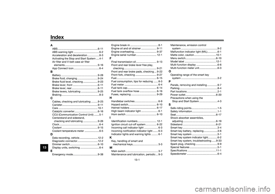
IndexAABS ....................................................... 6-11
ABS warning light ................................... 6-2
Acceleration and deceleration ................ 8-3
Activating the Stop and Start System .... 4-1
Air filter and V-belt case air filter
elements ............................................. 9-16
App Connect icon ................................... 6-4BBattery .................................................. 9-28
Brake fluid, changing ............................ 9-24
Brake fluid level, checking .................... 9-23
Brake lever, front .................................. 6-11
Brake lever, rear.................................... 6-11
Brake levers, lubricating ....................... 9-25
Braking.................................................... 8-3CCables, checking and lubricating ......... 9-25
Canister................................................. 9-11
Care ...................................................... 10-1
Catalytic converter ................................ 6-16
CCU (Communication Control Unit) ....... 5-1
Centerstand and sidestand,
checking and lubricating .................... 9-26
Clock....................................................... 6-4
Coolant ................................................. 9-15
Coolant temperature meter .................... 6-5DData recording, vehicle ......................... 12-2
Diagnostic connector............................ 12-2
Dimmer switch ...................................... 6-10
Display units, switching .......................... 6-4EEmergency mode.................................. 9-38Engine break-in ...................................... 8-1
Engine oil and oil strainer ..................... 9-11
Engine overheating ............................... 9-37
Engine serial number ............................ 12-1
FFinal transmission oil ............................ 9-13
Front and rear brake lever free play,
checking............................................. 9-21
Front and rear brake pads, checking ... 9-22
Front fork, checking ............................. 9-27
Fuel ....................................................... 6-15
Fuel consumption, tips for reducing ...... 8-3
Fuel meter .............................................. 6-4
Fuel tank cap ........................................ 6-14
Fuel tank overflow hose ....................... 6-16
Fuses, replacing ................................... 9-29HHandlebar switches ................................ 6-9
Hazard switch....................................... 6-10
Helmet holders ..................................... 6-17
High beam indicator light ....................... 6-1
Horn switch .......................................... 6-10IIdentification numbers .......................... 12-1
Ignition circuit cut-off system ............... 6-22
Incoming call indicator light ................... 6-3
Incoming notification indicator light ....... 6-3
Indicator lights and warning lights ......... 6-1KKey, handling of smart and
mechanical keys................................... 3-3MMain switch ............................................ 3-7
Maintenance and lubrication, periodic ... 9-3Maintenance, emission control
system ..................................................9-2
Malfunction indicator light (MIL)..............6-1
Matte color, caution ..............................10-1
Menu switch..........................................6-10
Model label ...........................................12-1
Multi-function display .............................6-6
Multi-function meter unit .........................6-3
OOperating range of the smart key
system ..................................................3-2PPanels, removing and installing ..............9-7
Parking ....................................................8-4
Part locations ..........................................2-1
Power outlet ..........................................6-20
Precautions when using the
Stop and Start System .........................4-3SSafe-riding points....................................1-5
Safety information ...................................1-1
Seat .......................................................6-17
Shock absorber assemblies,
adjusting .............................................6-19
Sidestand ..............................................6-21
Smart key ................................................3-4
Smart key battery, replacing ...................3-6
Smart key system ...................................3-1
Smart key system indicator light.............6-2
Smart key system, troubleshooting ......9-33
Spark plug, checking ..............................9-9
Special features ......................................5-1
Specifications .......................................11-1
Speedometer ..........................................6-4
UBALE0E0.book Page 1 Wednesday, September 30, 2020 1:37 PM
Page 113 of 114

Index
13-2
13
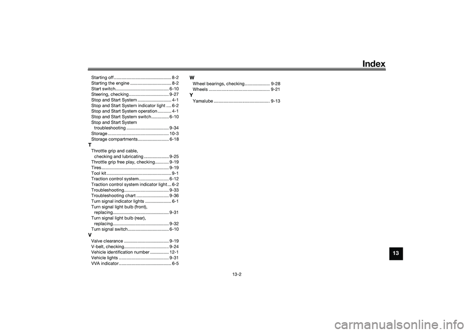
Starting off .............................................. 8-2
Starting the engine ................................. 8-2
Start switch........................................... 6-10
Steering, checking ................................ 9-27
Stop and Start System ........................... 4-1
Stop and Start System indicator light .... 6-2
Stop and Start System operation ........... 4-1
Stop and Start System switch .............. 6-10
Stop and Start System
troubleshooting .................................. 9-34
Storage ................................................. 10-3
Storage compartments......................... 6-18TThrottle grip and cable,
checking and lubricating .................... 9-25
Throttle grip free play, checking ........... 9-19
Tires ...................................................... 9-19
Tool kit .................................................... 9-1
Traction control system ........................ 6-12
Traction control system indicator light ... 6-2
Troubleshooting.................................... 9-33
Troubleshooting chart .......................... 9-36
Turn signal indicator lights ..................... 6-1
Turn signal light bulb (front),
replacing............................................. 9-31
Turn signal light bulb (rear),
replacing............................................. 9-32
Turn signal switch................................. 6-10VValve clearance .................................... 9-19
V-belt, checking.................................... 9-24
Vehicle identification number ............... 12-1
Vehicle lights ........................................ 9-31
VVA indicator .......................................... 6-5
WWheel bearings, checking .................... 9-28
Wheels ................................................. 9-21YYamalube ............................................. 9-13
UBALE0E0.book Page 2 Wednesday, September 30, 2020 1:37 PM
Page 114 of 114

DIC183
PRINTED IN INDONESIA2020.12
Original instructions