key YAMAHA NMAX 125 2021 Owner's Manual
[x] Cancel search | Manufacturer: YAMAHA, Model Year: 2021, Model line: NMAX 125, Model: YAMAHA NMAX 125 2021Pages: 114, PDF Size: 10.63 MB
Page 96 of 114
Periodic maintenance and adjustment
9-33
910. Close the seat.
EAU60701
TroubleshootingAlthough Yamaha vehicles receive a
thorough inspection before shipment
from the factory, trouble may occur
during operation. Any problem in the
fuel, compression, or ignition systems,
for example, can cause poor starting
and loss of power.
The following troubleshooting charts
represent quick and easy procedures
for checking these vital systems your-
self. However, should your vehicle re-
quire any repair, take it to a Yamaha
dealer, whose skilled technicians have
the necessary tools, experience, and
know-how to service the vehicle prop-
erly.
Use only genuine Yamaha replace-
ment parts. Imitation parts may look
like Yamaha parts, but they are often
inferior, have a shorter service life and
can lead to expensive repair bills.
WARNING
EWA15142
When checking the fuel system, do
not smoke, and make sure there are
no open flames or sparks in the ar-
ea, including pilot lights from waterheaters or furnaces. Gasoline or
gasoline vapors can ignite or ex-
plode, causing severe injury or prop-
erty damage.
EAU76551
Smart key system troubleshooting
Please check the following items when
the smart key system does not work.
Is the smart key turned on? (See
page 3-4.)
Is the smart key battery dis-
charged? (See page 3-6.)
Is the smart key battery installed
correctly? (See page 3-6.)
Is the smart key being used in a lo-
cation with strong radio waves or
other electromagnetic noise? (See
page 3-1.)
Are you using the smart key that is
registered to the vehicle?
Is the vehicle battery discharged?
When the vehicle battery is dis-
charged, the smart key system will
not operate. Please have the vehi-
cle battery charged or replaced.
(See page 9-28.)
Tightening torque:
Grab bar bolt:
17 N·m (1.7 kgf·m, 13 lb·ft)
UBALE0E0.book Page 33 Wednesday, September 30, 2020 1:37 PM
Page 97 of 114
Periodic maintenance and adjustment
9-34
9 If the smart key system does not work
after checking the above items, have a
Yamaha dealer check the smart key
system.
TIPSee Emergency mode on page 9-38
for information on starting the engine
without the smart key.
EAU76843
Stop and Start System trouble-
shooting
If a problem occurs, check the follow-
ing before taking the vehicle to a
Yamaha dealer.
The Stop and Start System indicator
light does not come on.
1. Is the main switch turned on?
2. Is the Stop and Start System
switch set to “ ”?
3. Was the engine warmed up suffi-
ciently after starting?
4. After the engine was warmed up,
was the engine left idling for a cer-
tain period of time?
5. Did the vehicle travel at a speed of
10 km/h or higher?Even if the preceding conditions are
met, the Stop and Start System may
not activate in order to preserve bat-
tery power. In this case, continue to
drive the vehicle.
In addition, the Stop and Start System
indicator light does not come on if the
engine trouble warning light is on.
If the Stop and Start System indicator
light still does not come on after you
checked the preceding conditions,
have a Yamaha dealer check the vehi-
cle as soon as possible.
The Stop and Start System indicator
light comes on, but the engine does
not stop automatically.
1. Was the vehicle stopped com-
pletely?
The engine may not stop automat-
ically until the vehicle is stopped
for a certain period of time. Try
bringing the vehicle to a complete
stop.
2. Is the throttle grip turned?
The engine does not stop auto-
matically if the throttle grip is not in
the fully closed position.Turn the throttle grip to the fully
closed position.
If the engine still does not stop auto-
matically after you checked the pre-
ceding conditions, have a Yamaha
dealer check the vehicle as soon as
possible.
After the engine was stopped by the
Stop and Start System, the engine
does not restart even if the throttle
grip is turned.
1. Is the Stop and Start System
switch set to “ ”?
If the Stop and Start System
switch is set to “ ” while the Stop
and Start System is activated, the
Stop and Start System will be
turned off.
2. Was the sidestand operated?
When the sidestand is lowered,
the Stop and Start System is de-
activated.
3. Was the engine left stopped by
the Stop and Start System for a
long period of time?
A
AA
UBALE0E0.book Page 34 Wednesday, September 30, 2020 1:37 PM
Page 101 of 114
Periodic maintenance and adjustment
9-38
9
EAU76561
Emergency mode When the smart key is lost or dam-
aged, or its battery has discharged, the
vehicle can still be turned on and the
engine started. You will need the smart
key system identification number.
To operate the vehicle in emergency
mode
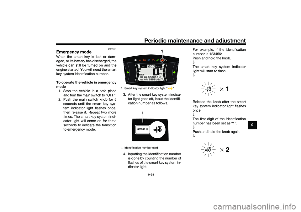
1. Stop the vehicle in a safe place
and turn the main switch to “OFF”.
2. Push the main switch knob for 5
seconds until the smart key sys-
tem indicator light flashes once,
then release it. Repeat two more
times. The smart key system indi-
cator light will come on for three
seconds to indicate the transition
to emergency mode.3. After the smart key system indica-
tor light goes off, input the identifi-
cation number as follows.
4. Inputting the identification number
is done by counting the number of
flashes of the smart key system in-
dicator light.For example, if the identification
number is 123456:
Push and hold the knob.
↓
The smart key system indicator
light will start to flash.
↓
Release the knob after the smart
key system indicator light flashes
once.
↓
The first digit of the identification
number has been set as “1”.
↓
Push and hold the knob again.
↓
1. Smart key system indicator light “ ”
1. Identification number card
1
868588
1
UBALE0E0.book Page 38 Wednesday, September 30, 2020 1:37 PM
Page 102 of 114
Periodic maintenance and adjustment
9-39
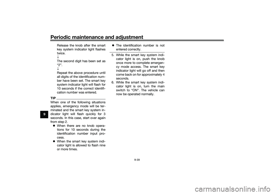
9Release the knob after the smart
key system indicator light flashes
twice.
↓
The second digit has been set as
“2”.
↓
Repeat the above procedure until
all digits of the identification num-
ber have been set. The smart key
system indicator light will flash for
10 seconds if the correct identifi-
cation number was entered.
TIPWhen one of the following situations
applies, emergency mode will be ter-
minated and the smart key system in-
dicator light will flash quickly for 3
seconds. In this case, start over again
from step 2.
When there are no knob opera-
tions for 10 seconds during the
identification number input pro-
cess.
When the smart key system indi-
cator light is allowed to flash nine
or more times.The identification number is not
entered correctly.
5. While the smart key system indi-
cator light is on, push the knob
once more to complete emergen-
cy mode access. The smart key
indicator light will go off and then
come back on for approximately 4
seconds.
6. While the smart key system indi-
cator light is on, turn the main
switch to “ON”. The vehicle can
now be operated normally.
UBALE0E0.book Page 39 Wednesday, September 30, 2020 1:37 PM
Page 112 of 114
13-1
13
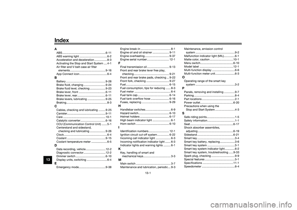
IndexAABS ....................................................... 6-11
ABS warning light ................................... 6-2
Acceleration and deceleration ................ 8-3
Activating the Stop and Start System .... 4-1
Air filter and V-belt case air filter
elements ............................................. 9-16
App Connect icon ................................... 6-4BBattery .................................................. 9-28
Brake fluid, changing ............................ 9-24
Brake fluid level, checking .................... 9-23
Brake lever, front .................................. 6-11
Brake lever, rear.................................... 6-11
Brake levers, lubricating ....................... 9-25
Braking.................................................... 8-3CCables, checking and lubricating ......... 9-25
Canister................................................. 9-11
Care ...................................................... 10-1
Catalytic converter ................................ 6-16
CCU (Communication Control Unit) ....... 5-1
Centerstand and sidestand,
checking and lubricating .................... 9-26
Clock....................................................... 6-4
Coolant ................................................. 9-15
Coolant temperature meter .................... 6-5DData recording, vehicle ......................... 12-2
Diagnostic connector............................ 12-2
Dimmer switch ...................................... 6-10
Display units, switching .......................... 6-4EEmergency mode.................................. 9-38Engine break-in ...................................... 8-1
Engine oil and oil strainer ..................... 9-11
Engine overheating ............................... 9-37
Engine serial number ............................ 12-1
FFinal transmission oil ............................ 9-13
Front and rear brake lever free play,
checking............................................. 9-21
Front and rear brake pads, checking ... 9-22
Front fork, checking ............................. 9-27
Fuel ....................................................... 6-15
Fuel consumption, tips for reducing ...... 8-3
Fuel meter .............................................. 6-4
Fuel tank cap ........................................ 6-14
Fuel tank overflow hose ....................... 6-16
Fuses, replacing ................................... 9-29HHandlebar switches ................................ 6-9
Hazard switch....................................... 6-10
Helmet holders ..................................... 6-17
High beam indicator light ....................... 6-1
Horn switch .......................................... 6-10IIdentification numbers .......................... 12-1
Ignition circuit cut-off system ............... 6-22
Incoming call indicator light ................... 6-3
Incoming notification indicator light ....... 6-3
Indicator lights and warning lights ......... 6-1KKey, handling of smart and
mechanical keys................................... 3-3MMain switch ............................................ 3-7
Maintenance and lubrication, periodic ... 9-3Maintenance, emission control
system ..................................................9-2
Malfunction indicator light (MIL)..............6-1
Matte color, caution ..............................10-1
Menu switch..........................................6-10
Model label ...........................................12-1
Multi-function display .............................6-6
Multi-function meter unit .........................6-3
OOperating range of the smart key
system ..................................................3-2PPanels, removing and installing ..............9-7
Parking ....................................................8-4
Part locations ..........................................2-1
Power outlet ..........................................6-20
Precautions when using the
Stop and Start System .........................4-3SSafe-riding points....................................1-5
Safety information ...................................1-1
Seat .......................................................6-17
Shock absorber assemblies,
adjusting .............................................6-19
Sidestand ..............................................6-21
Smart key ................................................3-4
Smart key battery, replacing ...................3-6
Smart key system ...................................3-1
Smart key system indicator light.............6-2
Smart key system, troubleshooting ......9-33
Spark plug, checking ..............................9-9
Special features ......................................5-1
Specifications .......................................11-1
Speedometer ..........................................6-4
UBALE0E0.book Page 1 Wednesday, September 30, 2020 1:37 PM