engine YAMAHA PW50 2014 User Guide
[x] Cancel search | Manufacturer: YAMAHA, Model Year: 2014, Model line: PW50, Model: YAMAHA PW50 2014Pages: 76, PDF Size: 1.74 MB
Page 33 of 76
INSTRUMENT AND CONTROL FUNCTIONS
4-6
4
EAU13454
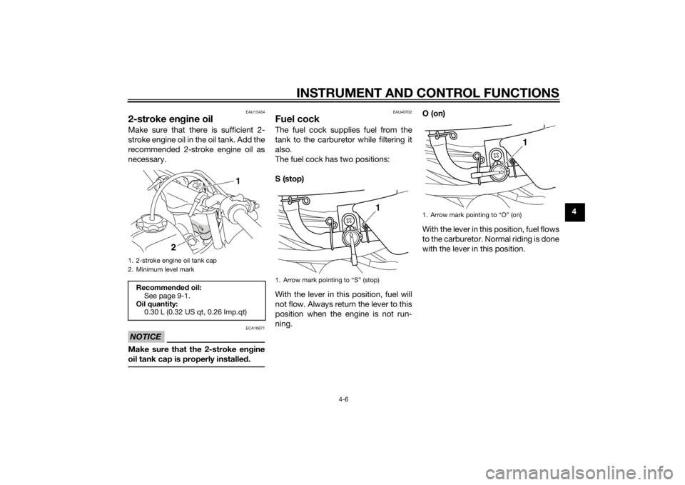
2-stroke engine oilMake sure that there is sufficient 2-
stroke engine oil in the oil tank. Add the
recommended 2-stroke engine oil as
necessary.NOTICE
ECA16671
Make sure that the 2-stroke en gine
oil tank cap is properly installe d.
EAU40702
Fuel cockThe fuel cock supplies fuel from the
tank to the carburetor while filtering it
also.
The fuel cock has two positions:
S (stop)
With the lever in this position, fuel will
not flow. Always return the lever to this
position when the engine is not run-
ning. O (on)
With the lever in this position, fuel flows
to the carburetor. Normal riding is done
with the lever in this position.
1. 2-stroke engine oil tank cap
2. Minimum level markRecommen
ded oil:
See page 9-1.
Oil quantity: 0.30 L (0.32 US qt, 0.26 Imp.qt)
2 1
1. Arrow mark pointing to “S” (stop)
1
1. Arrow mark pointing to “O” (on)
1
U2SA80E0.book Page 6 Monday, June 3, 2013 5:25 PM
Page 34 of 76
INSTRUMENT AND CONTROL FUNCTIONS
4-7
4
EAU13591
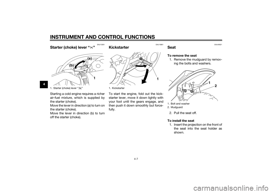
Starter (choke) lever “ ”Starting a cold engine requires a richer
air-fuel mixture, which is supplied by
the starter (choke).
Move the lever in direction (a) to turn on
the starter (choke).
Move the lever in direction (b) to turn
off the starter (choke).
EAU13681
KickstarterTo start the engine, fold out the kick-
starter lever, move it down lightly with
your foot until the gears engage, and
then push it down smoothly but force-
fully.
EAU40921
SeatTo remove the seat1. Remove the mudguard by remov- ing the bolts and washers.
2. Pull the seat off.
To install the seat 1. Insert the projection on the front of the seat into the seat holder as
shown.
1. Starter (choke) lever “ ”
1
(a)
(b)
1. Kickstarter
1
1. Bolt and washer
2. Mudguard
1 2
U2SA80E0.book Page 7 Monday, June 3, 2013 5:25 PM
Page 38 of 76
OPERATION AND IMPORTANT RIDING POINTS
6-1
6
EAU15952
Read the Owner’s Manual carefully to
become familiar with all controls. If
there is a control or function you do not
understand, ask your Yamaha dealer.
WARNING
EWA10272
Failure to familiarize yourself with
the controls can lead to loss of con-
trol, which coul d cause an acci dent
or injury.
EAU4088A
Startin g an d warmin g up a
col d en gine1. Turn the fuel cock lever to “O”
(on).
2. Set the engine stop switch to “START”.
3. Turn the starter (choke) on and completely close the throttle. (See
page 4-7.)
4. While applying the front or rear brake, start the engine by pushing
the kickstarter lever down.
5. After starting the engine, move the starter (choke) back halfway.
6. When the engine is warm, turn the starter (choke) off and set the en-
gine stop switch to “RUN”.TIPThe engine is warm when it responds
quickly to the throttle with the starter
(choke) turned off.NOTICE
ECA11043
For maximum en gine life, never ac-
celerate har d when the en gine is
col d!
EAU16661
Startin g a warm en gineFollow the same procedure as for
starting a cold engine with the excep-
tion that the starter (choke) is not re-
quired when the engine is warm.
Instead, start the engine with the throt-
tle slightly open.TIPIf the engine does not start after sever-
al kicks, try again with the throttle 1/4
to 1/2 open.
U2SA80E0.book Page 1 Monday, June 3, 2013 5:25 PM
Page 39 of 76
OPERATION AND IMPORTANT RIDING POINTS
6-2
6
EAU41003
Starting off1. While applying the rear brake le-
ver, push the motorcycle off the
centerstand.
2. Completely close the throttle.
3. Set the engine stop switch to “RUN”.
4. Check for oncoming off-road vehi- cles, and then slowly turn the
throttle grip in order to take off.
EAU16781
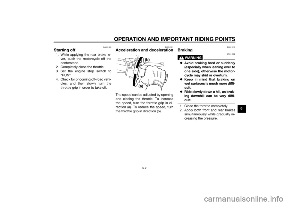
Acceleration an d d ecelerationThe speed can be adjusted by opening
and closing the throttle. To increase
the speed, turn the throttle grip in di-
rection (a). To reduce the speed, turn
the throttle grip in direction (b).
EAU41013
Brakin g
WARNING
EWA14572
Avoi d b rakin g har d or su ddenly
(especially when leanin g over to
one si de), otherwise the motor-
cycle may ski d or overturn.
Keep in min d that brakin g on
wet surfaces is much more diffi-
cult.
Ride slowly d own a hill, as brak-
in g d ownhill can be very diffi-
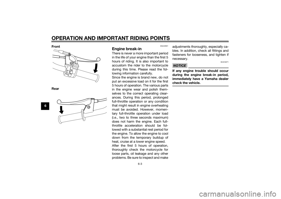
cult.1. Close the throttle completely.
2. Apply both front and rear brakes simultaneously while gradually in-
creasing the pressure.
(a) (b)
U2SA80E0.book Page 2 Monday, June 3, 2013 5:25 PM
Page 40 of 76
OPERATION AND IMPORTANT RIDING POINTS
6-3
6Front
Rear
EAU42031
En
gine break-inThere is never a more important period
in the life of your engine than the first 5
hours of riding. It is also important to
accustom the rider to the motorcycle
during this time. Please read the fol-
lowing information carefully.
Since the engine is brand new, do not
put an excessive load on it for the first
5 hours of operation. The various parts
in the engine wear and polish them-
selves to the correct operating clear-
ances. During this period, prolonged
full-throttle operation or any condition
that might result in engine overheating
must be avoided. However, momen-
tary full-throttle operation under load
(i.e., two to three seconds maximum)
does not harm the engine. Each full-
throttle acceleration should be fol-
lowed with a substantial rest period for
the engine. To allow the engine to cool
down from the temporary buildup of
heat, cruise at a lower engine speed.
After the first 5 hours of operation,
thoroughly check the motorcycle for
loose parts, oil leakage and any other
problems. Be sure to inspect and make adjustments thoroughly, especially ca-
bles. In addition, check all fittings and
fasteners for looseness, and tighten if
necessary.
NOTICE
ECA10271
If any en
gine trou ble shoul d occur
d urin g the en gine break-in perio d,
imme diately have a Yamaha dealer
check the vehicle.
U2SA80E0.book Page 3 Monday, June 3, 2013 5:25 PM
Page 41 of 76

OPERATION AND IMPORTANT RIDING POINTS
6-4
6
EAU40723
ParkingWhen parking, stop the engine, and
then turn the fuel cock lever to “S”
(stop).
WARNING
EWA10312
Since the en gine an d exhaust
system can b ecome very hot,
park in a place where pe destri-
ans or chil dren are not likely to
touch them an d b e burne d.
Do not park on a slope or on soft
groun d, otherwise the vehicle
may overturn, increasin g the
risk of a fuel leak an d fire.
Do not park near grass or other
flamma ble materials which
mi ght catch fire.
U2SA80E0.book Page 4 Monday, June 3, 2013 5:25 PM
Page 42 of 76
PERIODIC MAINTENANCE AND ADJUSTMENT
7-1
7
EAU17245
Periodic inspection, adjustment, and
lubrication will keep your vehicle in the
safest and most efficient condition
possible. Safety is an obligation of the
vehicle owner/operator. The most im-
portant points of vehicle inspection,
adjustment, and lubrication are ex-
plained on the following pages.
The intervals given in the periodic
maintenance charts should be simply
considered as a general guide under
normal riding conditions. However, de-
pending on the weather, terrain, geo-
graphical location, and individual use,
the maintenance intervals may need to
be shortened.
WARNING
EWA10322
Failure to properly maintain the vehi-
cle or performing maintenance ac-
tivities incorrectly may increase
your risk of injury or death durin g
service or while usin g the vehicle. If
you are not familiar with vehicle ser-
vice, have a Yamaha d ealer perform
service.
WARNING
EWA15123
Turn off the en gine when performin g
maintenance unless otherwise
specified .
A runnin g en gine has movin g
parts that can catch on body
parts or clothin g an d electrical
parts that can cause shocks or
fires.
Runnin g the en gine while ser-
vicin g can lead to eye injury,
b urns, fire, or car bon monoxi de
poisonin g – possi bly lea din g to
d eath. See pag e 2-2 for more in-
formation a bout car bon monox-
i d e.
WARNING
EWA15461
Brake discs, calipers, drums, and
linin gs can b ecome very hot d uring
use. To avoi d possi ble burns, let
b rake components cool before
touchin g them.
EAU17303
Emission controls not only function to
ensure cleaner air, but are also vital to
proper engine operation and maximum
performance. In the following periodic
maintenance charts, the services relat-
ed to emissions control are grouped
separately. These services require
specialized data, knowledge, and
equipment. Maintenance, replace-
ment, or repair of the emission control
devices and systems may be per-
formed by any repair establishment or
individual that is certified (if applicable).
Yamaha dealers are trained and equipped to perform these particular
services.
U2SA80E0.book Page 1 Monday, June 3, 2013 5:25 PM
Page 44 of 76
PERIODIC MAINTENANCE AND ADJUSTMENT
7-3
7
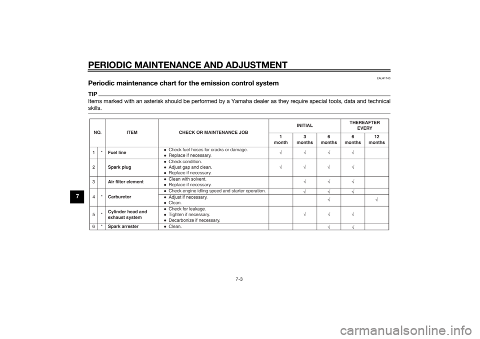
EAU41743
Periodic maintenance chart for the emission control systemTIPItems marked with an asterisk should be performed by a Yamaha dealer as they require special tools, data and technical
skills.NO. ITEM CHECK OR MAINTENANCE JOB INITIAL
THEREAFTER
EVERY
1
month 3
months 6
months 6
months 12
months
1* Fuel line
Check fuel hoses for cracks or damage.Replace if necessary.
2 Spark plugCheck condition.Adjust gap and clean.Replace if necessary.
3 Air filter elementClean with solvent.Replace if necessary.
4* CarburetorCheck engine idling speed and starter operation.Adjust if necessary.Clean.
5* Cylinder head and
exhaust systemCheck for leakage.Tighten if necessary.Decarbonize if necessary.
6* Spark arresterClean.
U2SA80E0.book Page 3 Monday, June 3, 2013 5:25 PM
Page 47 of 76
PERIODIC MAINTENANCE AND ADJUSTMENT
7-6
7
EAU19605
Checking the spark plugThe spark plug is an important engine
component, which is easy to check.
Since heat and deposits will cause any
spark plug to slowly erode, the spark
plug should be removed and checked
in accordance with the periodic main-
tenance and lubrication chart. In addi-
tion, the condition of the spark plug
can reveal the condition of the engine.
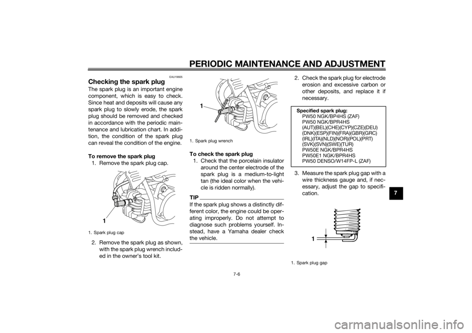
To remove the spark plu g
1. Remove the spark plug cap.
2. Remove the spark plug as shown, with the spark plug wrench includ-
ed in the owner’s tool kit. To check the spark plu
g
1. Check that the porcelain insulator around the center electrode of the
spark plug is a medium-to-light
tan (the ideal color when the vehi-
cle is ridden normally).
TIPIf the spark plug shows a distinctly dif-
ferent color, the engine could be oper-
ating improperly. Do not attempt to
diagnose such problems yourself. In-
stead, have a Yamaha dealer check
the vehicle.
2. Check the spark plug for electrodeerosion and excessive carbon or
other deposits, and replace it if
necessary.
3. Measure the spark plug gap with a wire thickness gauge and, if nec-
essary, adjust the gap to specifi-
cation.
1. Spark plug cap
1
1. Spark plug wrench
1
Specified spark plu g:
PW50 NGK/BP4HS (ZAF)
PW50 NGK/BPR4HS
(AUT)(BEL)(CHE)(CYP)(CZE)(DEU)
(DNK)(ESP)(FIN)(FRA)(GBR)(GRC)
(IRL)(ITA)(NLD)(NOR)(POL)(PRT)
(SVK)(SVN)(SWE)(TUR)
PW50E NGK/BPR4HS
PW50E1 NGK/BPR4HS
PW50 DENSO/W14FP-L (ZAF)
1. Spark plug gap
1
U2SA80E0.book Page 6 Monday, June 3, 2013 5:25 PM
Page 48 of 76
PERIODIC MAINTENANCE AND ADJUSTMENT
7-7
7To install the spark plu
g
1. Clean the surface of the spark plug gasket and its mating sur-
face, and then wipe off any grime
from the spark plug threads.
2. Install the spark plug with the spark plug wrench, and then tight-
en it to the specified torque.
TIPIf a torque wrench is not available
when installing a spark plug, a good
estimate of the correct torque is 1/4–
1/2 turn past finger tight. However, the
spark plug should be tightened to the
specified torque as soon as possible.3. Install the spark plug cap.
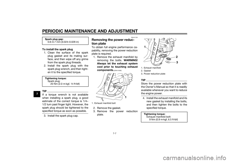
EAU41104
Removin g the power re duc-
tion plateTo obtain full engine performance ca-
pability, removing the power reduction
plate is required.
1. Remove the exhaust manifold by removing the bolts. WARNING!
Always let the exhaust system
cool prior to touching exhaust
components.
[EWA14582]
2. Remove the gasket.
3. Remove the power reduction plate.
TIPStore the power reduction plate with
the Owner’s Manual so that it is readily
available whenever you want to reduce
the engine power.4. Install the exhaust manifold and itsnew gasket by installing the bolts,
and then tighten the bolts to the
specified torque.
Spark plu g g ap:
0.6–0.7 mm (0.024–0.028 in)
Ti ghtenin g torque:
Spark plug: 20 Nm (2.0 m·kgf, 14 ft·lbf)
1. Exhaust manifold bolt
1
1. Exhaust manifold
2. Gasket
3. Power reduction plateTightenin g torque:
Exhaust manifold bolt: 9 Nm (0.9 m·kgf, 6.5 ft·lbf)1
23
U2SA80E0.book Page 7 Monday, June 3, 2013 5:25 PM