check YAMAHA RHINO 700 2010 Service Manual
[x] Cancel search | Manufacturer: YAMAHA, Model Year: 2010, Model line: RHINO 700, Model: YAMAHA RHINO 700 2010Pages: 498, PDF Size: 11.87 MB
Page 336 of 498
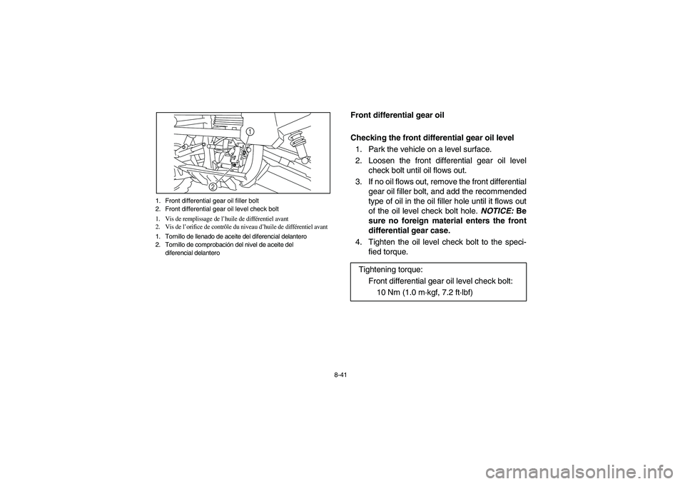
8-41 1. Front differential gear oil filler bolt
2. Front differential gear oil level check bolt
1. Vis de remplissage de l’huile de différentiel avant
2. Vis de l’orifice de contrôle du niveau d’huile de différentiel avant
1. Tornillo de llenado de aceite del diferencial delantero
2. Tornillo de comprobación del nivel de aceite del
diferencial delantero
1
2
5B410014
Front differential gear oil
Checking the front differential gear oil level
1. Park the vehicle on a level surface.
2. Loosen the front differential gear oil level
check bolt until oil flows out.
3. If no oil flows out, remove the front differential
gear oil filler bolt, and add the recommended
type of oil in the oil filler hole until it flows out
of the oil level check bolt hole. NOTICE: Be
sure no foreign material enters the front
differential gear case.
4. Tighten the oil level check bolt to the speci-
fied torque.
Tightening torque:
Front differential gear oil level check bolt:
10 Nm (1.0 m·kgf, 7.2 ft·lbf)
EE.book Page 41 Monday, January 19, 2009 5:30 PM
Page 340 of 498
8-45
5. Refill with the specified amount of the recom-
mended front differential gear oil. NOTICE:
Be sure no foreign material enters the
front differential gear case.
6. Reinstall the oil filler bolt, and then tighten it to
the specified torque.
7. Check for oil leakage. If oil leakage is found,
check for the cause. Recommended oil:
SAE 80 API GL-4 Hypoid gear oil
Oil quantity:
0.30 L (0.32 US qt, 0.26 Imp.qt)
Tightening torque:
Front differential gear oil filler bolt:
23 Nm (2.3 m·kgf, 17 ft·lbf)
EE.book Page 45 Monday, January 19, 2009 5:30 PM
Page 342 of 498
8-47
5B410013
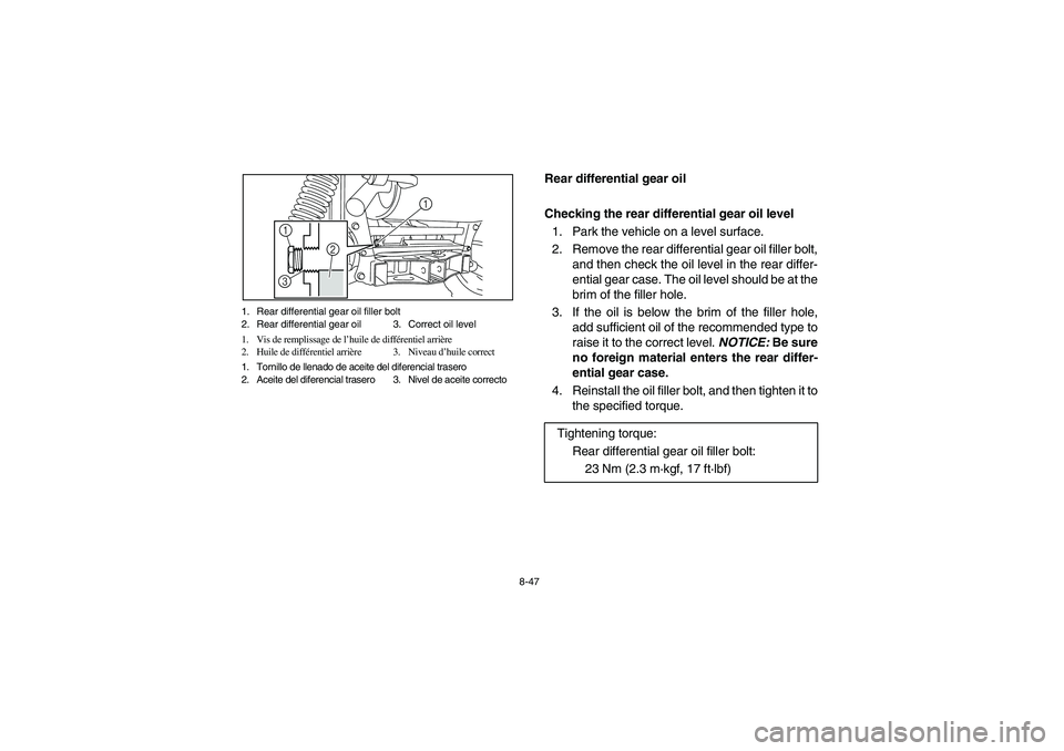
Rear differential gear oil
Checking the rear differential gear oil level
1. Park the vehicle on a level surface.
2. Remove the rear differential gear oil filler bolt,
and then check the oil level in the rear differ-
ential gear case. The oil level should be at the
brim of the filler hole.
3. If the oil is below the brim of the filler hole,
add sufficient oil of the recommended type to
raise it to the correct level. NOTICE: Be sure
no foreign material enters the rear differ-
ential gear case.
4. Reinstall the oil filler bolt, and then tighten it to
the specified torque.
Tightening torque:
Rear differential gear oil filler bolt:
23 Nm (2.3 m·kgf, 17 ft·lbf)
1. Rear differential gear oil filler bolt
2. Rear differential gear oil 3. Correct oil level
1. Vis de remplissage de l’huile de différentiel arrière
2. Huile de différentiel arrière 3. Niveau d’huile correct
1. Tornillo de llenado de aceite del diferencial trasero
2. Aceite del diferencial trasero 3. Nivel de aceite correcto
1
2
31
EE.book Page 47 Monday, January 19, 2009 5:30 PM
Page 346 of 498
8-51
6. Reinstall the oil filler bolt, and then tighten it to
the specified torque.
7. Check for oil leakage. If oil leakage is found,
check for the cause. Tightening torque:
Rear differential gear oil filler bolt:
23 Nm (2.3 m·kgf, 17 ft·lbf)
EE.book Page 51 Monday, January 19, 2009 5:30 PM
Page 348 of 498
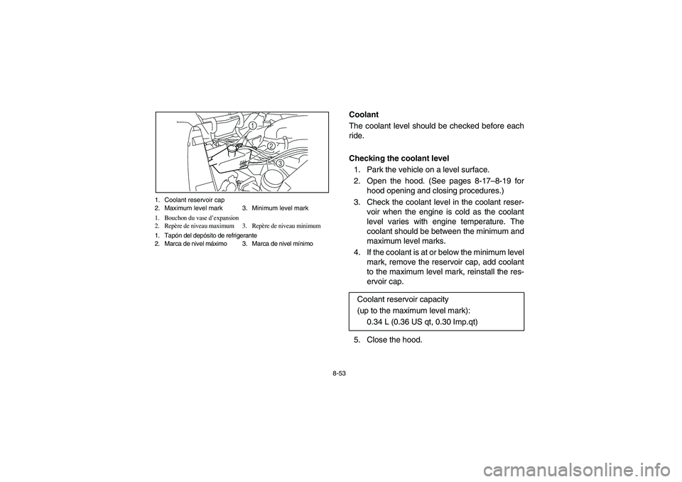
8-53 1. Coolant reservoir cap
2. Maximum level mark 3. Minimum level mark
1. Bouchon du vase d’expansion
2. Repère de niveau maximum 3. Repère de niveau minimum
1. Tapón del depósito de refrigerante
2. Marca de nivel máximo 3. Marca de nivel mínimo
3 2 1
5B410015
Coolant
The coolant level should be checked before each
ride.
Checking the coolant level
1. Park the vehicle on a level surface.
2. Open the hood. (See pages 8-17–8-19 for
hood opening and closing procedures.)
3. Check the coolant level in the coolant reser-
voir when the engine is cold as the coolant
level varies with engine temperature. The
coolant should be between the minimum and
maximum level marks.
4. If the coolant is at or below the minimum level
mark, remove the reservoir cap, add coolant
to the maximum level mark, reinstall the res-
ervoir cap.
5. Close the hood.Coolant reservoir capacity
(up to the maximum level mark):
0.34 L (0.36 US qt, 0.30 Imp.qt)
EE.book Page 53 Monday, January 19, 2009 5:30 PM
Page 350 of 498
8-55
Changing the coolant
The coolant must be changed by a Yamaha dealer
at the intervals specified in the periodic mainte-
nance and lubrication chart.
Adding water instead of coolant lowers the anti-
freeze content of the coolant. If water is used in-
stead of coolant, have a Yamaha dealer check the
antifreeze content of the coolant as soon as possi-
ble.
The radiator fan is automatically switched on or off
according to the coolant temperature in the radia-
tor.NOTICEMix antifreeze with distilled water only. Howev-
er, if distilled water is not available, soft water
may be used for refilling.If your vehicle overheats, see page 8-154 for in-
structions.
EE.book Page 55 Monday, January 19, 2009 5:30 PM
Page 352 of 498
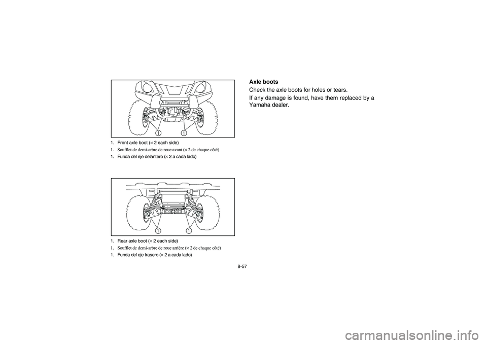
8-57 1. Front axle boot (× 2 each side)
1. Soufflet de demi-arbre de roue avant (× 2 de chaque côté)
1. Funda del eje delantero (× 2 a cada lado)
11
1. Rear axle boot (× 2 each side)
1. Soufflet de demi-arbre de roue arrière (× 2 de chaque côté)
1. Funda del eje trasero (× 2 a cada lado)
1
1
EVU00740
Axle boots
Check the axle boots for holes or tears.
If any damage is found, have them replaced by a
Yamaha dealer.
EE.book Page 57 Monday, January 19, 2009 5:30 PM
Page 360 of 498
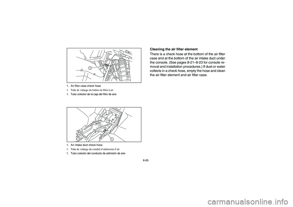
8-65 1. Air filter case check hose
1. Tube de vidange du boîtier de filtre à air
1. Tubo colector de la caja del filtro de aire
1
1. Air intake duct check hose
1. Tube de vidange du conduit d’admission d’air
1. Tubo colector del conducto de admisión de aire
1
5B410016
Cleaning the air filter element
There is a check hose at the bottom of the air filter
case and at the bottom of the air intake duct under
the console. (See pages 8-21–8-23 for console re-
moval and installation procedures.) If dust or water
collects in a check hose, empty the hose and clean
the air filter element and air filter case.
EE.book Page 65 Monday, January 19, 2009 5:30 PM
Page 370 of 498
8-75
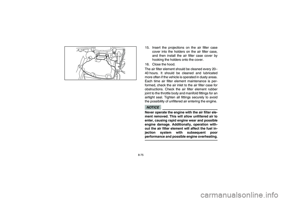
15. Insert the projections on the air filter case
cover into the holders on the air filter case,
and then install the air filter case cover by
hooking the holders onto the cover.
16. Close the hood.
The air filter element should be cleaned every 20–
40 hours. It should be cleaned and lubricated
more often if the vehicle is operated in dusty areas.
Each time air filter element maintenance is per-
formed, check the air inlet to the air filter case for
obstructions. Check the air filter element rubber
joint to the throttle body and manifold fittings for an
airtight seal. Tighten all fittings securely to avoid
the possibility of unfiltered air entering the engine.NOTICENever operate the engine with the air filter ele-
ment removed. This will allow unfiltered air to
enter, causing rapid engine wear and possible
engine damage. Additionally, operation with-
out the air filter element will affect the fuel in-
jection system with subsequent poor
performance and possible engine overheating.
EE.book Page 75 Monday, January 19, 2009 5:30 PM
Page 372 of 498
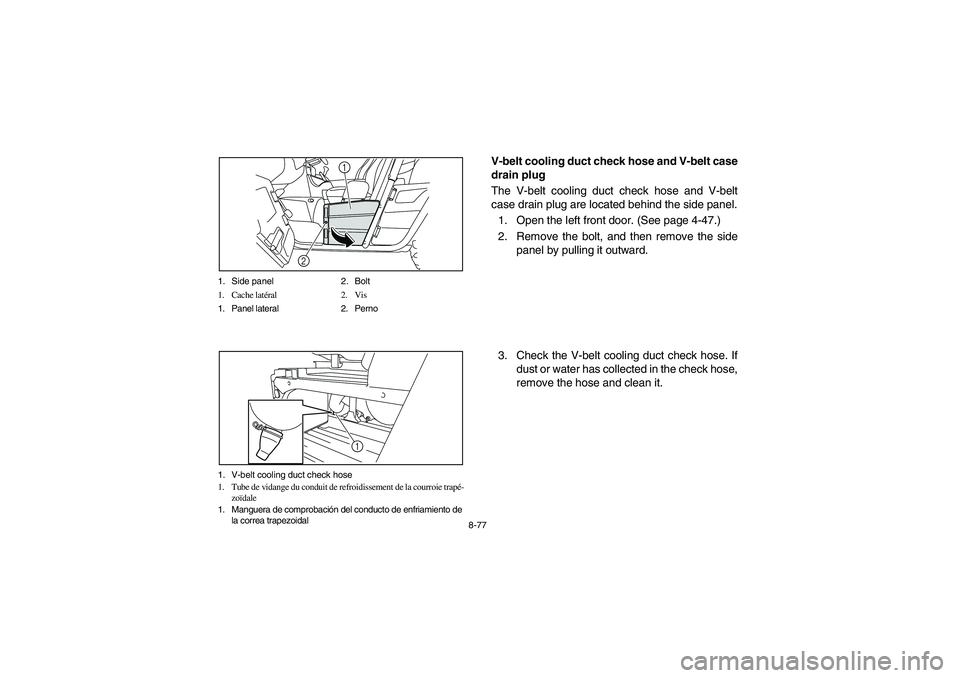
8-77 1. Side panel 2. Bolt
1. Cache latéral 2. Vis
1. Panel lateral 2. Perno
1
2
1. V-belt cooling duct check hose
1. Tube de vidange du conduit de refroidissement de la courroie trapé-
zoïdale
1. Manguera de comprobación del conducto de enfriamiento de
la correa trapezoidal
1
V-belt cooling duct check hose and V-belt case
drain plug
The V-belt cooling duct check hose and V-belt
case drain plug are located behind the side panel.
1. Open the left front door. (See page 4-47.)
2. Remove the bolt, and then remove the side
panel by pulling it outward.
3. Check the V-belt cooling duct check hose. If
dust or water has collected in the check hose,
remove the hose and clean it.
EE.book Page 77 Monday, January 19, 2009 5:30 PM