YAMAHA SLIDER 50 2006 User Guide
Manufacturer: YAMAHA, Model Year: 2006, Model line: SLIDER 50, Model: YAMAHA SLIDER 50 2006Pages: 80, PDF Size: 2.06 MB
Page 11 of 80
GIVE SAFETY THE RIGHT OF WAY
1
EAU03099
Further safe-riding points•
Be sure to signal clearly when making turns.
•
Braking can be extremely difficult on a wet road. Avoid hard braking, because the scooter could slide.
Apply the brakes slowly when stopping on a wet surface.
•
Slow down as you approach a corner or turn. Once you have completed a turn, accelerate slowly.
•
Be careful when passing parked cars. A driver might not see you and open a door in your path.
•
Railroad crossings, streetcar rails, iron plates on road construction sites, and manhole covers become
extremely slippery when wet. Slow down and cross them with caution. Keep the scooter upright, otherwise
it could slide out from under you.
•
The brake pads could get wet when you wash the scooter. After washing the scooter, check the brakes
before riding.
•
Always wear a helmet, gloves, trousers (tapered around the cuff and ankle so they do not flap), and a
bright colored jacket.
•
Do not carry too much luggage on the scooter. An overloaded scooter is unstable.
1-2
Page 12 of 80

Page 13 of 80
EAU01161
DESCRIPTION
Left view .............................................................................................. 2-1
Right view ........................................................................................... 2-2
2
Page 14 of 80
2
DESCRIPTIONLeft view
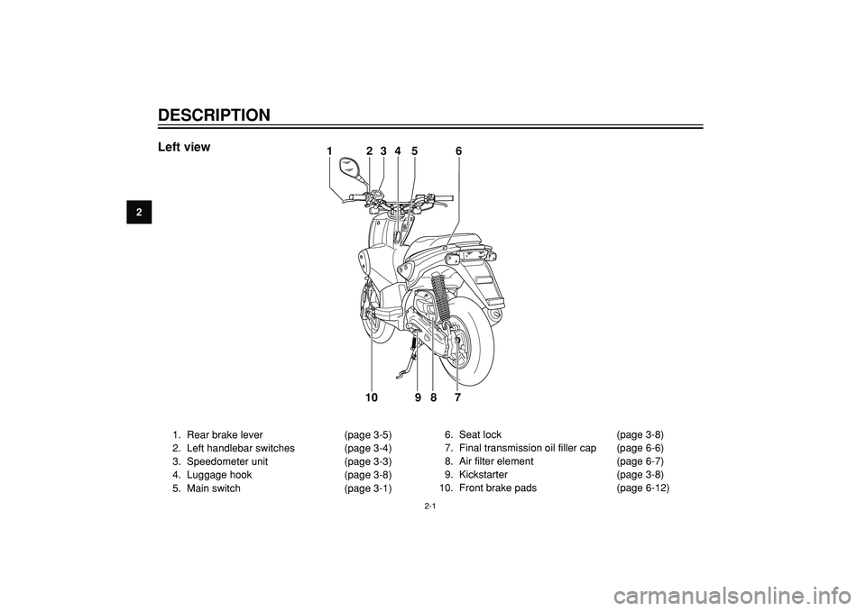
12345 6
7 8 9 10
1. Rear brake lever (page 3-5)
2. Left handlebar switches (page 3-4)
3. Speedometer unit (page 3-3)
4. Luggage hook (page 3-8)
5. Main switch (page 3-1)6. Seat lock (page 3-8)
7. Final transmission oil filler cap (page 6-6)
8. Air filter element (page 6-7)
9. Kickstarter (page 3-8)
10. Front brake pads (page 6-12)
2-1
Page 15 of 80
2
DESCRIPTION
Right view
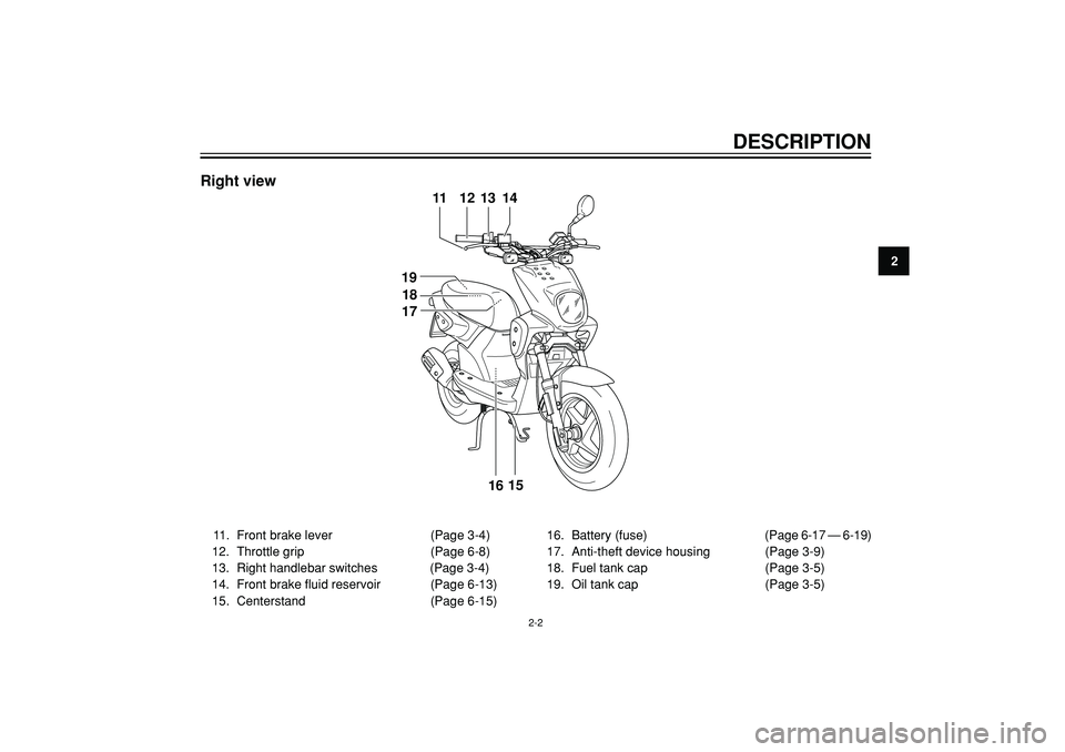
11. Front brake lever (Page 3-4)
12. Throttle grip (Page 6-8)
13. Right handlebar switches (Page 3-4)
14. Front brake fluid reservoir (Page 6-13)
15. Centerstand (Page 6-15)16. Battery (fuse) (Page 6-17 — 6-19)
17. Anti-theft device housing (Page 3-9)
18. Fuel tank cap (Page 3-5)
19. Oil tank cap (Page 3-5)
11 12 13 14
15
16 18 19
17
2-2
Page 16 of 80

Page 17 of 80
EAU00027
INSTRUMENT AND CONTROL FUNCTIONSMain switch / steering lock .................................................................. 3-1
Indicator and warning lights ................................................................ 3-2
Speedometer unit ................................................................................ 3-3
Handlebar switches ............................................................................. 3-4
Front brake lever ................................................................................. 3-4
Rear brake lever ................................................................................. 3-5
Fuel and 2-stroke engine oil tank caps ............................................... 3-5
Fuel ..................................................................................................... 3-6
2-stroke engine oil ............................................................................... 3-7
Catalytic converter .............................................................................. 3-7
Starter (choke) lever ........................................................................... 3-7
Kickstarter ........................................................................................... 3-8
Seat ..................................................................................................... 3-8
Luggage hook ..................................................................................... 3-8
Anti-theft device housing ..................................................................... 3-9
3
Page 18 of 80
3
INSTRUMENT AND CONTROL FUNCTIONS
EAU00029
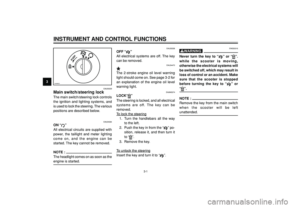
Main switch/steering lockThe main switch/steering lock controls
the ignition and lighting systems, and
is used to lock the steering. The various
positions are described below.
PUSH
ZAUM0332
EAU00038
OFF “
”
All electrical systems are off. The key
can be removed.
EAU04470
*The 2-stroke engine oil level warning
light should come on. See page 3-2 for
an explanation of the engine oil level
warning light.
EAUM0074
LOCK“
”
The steering is locked, and all electrical
systems are off. The key can be
removed.
To lock the steering
1. Turn the handlebars all the way
to the left.
2. Push the key in from the “
” po-
sition, release it, and then turn it
to “
”.
3. Remove the key.
To unlock the steering
Insert the key and turn it to “
”.
EW000016
Never turn the key to “
” or “
”.
while the scooter is moving,
otherwise the electrical systems will
be switched off, which may result in
loss of control or an accident. Make
sure that the scooter is stopped
before turning the key to “
” or
“
”.
NOTE :
Remove the key from the main switch
when the scooter will be leftunattended.
3-1
EAU04384
ON “
”
All electrical circuits are supplied with
power, the taillight and meter lighting
come on, and the engine can be
started. The key cannot be removed.
NOTE :
The headlight comes on as soon as theengine is started.
Page 19 of 80
INSTRUMENT AND CONTROL FUNCTIONS
3
12 34
ZAUM0522
EAU03034
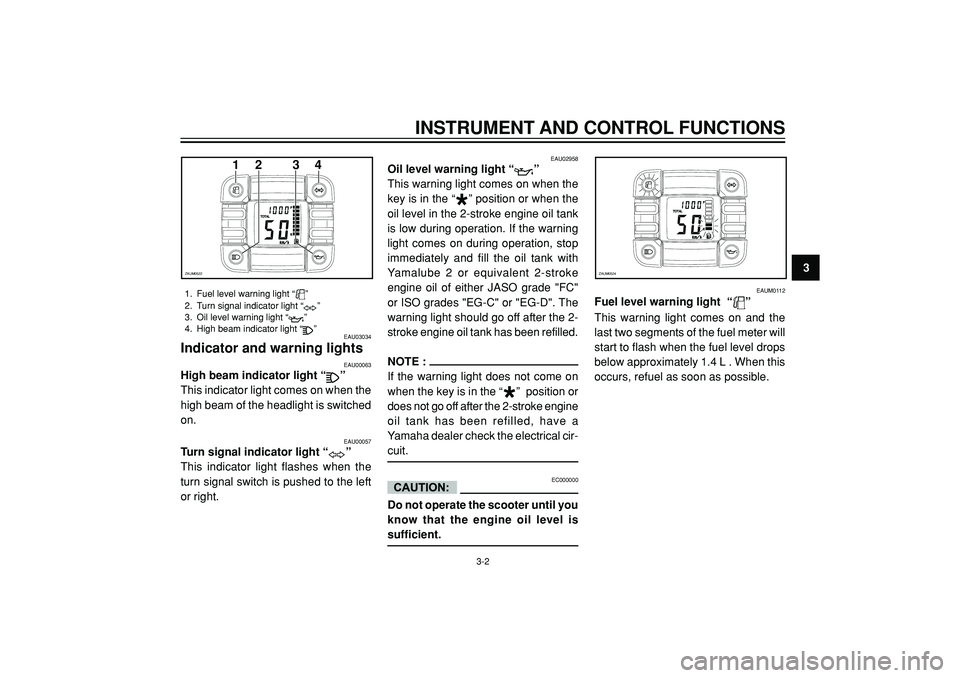
Indicator and warning lights
EAU00057
Turn signal indicator light “
”
This indicator light flashes when the
turn signal switch is pushed to the left
or right.
1. Fuel level warning light “
”
2. Turn signal indicator light “
”
3. Oil level warning light “
”
4. High beam indicator light “”
EAU00063
High beam indicator light “
”
This indicator light comes on when the
high beam of the headlight is switched
on.
EAU02958
Oil level warning light “
”
This warning light comes on when the
key is in the “
*
” position or when the
oil level in the 2-stroke engine oil tank
is low during operation. If the warning
light comes on during operation, stop
immediately and fill the oil tank with
Yamalube 2 or equivalent 2-stroke
engine oil of either JASO grade "FC"
or ISO grades "EG-C" or "EG-D". The
warning light should go off after the 2-
stroke engine oil tank has been refilled.
NOTE :
If the warning light does not come on
when the key is in the “
*
” position or
does not go off after the 2-stroke engine
oil tank has been refilled, have a
Yamaha dealer check the electrical cir-
cuit.
EC000000
Do not operate the scooter until you
know that the engine oil level issufficient.
3-2
ZAUM0524
EAUM0112
Fuel level warning light “
”
This warning light comes on and the
last two segments of the fuel meter will
start to flash when the fuel level drops
below approximately 1.4 L . When this
occurs, refuel as soon as possible.
Page 20 of 80
3
INSTRUMENT AND CONTROL FUNCTIONS
12 3
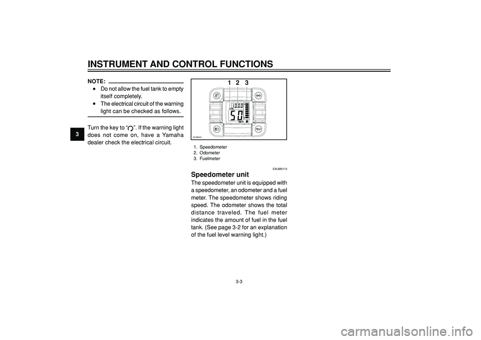
ZAUM05231. Speedometer
2. Odometer
3. Fuelmeter
3-3
NOTE:•
Do not allow the fuel tank to empty
itself completely.
•
The electrical circuit of the warninglight can be checked as follows.
Turn the key to “
”. If the warning light
does not come on, have a Yamaha
dealer check the electrical circuit.
EAUM0113
Speedometer unitThe speedometer unit is equipped with
a speedometer, an odometer and a fuel
meter. The speedometer shows riding
speed. The odometer shows the total
distance traveled. The fuel meter
indicates the amount of fuel in the fuel
tank. (See page 3-2 for an explanation
of the fuel level warning light.)