warning YAMAHA SR400 2014 User Guide
[x] Cancel search | Manufacturer: YAMAHA, Model Year: 2014, Model line: SR400, Model: YAMAHA SR400 2014Pages: 88, PDF Size: 2.51 MB
Page 27 of 88

INSTRUMENT AND CONTROL FUNCTIONS
3-12
1
234
5
6
7
8
9
10
11
12
EAU14883
Adjusting the shock absorber
assemblies
WARNING
EWA10211
Always adjust both shock absorber
assemblies equally, otherwise poor
handling and loss of stability mayresult.
Each shock absorber assembly is
equipped with a spring preload adjust-
ing ring.NOTICE
ECA10102
To avoid damaging the mechanism,
do not attempt to turn beyond themaximum or minimum settings.
Adjust the spring preload as follows.
To increase the spring preload and
thereby harden the suspension, turn
the adjusting ring on each shock ab-
sorber assembly in direction (a). To de-
crease the spring preload and thereby
soften the suspension, turn the adjust-
ing ring on each shock absorber as-
sembly in direction (b).
Align the appropriate notch in the ad-
justing ring with the position indicator on the shock absorber.
EAU15306
SidestandThe sidestand is located on the left side
of the frame. Raise the sidestand or
lower it with your foot while holding the
vehicle upright.TIPThe built-in sidestand switch is part of
the ignition circuit cut-off system, which
cuts the ignition in certain situations.
(See the following section for an expla-
nation of the ignition circuit cut-off sys-tem.)
WARNING
EWA10242
The vehicle must not be ridden with
the sidestand down, or if the sides-
tand cannot be properly moved up
(or does not stay up), otherwise the
sidestand could contact the ground
and distract the operator, resulting
in a possible loss of control.
Yamaha’s ignition circuit cut-off
system has been designed to assist
the operator in fulfilling the respon-
sibility of raising the sidestand be-
fore starting off. Therefore, check
this system regularly and have a
1. Spring preload adjusting ringSpring preload setting:
Minimum (soft):
1
Standard: 1
Maximum (hard): 5
1
2
3
4
5
1
(a) (b)
2RD-9-E0.book 12 ページ 2013年11月28日 木曜日 午後4時18分
Page 29 of 88

INSTRUMENT AND CONTROL FUNCTIONS
3-14
1
234
5
6
7
8
9
10
11
12
With the engine turned off:
1. Move the sidestand down.
2. Make sure that the engine stop switch is set to “
3. Turn the key on.
4. Shift the transmission into the neutral position.
5. Push the kick starter lever down.
Does the engine start?
With the engine still running:
6. Move the sidestand up.
7. Keep the clutch lever pulled.
8. Shift the transmission into gear.
9. Move the sidestand down.
Does the engine stall?
After the engine has stalled:
10. Move the sidestand up.
11. Keep the clutch lever pulled.
12. Push the kick starter lever down.
Does the engine start?
The system is OK. The motorcycle can be ridden.
YES NO YES NO YES NO
The neutral switch may not be working correctly.
The motorcycle should not be ridden until
checked by a Yamaha dealer.
The clutch switch may not be working correctly.
The motorcycle should not be ridden until
checked by a Yamaha dealer.The sidestand switch may not be working correctly.
The motorcycle should not be ridden until
checked by a Yamaha dealer.The vehicle must be placed on the center-
stand during this inspection. If a malfunction is noted, have a Yamaha
dealer check the system before riding.
WARNING
”.
2RD-9-E0.book 14 ページ 2013年11月28日 木曜日 午後4時18分
Page 30 of 88

4-1
1
2
34
5
6
7
8
9
10
11
12
FOR YOUR SAFETY – PRE-OPERATION CHECKS
EAU15598
Inspect your vehicle each time you use it to make sure the vehi cle is in safe operating condition. Always follow the inspection
and maintenance procedures and schedules described in the Owner’s Manual.
WARNING
EWA11152
Failure to inspect or maintain the vehicle properly increases the possibility of an accident or equipment damage.
Do not operate the vehicle if you find any problem. If a problem cannot be corrected by the procedures provided inthis manual, have the vehicle inspected by a Yamaha dealer.
Before using this vehicle, check the following points:
ITEM CHECKS PAGE
Fuel Check fuel level in fuel tank.
Refuel if necessary.
Check fuel line for leakage.
Check fuel tank breather hose for
obstructions, cracks or damage, and check
hose connection. 3-7, 3-9
Engine oil Check oil level in oil tank.
If necessary, add recommended oil to specified level.
Check vehicle for oil leakage. 6-9
Front brake Check operation.
If soft or spongy, have Yamaha dealer bleed hydraulic system.
Check lever free play.
Adjust if necessary.
Check brake pads for wear.
Replace if necessary.
Check fluid level in reservoir.
If necessary, add specified brake fluid to specified level.
Check hydraulic system for leakage. 6-17, 6-20
Rear brake Check operation.
Check pedal free play.
Adjust if necessary. 6-18, 6-20
2RD-9-E0.book 1 ページ 2013年11月28日 木曜日 午後4時18分
Page 32 of 88

5-1
1
2
3
45
6
7
8
9
10
11
12
OPERATION AND IMPORTANT RIDING POINTS
EAU15952
Read the Owner’s Manual carefully to
become familiar with all controls. If
there is a control or function you do not
understand, ask your Yamaha dealer.
WARNING
EWA10272
Failure to familiarize yourself with
the controls can lead to loss of con-
trol, which could cause an accidentor injury.
EAU59360
TIPThis model is equipped with:
a lean angle sensor to stop the en-
gine in case of a turnover. In this
case, turn the key to “OFF” and
then to “ON”. Failing to do so will
prevent the engine from starting
even though the engine will crank
when pushing the kick starter lever
down.
an engine auto-stop system. The
engine stops automatically if left
idling for 20 minutes. If the engine
stops, simply push the kick starterlever down to restart the engine.
EAU59530
Starting the engineIn order for the ignition circuit cut-off
system to enable starting, one of the
following conditions must be met:
The transmission is in the neutral
position.
The transmission is in gear with
the clutch lever pulled and the sid-
estand up.
See page 3-13 for more informa-
tion.
1. Turn the key to “ON” and set the engine stop switch to “ ”.
The engine trouble warning light
and fuel level warning light should
come on for a few seconds, then
go off.
NOTICE
ECA16712
If the warning light does not come
on initially when the key is turned to
“ON”, or if the warning light remains
on, see page 3-2 for the warning lightcircuit check.
2. Shift the transmission into the neu- tral position. The neutral indicator
light should come on. If not, ask a
2RD-9-E0.book 1 ページ 2013年11月28日 木曜日 午後4時18分
Page 35 of 88

OPERATION AND IMPORTANT RIDING POINTS
5-4
1
2
3
456
7
8
9
10
11
12
r/min.
1600 km (1000 mi) and beyond
The vehicle can now be operated nor-
mally.
NOTICE
ECA10311
Keep the engine speed out of
the tachometer red zone.
If any engine trouble should oc-
cur during the engine break-in
period, immediately have a
Yamaha dealer check the vehi-cle.
EAU17214
ParkingWhen parking, stop the engine, and
then remove the key from the main
switch.
WARNING
EWA10312
Since the engine and exhaust
system can become very hot,
park in a place where pedestri-
ans or children are not likely to
touch them and be burned.
Do not park on a slope or on soft
ground, otherwise the vehicle
may overturn, increasing the
risk of a fuel leak and fire.
Do not park near grass or other
flammable materials whichmight catch fire.
2RD-9-E0.book 4 ページ 2013年11月28日 木曜日 午後4時18分
Page 36 of 88

6-1
1
2
3
4
56
7
8
9
10
11
12
PERIODIC MAINTENANCE AND ADJUSTMENT
EAU17245
Periodic inspection, adjustment, and lu-
brication will keep your vehicle in the
safest and most efficient condition pos-
sible. Safety is an obligation of the vehi-
cle owner/operator. The most important
points of vehicle inspection, adjust-
ment, and lubrication are explained on
the following pages.
The intervals given in the periodic
maintenance charts should be simply
considered as a general guide under
normal riding conditions. However, de-
pending on the weather, terrain, geo-
graphical location, and individual use,
the maintenance intervals may need to
be shortened.
WARNING
EWA10322
Failure to properly maintain the ve-
hicle or performing maintenance ac-
tivities incorrectly may increase
your risk of injury or death during
service or while using the vehicle. If
you are not familiar with vehicle ser-
vice, have a Yamaha dealer performservice.
WARNING
EWA15123
Turn off the engine when performing
maintenance unless otherwise
specified.
A running engine has moving
parts that can catch on body
parts or clothing and electrical
parts that can cause shocks or
fires.
Running the engine while ser-
vicing can lead to eye injury,
burns, fire, or carbon monoxide
poisoning – possibly leading to
death. See page 1-2 for more in-
formation about carbon monox-ide.WARNING
EWA15461
Brake discs, calipers, drums, and
linings can become very hot during
use. To avoid possible burns, let
brake components cool beforetouching them.
EAU17303
Emission controls not only function to
ensure cleaner air, but are also vital to
proper engine operation and maximum
performance. In the following periodic
maintenance charts, the services relat-
ed to emissions control are grouped
separately. These services require
specialized data, knowledge, and
equipment. Maintenance, replacement,
or repair of the emission control devic-
es and systems may be performed by
any repair establishment or individual
that is certified (if applicable). Yamaha
dealers are trained and equipped to
perform these particular services.
2RD-9-E0.book 1 ページ 2013年11月28日 木曜日 午後4時18分
Page 44 of 88
PERIODIC MAINTENANCE AND ADJUSTMENT
6-9
1
2
3
4
56
7
8
9
10
11
12 spark plug wrench, and then tight-
en it to the specified torque.
TIPIf a torque wrench is not available when
installing a spark plug, a good estimate
of the correct torque is 1/4–1/2 turn
past finger tight. However, the spark
plug should be tightened to the speci-fied torque as soon as possible.
3. Install the spark plug cap.
EAU59622
Engine oil and oil filter
elementThe engine oil level should be checked
before each ride. In addition, the oil
must be changed and the oil filter ele-
ment replaced at the intervals specified
in the periodic maintenance and lubri-
cation chart.
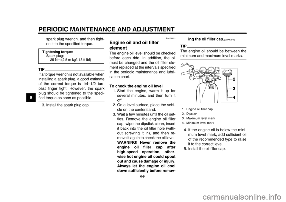
To check the engine oil level1. Start the engine, warm it up for several minutes, and then turn it
off.
2. On a level surface, place the vehi- cle on the centerstand.
3. Wait a few minutes until the oil set- tles. Remove the engine oil filler
cap, wipe the dipstick clean, insert
it back into the oil filler hole (with-
out screwing it in), and then re-
move it again to check the oil level.
WARNING! Never remove the
engine oil filler cap after
high-speed operation, other-
wise hot engine oil could spout
out and cause damage or injury.
Always let the engine oil cool
down sufficiently before remov- ing the oil filler cap.
[EWA17640]
TIPThe engine oil should be between theminimum and maximum level marks.
4. If the engine oil is below the mini- mum level mark, add sufficient oil
of the recommended type to raise
it to the correct level.
5. Install the oil filler cap.
Tightening torque: Spark plug:25 Nm (2.5 m·kgf, 18 ft·lbf)
1. Engine oil filler cap
2. Dipstick
3. Maximum level mark
4. Minimum level mark
3
4
12
2RD-9-E0.book 9 ページ 2013年11月28日 木曜日 午後4時18分
Page 49 of 88

PERIODIC MAINTENANCE AND ADJUSTMENT
6-14
1
2
3
4
567
8
9
10
11
12
EAU59632
TiresTires are the only contact between the
vehicle and the road. Safety in all con-
ditions of riding depends on a relatively
small area of road contact. Therefore, it
is essential to maintain the tires in good
condition at all times and replace them
at the appropriate time with the speci-
fied tires.
Tire air pressure
The tire air pressure should be checked
and, if necessary, adjusted before each
ride.
WARNING
EWA10504
Operation of this vehicle with im-
proper tire pressure may cause se-
vere injury or death from loss of
control.
The tire air pressure must be
checked and adjusted on cold
tires (i.e., when the temperature
of the tires equals the ambient
temperature).
The tire air pressure must be ad-
justed in accordance with the
riding speed and with the total weight of rider, passenger, car-
go, and accessories approved
for this model.WARNING
EWA10512
Never overload your vehicle. Opera-
tion of an overloaded vehicle couldcause an accident.
Tire inspection
The tires must be checked before each
ride. If the center tread depth reaches
the specified limit, if the tire has a nail or
glass fragments in it, or if the sidewall is
cracked, have a Yamaha dealer re-
place the tire immediately.
TIPThe tire tread depth limits may differ
from country to country. Always complywith the local regulations.
Tire air pressure (measured on cold
tires):
Up to 90 kg (198 lbs) load:Front: 175 kPa (1.75 kgf/cm
2, 25 psi)
Rear: 200 kPa (2.00 kgf/cm2, 29 psi)
90 kg (198 lbs) to maximum load:
Front: 200 kPa (2.00 kgf/cm2, 29 psi)
Rear:
225 kPa (2.25 kgf/cm2, 33 psi)
Maximum load*: 150 kg (331 lb)
* Total weight of rider, passenger, car- go and accessories
1. Tire sidewall
2. Tire tread depthMinimum tire tread depth (front and
rear): 1.6 mm (0.06 in)
2RD-9-E0.book 14 ページ 2013年11月28日 木曜日 午後4時18分
Page 50 of 88

PERIODIC MAINTENANCE AND ADJUSTMENT
6-15
1
2
3
4
56
7
8
9
10
11
12 Tire information
This motorcycle is equipped with tube
tires.
Tires age, even if they have not been
used or have only been used occasion-
ally. Cracking of the tread and sidewall
rubber, sometimes accompanied by
carcass deformation, is an evidence of
ageing. Old and aged tires shall be
checked by tire specialists to ascertain
their suitability for further use.
WARNING
EWA10462
The front and rear tires should be of
the same make and design, other-
wise the handling characteristics of
the vehicle may be different, whichcould lead to an accident.
After extensive tests, only the tires list-
ed below have been approved for this
model by Yamaha Motor Co., Ltd.
WARNING
EWA10572
Have a Yamaha dealer replace
excessively worn tires. Besides
being illegal, operating the mo-
torcycle with excessively worn
tires decreases riding stability
and can lead to loss of control.
The replacement of all wheel-
and brake-related parts, includ-
ing the tires, should be left to a
Yamaha dealer, who has the
necessary professional knowl-
edge and experience.
It is not recommended to patch
a punctured tube. If unavoid-
able, however, patch the tube
very carefully and replace it as
soon as possible with a high-quality product.
Ride at moderate speeds after
changing a tire since the tire
surface must first be “broken
in” for it to develop its optimalcharacteristics.
Front tire:
Size:90/100-18M/C 54S
Manufacturer/model:
METZELER/ME77 Front
Rear tire: Size:
110/90-18M/C 61S
Manufacturer/model: METZELER/ME77
2RD-9-E0.book 15 ページ 2013年11月28日 木曜日 午後4時18分
Page 51 of 88
PERIODIC MAINTENANCE AND ADJUSTMENT
6-16
1
2
3
4
567
8
9
10
11
12
EAU21944
Spoke wheels
WARNING
EWA10611
The wheels on this model are not de-
signed for use with tubeless tires.
Do not attempt to use tubeless tireson this model.
To maximize the performance, durabil-
ity, and safe operation of your motorcy-
cle, note the following points regarding
the specified wheels.
The wheel rims should be checked
for cracks, bends, warpage or oth-
er damage, and the spokes for
looseness or damage before each
ride. If any damage is found, have
a Yamaha dealer replace the
wheel. Do not attempt even the
smallest repair to the wheel. A de-
formed or cracked wheel must be
replaced.
The wheel should be balanced
whenever either the tire or wheel
has been changed or replaced. An
unbalanced wheel can result in
poor performance, adverse han-
dling characteristics, and a short- ened tire life.
EAU48291
Adjusting the cl
utch lever free
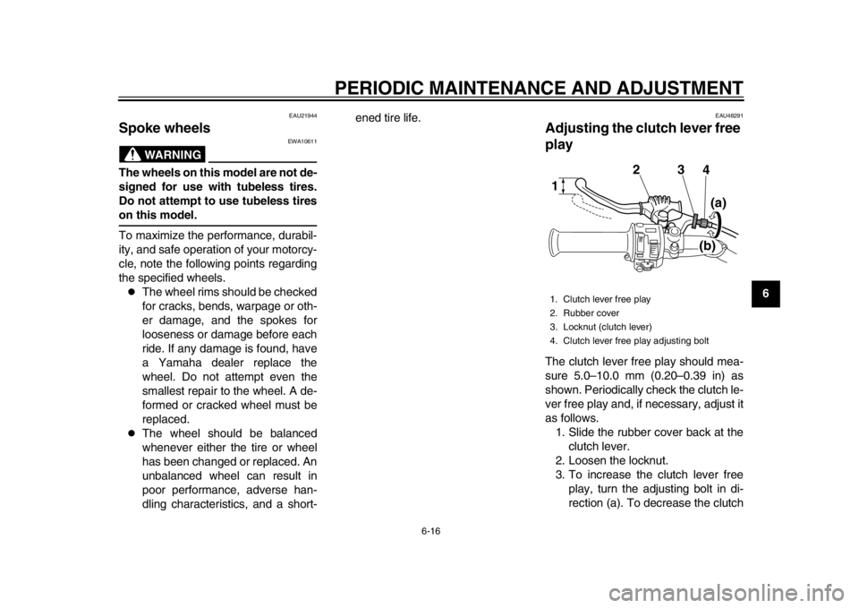
playThe clutch lever free play should mea-
sure 5.0–10.0 mm (0.20–0.39 in) as
shown. Periodically check the clutch le-
ver free play and, if necessary, adjust it
as follows.
1. Slide the rubber cover back at the clutch lever.
2. Loosen the locknut.
3. To increase the clutch lever free play, turn the adjusting bolt in di-
rection (a). To decrease the clutch1. Clutch lever free play
2. Rubber cover
3. Locknut (clutch lever)
4. Clutch lever free play adjusting bolt
32
4(a)
(b)
1
2RD-9-E0.book 16 ページ 2013年11月28日 木曜日 午後4時18分