YAMAHA SUPERJET 2001 Owner's Manual
Manufacturer: YAMAHA, Model Year: 2001, Model line: SUPERJET, Model: YAMAHA SUPERJET 2001Pages: 107, PDF Size: 6.2 MB
Page 21 of 107
1-14
E
EJU00319
Safe boating rules
Your Yamaha watercraft is legally consid-
ered a powerboat. Operation of the water-
craft must be in accordance with the rules
and regulations governing the waterway on
which it is used.
EJU00322
Enjoy your watercraft
responsibly
You share the areas you enjoy when
riding your watercraft with others and with
nature. So your enjoyment includes a
responsibility to treat these other people,
and the lands, waters, and wildlife with
respect and courtesy.
Whenever and wherever you ride, think of
yourself as the guest of those around you.
Remember, for example, that the sound of
your watercraft may be music to you, but it
could be just noise to others. And the excit-
ing splash of your wake can make waves
others won’t enjoy. Avoid riding close to
shoreline homes and waterfowl nesting
areas or other wildlife areas, and keep a
respectful distance from fishermen, other
boats, swimmers, and populated beaches.
When travel in areas like these is unavoid-
able, ride slowly and obey all laws.
Remember that pollution can be harmful
to the environment. Do not refuel or add oil
where a spill could cause damage to nature.
Remove your watercraft from the water and
move it away from the shoreline before refu-
eling. And keep your surroundings pleasant
for the people and wildlife that share the
waterways: don’t litter!
When you ride responsibly, with respect
and courtesy for others, you help ensure
that our waterways stay open for the enjoy-
ment of a variety of recreational opportuni-
ties.
E_GM6-1.fm Page 14 Tuesday, July 11, 2000 10:49 AM
Page 22 of 107
E
–MEMO–
E_GM6-1.fm Page 15 Tuesday, July 11, 2000 10:49 AM
Page 23 of 107
E
2
EJU00326
FEATURES AND
FUNCTIONS
Location of main components............... 2-1
Operation of controls and other
functions ................................................... 2-3
Hood ........................................................ 2-3
Fuel tank filler cap ................................... 2-4
Fuel cock knob........................................ 2-4
Engine stop switch .................................. 2-5
Engine shut-off switch............................. 2-5
Choke knob ............................................. 2-6
Throttle lever ........................................... 2-6
Start switch.............................................. 2-6
Cooling water pilot outlet ........................ 2-7
Steering system ...................................... 2-7
Steering pole ........................................... 2-8
Engine overheat warning system ........... 2-9
Storage pouch....................................... 2-10
E_GM6-2TOC.fm Page 1 Tuesday, July 11, 2000 10:50 AM
Page 24 of 107
2-1
E
EJU00327
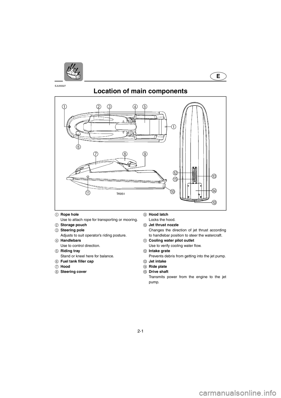
Location of main components
1Rope hole
Use to attach rope for transporting or mooring.
2Storage pouch
3Steering pole
Adjusts to suit operator’s riding posture.
4Handlebars
Use to control direction.
5Riding tray
Stand or kneel here for balance.
6Fuel tank filler cap
7Hood
8Steering cover9Hood latch
Locks the hood.
0Jet thrust nozzle
Changes the direction of jet thrust according
to handlebar position to steer the watercraft.
ACooling water pilot outlet
Use to verify cooling water flow.
BIntake grate
Prevents debris from getting into the jet pump.
CJet intake
DRide plate
EDrive shaft
Transmits power from the engine to the jet
pump.
E_GM6-2.fm Page 1 Tuesday, July 11, 2000 10:51 AM
Page 25 of 107
2-2
E
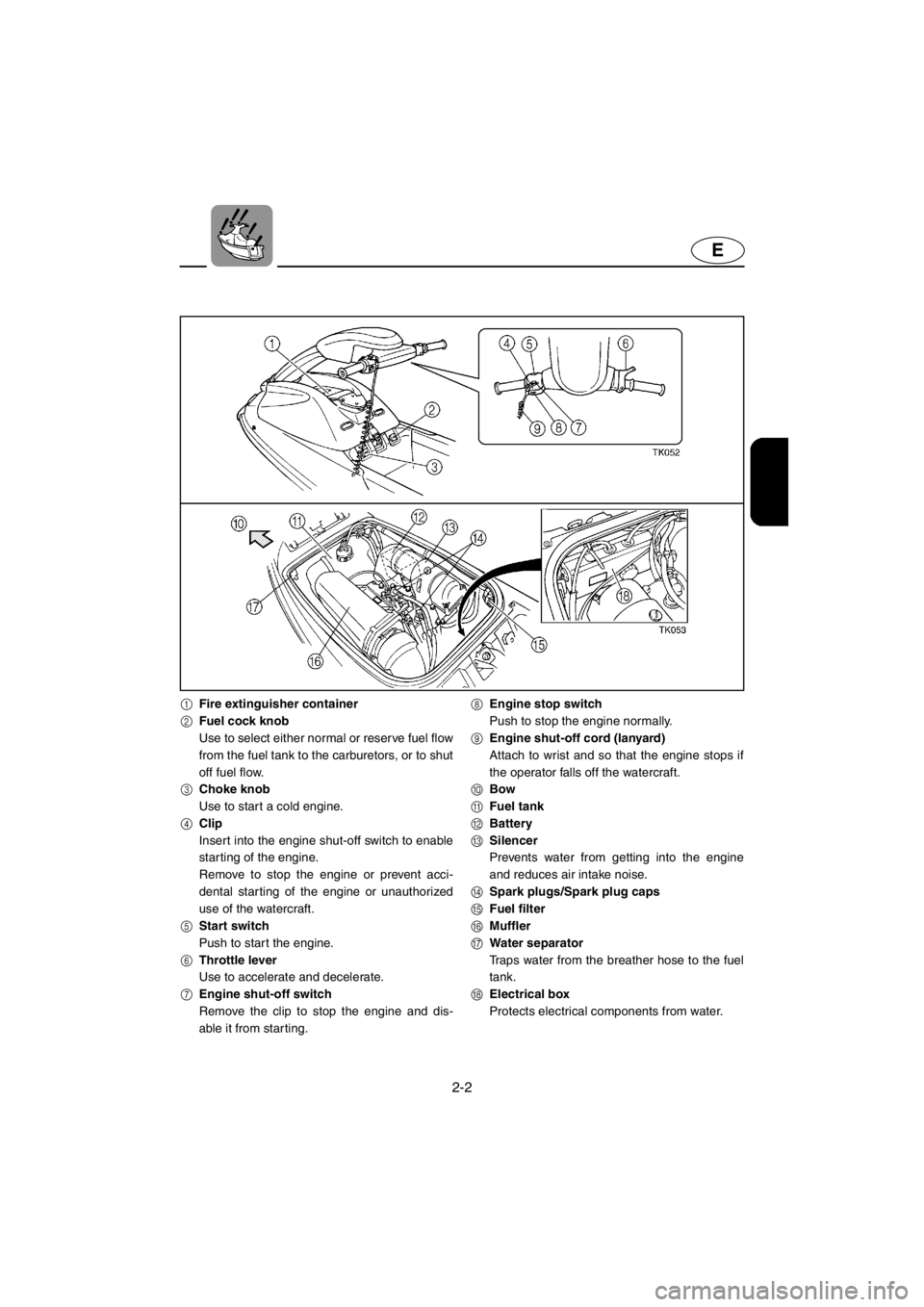
1Fire extinguisher container
2Fuel cock knob
Use to select either normal or reserve fuel flow
from the fuel tank to the carburetors, or to shut
off fuel flow.
3Choke knob
Use to start a cold engine.
4Clip
Insert into the engine shut-off switch to enable
starting of the engine.
Remove to stop the engine or prevent acci-
dental star ting of the engine or unauthorized
use of the watercraft.
5Start switch
Push to start the engine.
6Throttle lever
Use to accelerate and decelerate.
7Engine shut-off switch
Remove the clip to stop the engine and dis-
able it from starting.8Engine stop switch
Push to stop the engine normally.
9Engine shut-off cord (lanyard)
Attach to wrist and so that the engine stops if
the operator falls off the watercraft.
0Bow
AFuel tank
BBattery
CSilencer
Prevents water from getting into the engine
and reduces air intake noise.
DSpark plugs/Spark plug caps
EFuel filter
FMuffler
GWater separator
Traps water from the breather hose to the fuel
tank.
HElectrical box
Protects electrical components from water.
E_GM6-2.fm Page 2 Tuesday, July 11, 2000 10:51 AM
Page 26 of 107
2-3
E
EJU00328
Operation of controls and
other functions
EJU00338
Hood
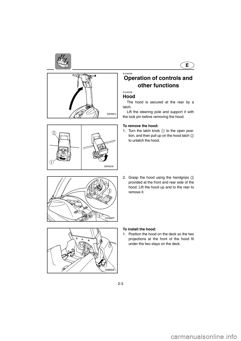
The hood is secured at the rear by a
latch.
Lift the steering pole and support it with
the lock pin before removing the hood.
To remove the hood:
1. Turn the latch knob 1 to the open posi-
tion, and then pull up on the hood latch 2
to unlatch the hood.
2. Grasp the hood using the handgrips 3
provided at the front and rear side of the
hood. Lift the hood up and to the rear to
remove it.
To install the hood:
1. Position the hood on the deck so the two
projections at the front of the hood fit
under the two stays on the deck.
E_GM6-2.fm Page 3 Tuesday, July 11, 2000 10:51 AM
Page 27 of 107
2-4
E
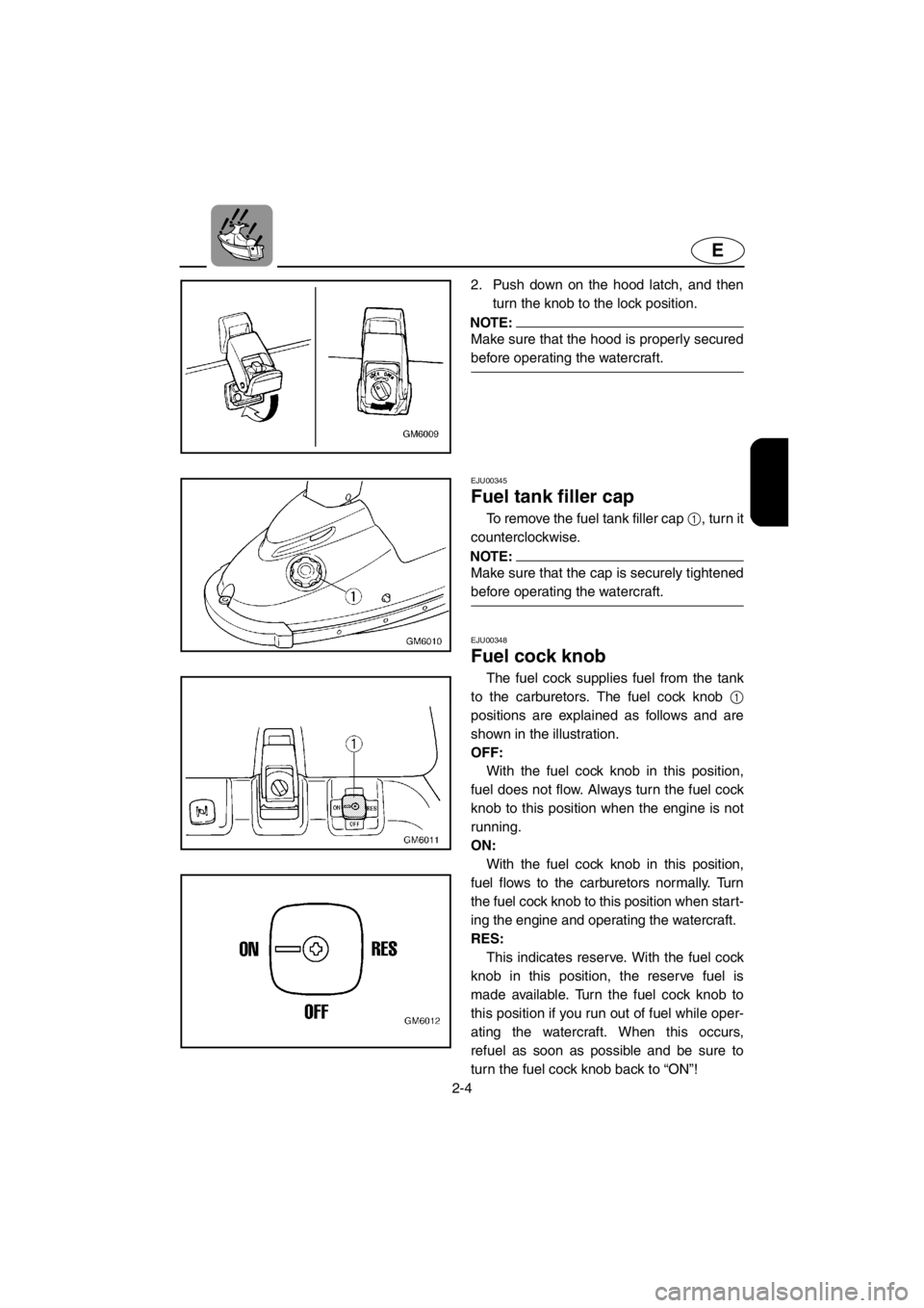
2. Push down on the hood latch, and then
turn the knob to the lock position.
NOTE:@Make sure that the hood is properly secured
before operating the watercraft.
@
EJU00345
Fuel tank filler cap
To remove the fuel tank filler cap 1, turn it
counterclockwise.
NOTE:@Make sure that the cap is securely tightened
before operating the watercraft.
@
EJU00348
Fuel cock knob
The fuel cock supplies fuel from the tank
to the carburetors. The fuel cock knob 1
positions are explained as follows and are
shown in the illustration.
OFF:
With the fuel cock knob in this position,
fuel does not flow. Always turn the fuel cock
knob to this position when the engine is not
running.
ON:
With the fuel cock knob in this position,
fuel flows to the carburetors normally. Turn
the fuel cock knob to this position when start-
ing the engine and operating the watercraft.
RES:
This indicates reserve. With the fuel cock
knob in this position, the reserve fuel is
made available. Tur n the fuel cock knob to
this position if you run out of fuel while oper-
ating the watercraft. When this occurs,
refuel as soon as possible and be sure to
turn the fuel cock knob back to “ON”!
E_GM6-2.fm Page 4 Tuesday, July 11, 2000 10:51 AM
Page 28 of 107
2-5
E
EJU00705
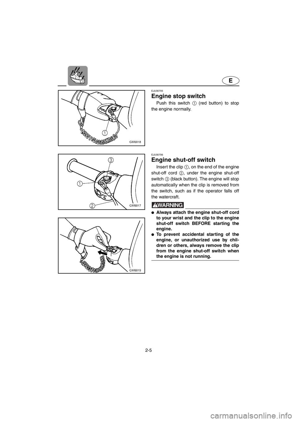
Engine stop switch
Push this switch 1 (red button) to stop
the engine normally.
EJU00706
Engine shut-off switch
Insert the clip 1, on the end of the engine
shut-off cord 2, under the engine shut-off
switch 3 (black button). The engine will stop
automatically when the clip is removed from
the switch, such as if the operator falls off
the watercraft.
WARNING@●Always attach the engine shut-off cord
to your wrist and the clip to the engine
shut-off switch BEFORE starting the
engine.
●To prevent accidental starting of the
engine, or unauthorized use by chil-
dren or others, always remove the clip
from the engine shut-off switch when
the engine is not running.
@
E_GM6-2.fm Page 5 Tuesday, July 11, 2000 10:51 AM
Page 29 of 107
2-6
E
EJU00350
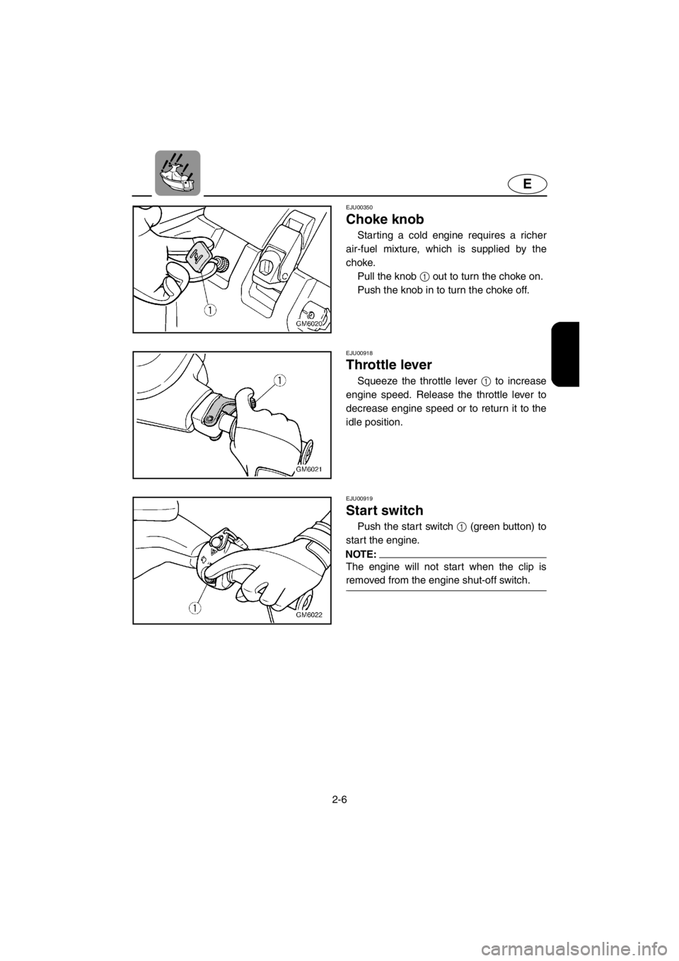
Choke knob
Starting a cold engine requires a richer
air-fuel mixture, which is supplied by the
choke.
Pull the knob 1 out to turn the choke on.
Push the knob in to turn the choke off.
EJU00918
Throttle lever
Squeeze the throttle lever 1 to increase
engine speed. Release the throttle lever to
decrease engine speed or to return it to the
idle position.
EJU00919
Start switch
Push the start switch 1 (green button) to
start the engine.
NOTE:@The engine will not start when the clip is
removed from the engine shut-off switch.
@
E_GM6-2.fm Page 6 Tuesday, July 11, 2000 10:51 AM
Page 30 of 107
2-7
E
EJU00923
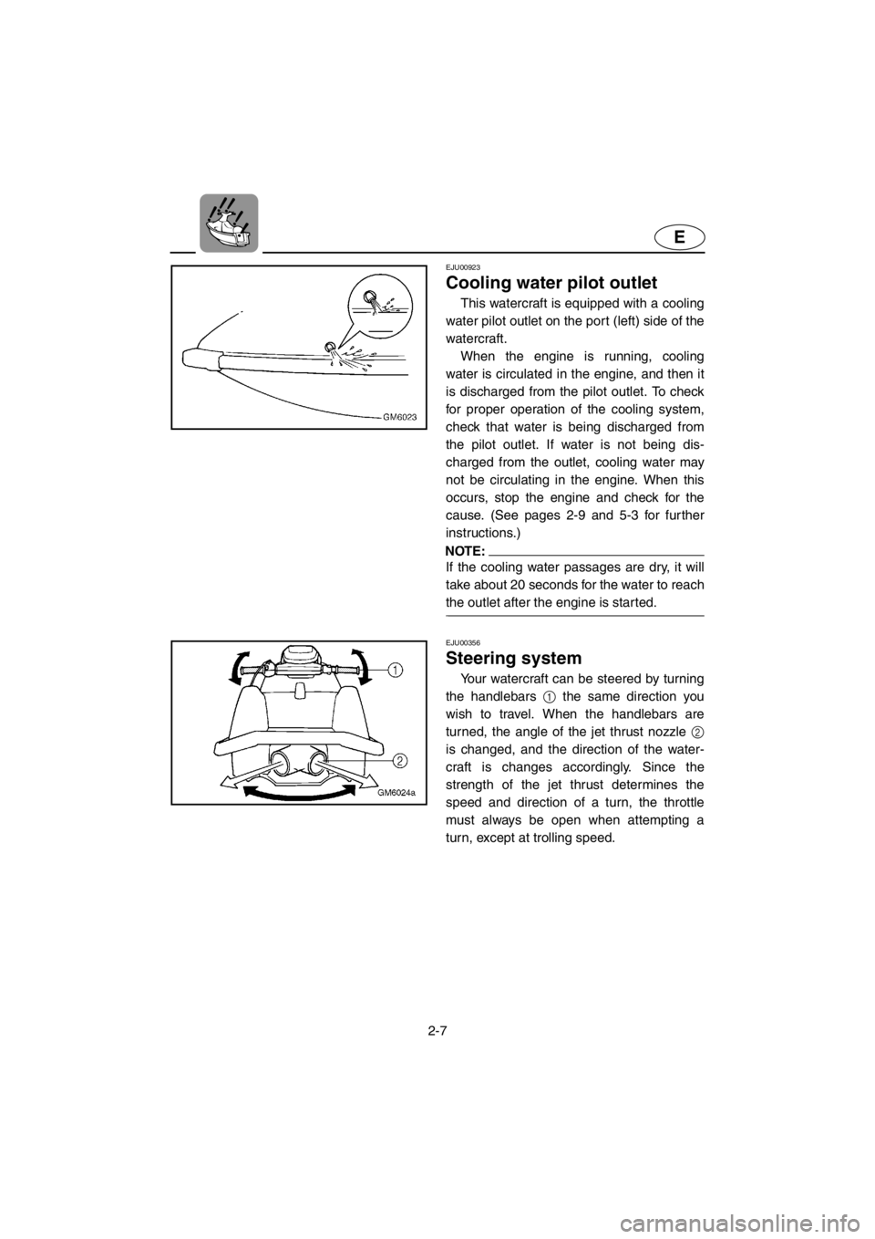
Cooling water pilot outlet
This watercraft is equipped with a cooling
water pilot outlet on the port (left) side of the
watercraft.
When the engine is running, cooling
water is circulated in the engine, and then it
is discharged from the pilot outlet. To check
for proper operation of the cooling system,
check that water is being discharged from
the pilot outlet. If water is not being dis-
charged from the outlet, cooling water may
not be circulating in the engine. When this
occurs, stop the engine and check for the
cause. (See pages 2-9 and 5-3 for further
instructions.)
NOTE:@If the cooling water passages are dry, it will
take about 20 seconds for the water to reach
the outlet after the engine is started.
@
EJU00356
Steering system
Your watercraft can be steered by turning
the handlebars 1 the same direction you
wish to travel. When the handlebars are
turned, the angle of the jet thrust nozzle 2
is changed, and the direction of the water-
craft is changes accordingly. Since the
strength of the jet thrust determines the
speed and direction of a turn, the throttle
must always be open when attempting a
turn, except at trolling speed.
E_GM6-2.fm Page 7 Tuesday, July 11, 2000 10:51 AM