transmission YAMAHA TDM 850 2001 Owners Manual
[x] Cancel search | Manufacturer: YAMAHA, Model Year: 2001, Model line: TDM 850, Model: YAMAHA TDM 850 2001Pages: 110, PDF Size: 12.15 MB
Page 17 of 110
INSTRUMENT AND CONTROL FUNCTIONS
3-2
3
EAU01590
(Parking)
The steering is locked, and the taillight
and auxiliary light are on, but all other
electrical systems are off. The key can
be removed.
The steering must be locked before the
key can be turned to “ ”.
ECA00043
CAUTION:_ Do not use the parking position for
an extended length of time, other-
wise the battery may discharge. _
EAU03034
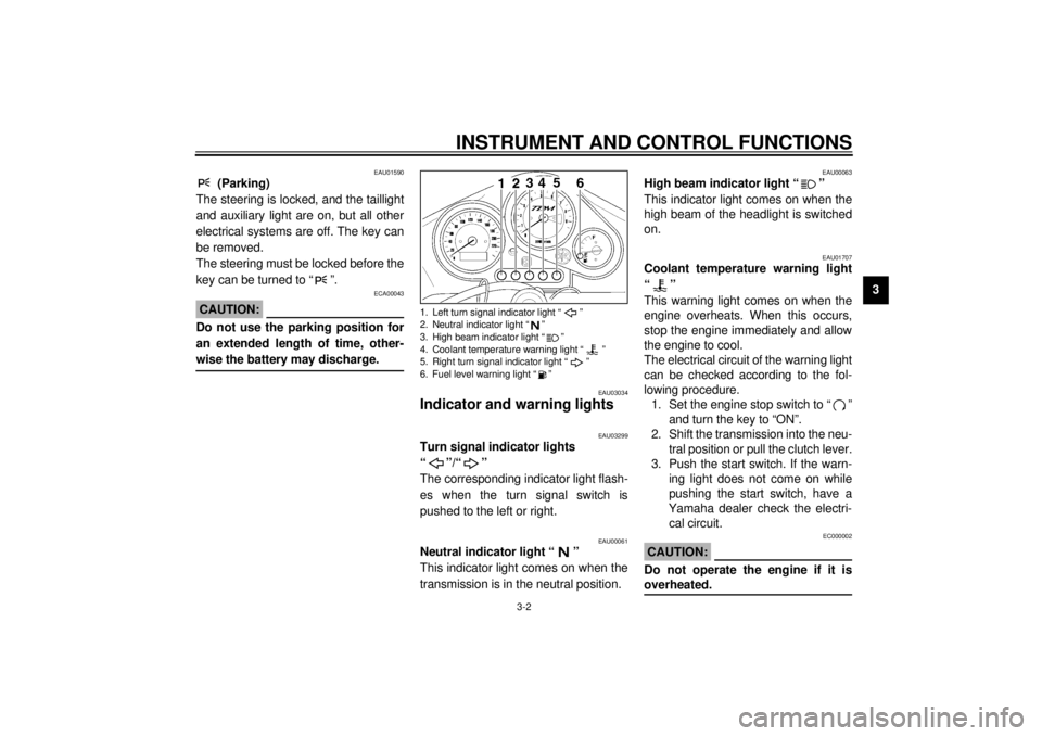
Indicator and warning lights
EAU03299
Turn signal indicator lights
“”/“”
The corresponding indicator light flash-
es when the turn signal switch is
pushed to the left or right.
EAU00061
Neutral indicator light “ ”
This indicator light comes on when the
transmission is in the neutral position.
EAU00063
High beam indicator light “ ”
This indicator light comes on when the
high beam of the headlight is switched
on.
EAU01707
Coolant temperature warning light
“”
This warning light comes on when the
engine overheats. When this occurs,
stop the engine immediately and allow
the engine to cool.
The electrical circuit of the warning light
can be checked according to the fol-
lowing procedure.
1. Set the engine stop switch to “ ”
and turn the key to “ON”.
2. Shift the transmission into the neu-
tral position or pull the clutch lever.
3. Push the start switch. If the warn-
ing light does not come on while
pushing the start switch, have a
Yamaha dealer check the electri-
cal circuit.
EC000002
CAUTION:@ Do not operate the engine if it is
overheated. @
1. Left turn signal indicator light “ ”
2. Neutral indicator light “ ”
3. High beam indicator light “ ”
4. Coolant temperature warning light “ ”
5. Right turn signal indicator light “ ”
6. Fuel level warning light “ ”
E_4tx.book Page 2 Wednesday, October 4, 2000 4:28 PM
Page 18 of 110
INSTRUMENT AND CONTROL FUNCTIONS
3-3
3
EAU03680
Fuel level warning light “ ”
This warning light comes on when the
fuel level drops below approximately
3.1 L. When this occurs, refuel as soon
as possible.
The electrical circuit of the warning light
can be checked according to the fol-
lowing procedure.
1. Set the engine stop switch to “ ”
and turn the key to “ON”.
2. Shift the transmission into the neu-
tral position or pull the clutch lever.
3. Push the start switch. If the warn-
ing light does not come on, have a
Yamaha dealer check the electri-
cal circuit.
EAU03492
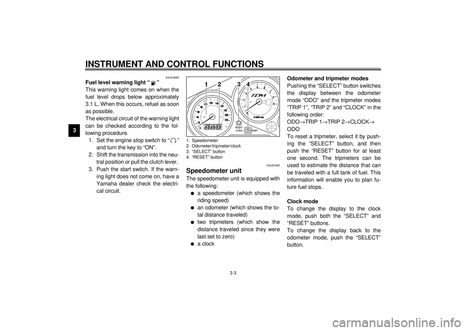
Speedometer unit The speedometer unit is equipped with
the following:l
a speedometer (which shows the
riding speed)
l
an odometer (which shows the to-
tal distance traveled)
l
two tripmeters (which show the
distance traveled since they were
last set to zero)
l
a clockOdometer and tripmeter modes
Pushing the “SELECT” button switches
the display between the odometer
mode “ODO” and the tripmeter modes
“TRIP 1”, “TRIP 2” and “CLOCK” in the
following order:
ODO
®TRIP 1
®TRIP 2
®CLOCK
®
ODO
To reset a tripmeter, select it by push-
ing the “SELECT” button, and then
push the “RESET” button for at least
one second. The tripmeters can be
used to estimate the distance that can
be traveled with a full tank of fuel. This
information will enable you to plan fu-
ture fuel stops.
Clock mode
To change the display to the clock
mode, push both the “SELECT” and
“RESET” buttons.
To change the display back to the
odometer mode, push the “SELECT”
button.
1. Speedometer
2. Odometer/tripmeter/clock
3. “SELECT” button
4. “RESET” button
E_4tx.book Page 3 Wednesday, October 4, 2000 4:28 PM
Page 22 of 110
INSTRUMENT AND CONTROL FUNCTIONS
3-7
3
EAU00152
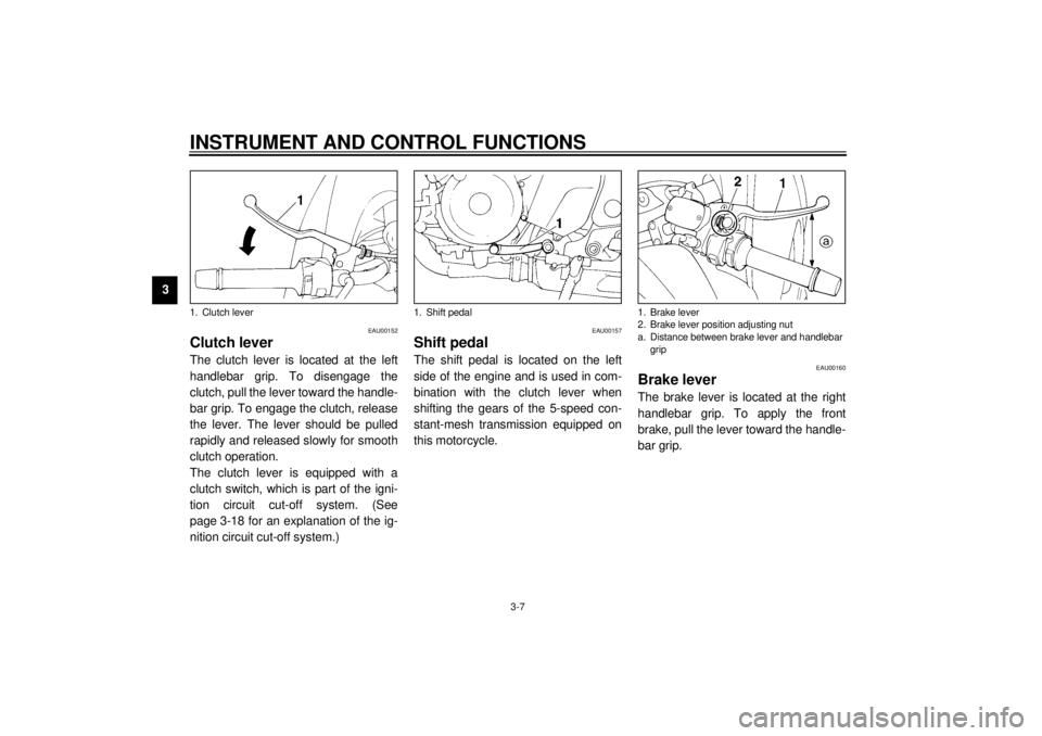
Clutch lever The clutch lever is located at the left
handlebar grip. To disengage the
clutch, pull the lever toward the handle-
bar grip. To engage the clutch, release
the lever. The lever should be pulled
rapidly and released slowly for smooth
clutch operation.
The clutch lever is equipped with a
clutch switch, which is part of the igni-
tion circuit cut-off system. (See
page 3-18 for an explanation of the ig-
nition circuit cut-off system.)
EAU00157
Shift pedal The shift pedal is located on the left
side of the engine and is used in com-
bination with the clutch lever when
shifting the gears of the 5-speed con-
stant-mesh transmission equipped on
this motorcycle.
EAU00160
Brake lever The brake lever is located at the right
handlebar grip. To apply the front
brake, pull the lever toward the handle-
bar grip.
1. Clutch lever
1. Shift pedal
1. Brake lever
2. Brake lever position adjusting nut
a. Distance between brake lever and handlebar
grip
E_4tx.book Page 7 Wednesday, October 4, 2000 4:28 PM
Page 33 of 110
INSTRUMENT AND CONTROL FUNCTIONS
3-18
3
EW000044
WARNING
@ The motorcycle must not be ridden
with the sidestand down, or if the
sidestand cannot be properly
moved up (or does not stay up), oth-
erwise the sidestand could contact
the ground and distract the opera-
tor, resulting in a possible loss of
control. Yamaha’s ignition circuit
cut-off system has been designed to
assist the operator in fulfilling the
responsibility of raising the side-
stand before starting off. Therefore,
check this system regularly as de-
scribed below and have a Yamaha
dealer repair it if it does not function
properly. @
EAU03720
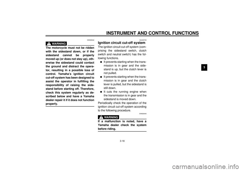
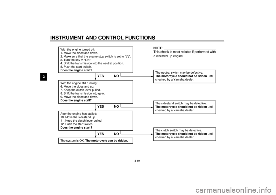
Ignition circuit cut-off system The ignition circuit cut-off system (com-
prising the sidestand switch, clutch
switch and neutral switch) has the fol-
lowing functions.l
It prevents starting when the trans-
mission is in gear and the side-
stand is up, but the clutch lever is
not pulled.
l
It prevents starting when the trans-
mission is in gear and the clutch
lever is pulled, but the sidestand is
still down.
l
It cuts the running engine when
the transmission is in gear and the
sidestand is moved down.
Periodically check the operation of the
ignition circuit cut-off system according
to the following procedure.
EW000045
WARNING
_ If a malfunction is noted, have a
Yamaha dealer check the system
before riding. _
E_4tx.book Page 18 Wednesday, October 4, 2000 4:28 PM
Page 34 of 110
INSTRUMENT AND CONTROL FUNCTIONS
3-19
3
CD-01E
With the engine turned off:
1. Move the sidestand down.
2. Make sure that the engine stop switch is set to “ ”.
3. Turn the key to “ON”.
4. Shift the transmission into the neutral position.
5. Push the start switch.
Does the engine start?
The neutral switch may be defective.
The motorcycle should not be ridden until
checked by a Yamaha dealer.
With the engine still running:
6. Move the sidestand up.
7. Keep the clutch lever pulled.
8. Shift the transmission into gear.
9. Move the sidestand down.
Does the engine stall?After the engine has stalled:
10. Move the sidestand up.
11. Keep the clutch lever pulled.
12. Push the start switch.
Does the engine start?
The sidestand switch may be defective.
The motorcycle should not be ridden until
checked by a Yamaha dealer.The clutch switch may be defective.
The motorcycle should not be ridden until
checked by a Yamaha dealer.
NO
NOTE:This check is most reliable if performed with
a warmed-up engine.
YESYES NO
The system is OK.
The motorcycle can be ridden.
YES NO
E_4tx.book Page 19 Wednesday, October 4, 2000 4:28 PM
Page 40 of 110
5-1
5
EAU00372
5-OPERATION AND IMPORTANT RIDING POINTS
EAU00373
WARNING
@ l
Become thoroughly familiar
with all operating controls and
their functions before riding.
Consult a Yamaha dealer re-
garding any control or function
that you do not thoroughly un-
derstand.
l
Never start the engine or oper-
ate it in a closed area for any
length of time. Exhaust fumes
are poisonous, and inhaling
them can cause loss of con-
sciousness and death within a
short time. Always make sure
that there is adequate ventila-
tion.
l
Before starting out, make sure
that the sidestand is up. If the
sidestand is not raised com-
pletely, it could contact the
ground and distract the opera-
tor, resulting in a possible loss
of control.
@
EAU03827*
Starting the engine In order for the ignition circuit cut-off
system to enable starting, one of the
following conditions must be met:l
The transmission is in the neutral
position.
l
The transmission is in gear with
the clutch lever pulled and the
sidestand up.
EW000054
WARNING
_ l
Before starting the engine,
check the function of the igni-
tion circuit cut-off system ac-
cording to the procedure
described on page 3-19.
l
Never ride with the sidestand
down.
_1. Turn the key to “ON” and make
sure that the engine stop switch is
set to “ ”.
EC000035
CAUTION:_ If the fuel level warning light comes
on, check the fuel level, and, if nec-
essary, refuel as soon as possible. _2. Shift the transmission into the neu-
tral position.NOTE:_ When the transmission is in the neutral
position, the neutral indicator light
should be on, otherwise have a
Yamaha dealer check the electrical cir-
cuit. _3. Turn the starter (choke) on and
completely close the throttle. (See
page 3-10 for starter (choke) oper-
ation.)
4. Start the engine by pushing the
start switch.
E_4tx.book Page 1 Wednesday, October 4, 2000 4:28 PM
Page 42 of 110

OPERATION AND IMPORTANT RIDING POINTS
5-3
5
EAU00423
Shifting Shifting gears lets you control the
amount of engine power available for
starting off, accelerating, climbing hills,
etc.
The gear positions are shown in the il-
lustration.NOTE:@ To shift the transmission into the neu-
tral position, press the shift pedal down
repeatedly until it reaches the end of its
travel, and then slightly raise it. @
EC000048
CAUTION:@ l
Even with the transmission in
the neutral position, do not
coast for long periods of time
with the engine off, and do not
tow the motorcycle for long dis-
tances. The transmission is
properly lubricated only when
the engine is running. Inade-
quate lubrication may damage
the transmission.
l
Always use the clutch while
changing gears to avoid dam-
aging the engine, transmission,
and drive train, which are not
designed to withstand the
shock of forced shifting.
@
EAU02941
Recommended shift points
(for Switzerland only) The recommended shift points during
acceleration are shown in the table be-
low.CF-01ENOTE:_ When shifting down two gears at a
time, reduce the speed accordingly
(e.g., down to 35 km/h when shifting
from 4th to 2nd gear). _
1. Shift pedal
N. Neutral position
Shift point
(km/h)
1st®2nd
2nd®3rd
3rd®4th
4th®5th23
36
50
60
E_4tx.book Page 3 Wednesday, October 4, 2000 4:28 PM
Page 72 of 110
PERIODIC MAINTENANCE AND MINOR REPAIR
6-27
6
EAU00744
Drive chain slack The drive chain slack should be
checked before each ride and adjusted
if necessary.
To check the drive chain slack
1. Place the motorcycle on a level
surface and hold it in an upright
position.NOTE:@ When checking and adjusting the drive
chain slack, the motorcycle should be
positioned straight up and there should
be no weight on it. @
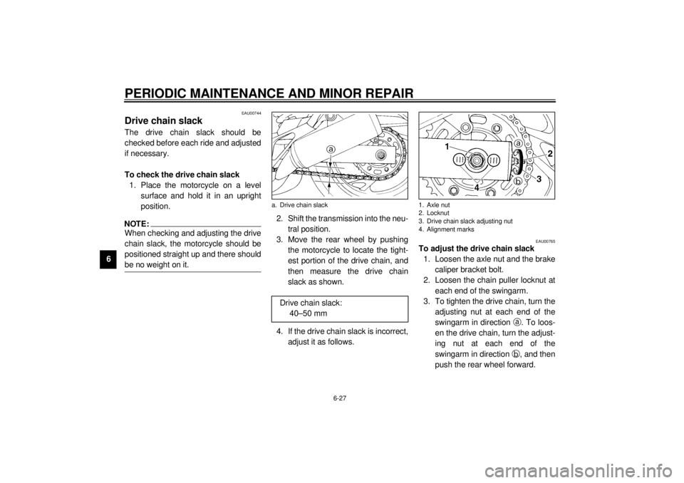
2. Shift the transmission into the neu-
tral position.
3. Move the rear wheel by pushing
the motorcycle to locate the tight-
est portion of the drive chain, and
then measure the drive chain
slack as shown.
4. If the drive chain slack is incorrect,
adjust it as follows.
EAU00765
To adjust the drive chain slack
1. Loosen the axle nut and the brake
caliper bracket bolt.
2. Loosen the chain puller locknut at
each end of the swingarm.
3. To tighten the drive chain, turn the
adjusting nut at each end of the
swingarm in direction
a. To loos-
en the drive chain, turn the adjust-
ing nut at each end of the
swingarm in direction
b, and then
push the rear wheel forward.
a. Drive chain slack
Drive chain slack:
40–50 mm
1. Axle nut
2. Locknut
3. Drive chain slack adjusting nut
4. Alignment marks
E_4tx.book Page 27 Wednesday, October 4, 2000 4:28 PM
Page 99 of 110

SPECIFICATIONS
8-2
8
Cooling system capacity
(total amount)
1.7 L
Air filterDry type element
Fuel
Type Regular unleaded gasoline
Fuel tank capacity 20 L
Fuel reserve amount 3.1 L
Carburetor
Manufacturer MIKUNI
Model ´ quantity BDSR38 ´ 2
Spark plug
Manufacturer/model NGK / DPR8EA-9 or
DENSO / X24EPR-U9
Gap 0.8–0.9 mm
Clutch typeWet, multiple-disc
Transmission
Primary reduction system Spur gear
Primary reduction ratio 1.718
Secondary reduction system Chain drive
Secondary reduction ratio 2.688
Number of drive chain
sprocket teeth (front/rear) 16/43
Transmission type Constant-mesh 5-speedOperation Left foot
Gear ratio
1st 2.643
2nd 1.947
3rd 1.500
4th 1.174
5th 0.964
Chassis
Frame type Diamond
Caster angle 24.5°
Trail 103 mm
Tires
Front
Type Tubeless tire
Size 110/80 ZR18 (58W)
Manufacturer/model Bridgestone / BT54F
Pirelli / MTR03
Michelin / MACADAM90X
Rear
Type Tubeless tire
Size 150/70 ZR17 (69W)
Manufacturer/model Bridgestone / BT54R
Pirelli / MTR04
Michelin / MACADAM90X
E_4tx.book Page 2 Wednesday, October 4, 2000 4:28 PM