air filter YAMAHA TDM 900 2003 Owners Manual
[x] Cancel search | Manufacturer: YAMAHA, Model Year: 2003, Model line: TDM 900, Model: YAMAHA TDM 900 2003Pages: 110, PDF Size: 7.38 MB
Page 11 of 110
2-1
EAU00026
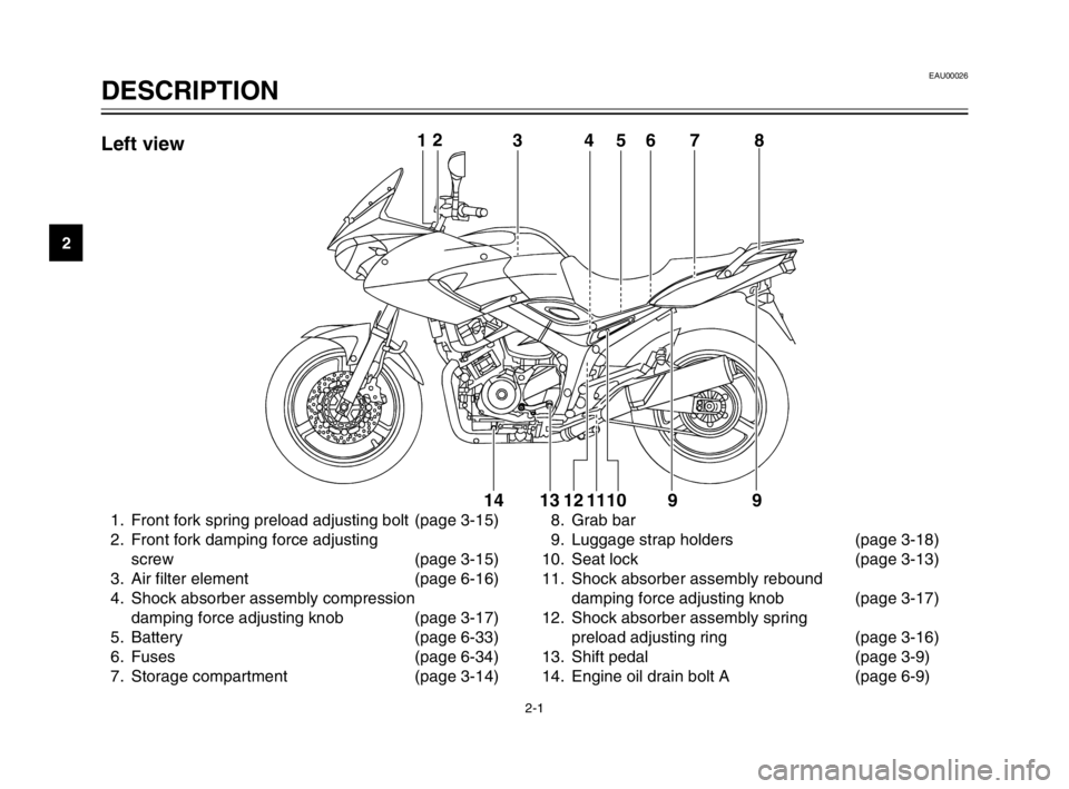
DESCRIPTIONPart locations
2
1. Front fork spring preload adjusting bolt (page 3-15)
2. Front fork damping force adjusting
screw (page 3-15)
3. Air filter element (page 6-16)
4. Shock absorber assembly compression
damping force adjusting knob (page 3-17)
5. Battery (page 6-33)
6. Fuses (page 6-34)
7. Storage compartment (page 3-14)8. Grab bar
9. Luggage strap holders (page 3-18)
10. Seat lock (page 3-13)
11. Shock absorber assembly rebound
damping force adjusting knob (page 3-17)
12. Shock absorber assembly spring
preload adjusting ring (page 3-16)
13. Shift pedal (page 3-9)
14. Engine oil drain bolt A (page 6-9)
12
345678
9 9 10 11 12 13 1412
345678
9 9 10 11 12 13 14Left view
5PS-28199-E1 8/29/02 9:16 AM Page 10
Page 46 of 110
PERIODIC MAINTENANCE AND MINOR REPAIR
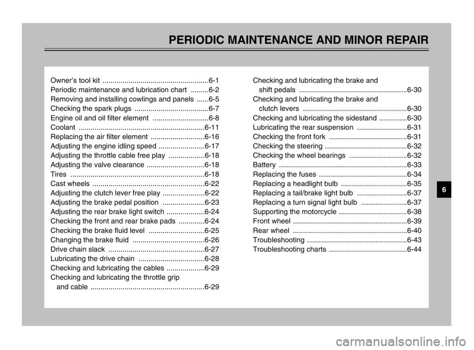
Owner’s tool kit .....................................................6-1
Periodic maintenance and lubrication chart .........6-2
Removing and installing cowlings and panels ......6-5
Checking the spark plugs .....................................6-7
Engine oil and oil filter element ............................6-8
Coolant ...............................................................6-11
Replacing the air filter element ...........................6-16
Adjusting the engine idling speed .......................6-17
Adjusting the throttle cable free play ..................6-18
Adjusting the valve clearance .............................6-18
Tires ...................................................................6-18
Cast wheels ........................................................6-22
Adjusting the clutch lever free play .....................6-22
Adjusting the brake pedal position .....................6-23
Adjusting the rear brake light switch ...................6-24
Checking the front and rear brake pads .............6-24
Checking the brake fluid level ............................6-25
Changing the brake fluid ....................................6-26
Drive chain slack ................................................6-27
Lubricating the drive chain .................................6-28
Checking and lubricating the cables ...................6-29
Checking and lubricating the throttle grip
and cable .........................................................6-29Checking and lubricating the brake and
shift pedals ......................................................6-30
Checking and lubricating the brake and
clutch levers ....................................................6-30
Checking and lubricating the sidestand ..............6-30
Lubricating the rear suspension .........................6-31
Checking the front fork .......................................6-31
Checking the steering .........................................6-32
Checking the wheel bearings .............................6-32
Battery ................................................................6-33
Replacing the fuses ............................................6-34
Replacing a headlight bulb .................................6-35
Replacing a tail/brake light bulb .........................6-37
Replacing a turn signal light bulb .......................6-37
Supporting the motorcycle ..................................6-38
Front wheel .........................................................6-39
Rear wheel .........................................................6-40
Troubleshooting ..................................................6-43
Troubleshooting charts .......................................6-44
6
5PS-28199-E1 8/29/02 9:16 AM Page 45
Page 48 of 110
6-2
PERIODIC MAINTENANCE AND MINOR REPAIR
6
EAU03685
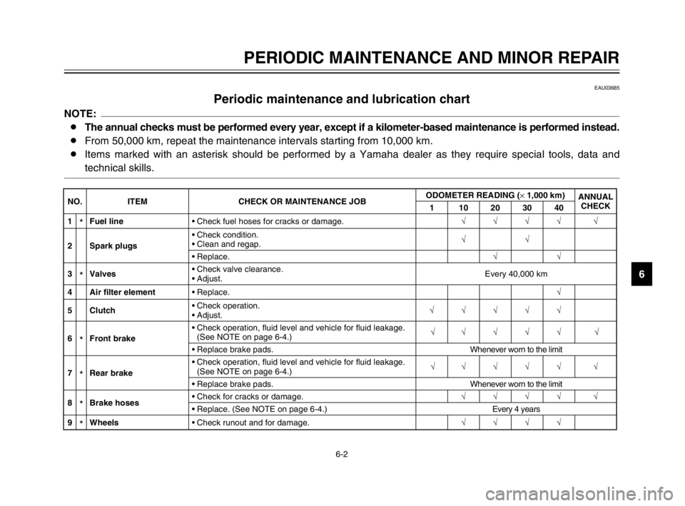
Periodic maintenance and lubrication chartPeriodic maintenance and lubrication chartNOTE:
8The annual checks must be performed every year, except if a kilometer-based maintenance is performed instead.
8From 50,000 km, repeat the maintenance intervals starting from 10,000 km.
8Items marked with an asterisk should be performed by a Yamaha dealer as they require special tools, data and
technical skills.
NO. ITEM CHECK OR MAINTENANCE JOBODOMETER READING (× 1,000 km)
ANNUAL
CHECK
1 10203040
1
*Fuel line•Check fuel hoses for cracks or damage.√√√√ √
2 Spark plugs•Check condition.
•Clean and regap.√√
•Replace.√√
3
*Valves•Check valve clearance.
•Adjust.Every 40,000 km
4 Air filter element•Replace.√
5 Clutch•Check operation.
•Adjust.√√√√√
6
*Front brake•Check operation, fluid level and vehicle for fluid leakage.
(See NOTE on page 6-4.)√√√√√ √
•Replace brake pads.Whenever worn to the limit
7
*Rear brake•Check operation, fluid level and vehicle for fluid leakage.
(See NOTE on page 6-4.)√√√√√ √
•Replace brake pads.Whenever worn to the limit
8
*Brake hoses•Check for cracks or damage.√√√√ √
•Replace. (See NOTE on page 6-4.)Every 4 years
9
*Wheels•Check runout and for damage.√√√√
5PS-28199-E1 8/29/02 9:16 AM Page 47
Page 50 of 110
6-4
PERIODIC MAINTENANCE AND MINOR REPAIR
6
EAU03884
NOTE:
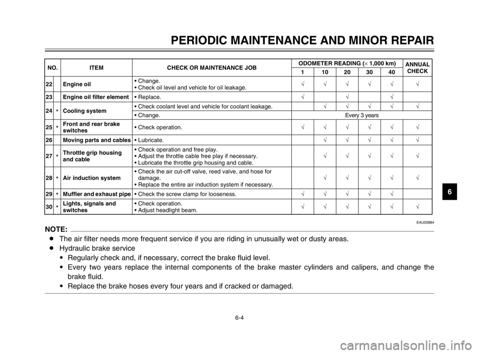
8The air filter needs more frequent service if you are riding in unusually wet or dusty areas.
8Hydraulic brake service
9Regularly check and, if necessary, correct the brake fluid level.
9Every two years replace the internal components of the brake master cylinders and calipers, and change the
brake fluid.
9Replace the brake hoses every four years and if cracked or damaged.
22 Engine oil•Change.
•Check oil level and vehicle for oil leakage.√√√√√ √
23 Engine oil filter element•Replace.√√√
24
*Cooling system•Check coolant level and vehicle for coolant leakage.√√√√ √
•Change.Every 3 years
25
*Front and rear brake
switches•Check operation.√√√√√ √
26 Moving parts and cables•Lubricate.√√√√ √
27
*Throttle grip housing
and cable•Check operation and free play.
•Adjust the throttle cable free play if necessary.
•Lubricate the throttle grip housing and cable.√√√√ √
28
*Air induction system•Check the air cut-off valve, reed valve, and hose for
damage.
•Replace the entire air induction system if necessary.√√√√ √
29
*Muffler and exhaust pipe•Check the screw clamp for looseness.√√√√√
30
*Lights, signals and
switches•Check operation.
•Adjust headlight beam.√√√√√ √ NO. ITEM CHECK OR MAINTENANCE JOBODOMETER READING (× 1,000 km)
ANNUAL
CHECK
1 10203040
5PS-28199-E1 8/29/02 9:16 AM Page 49
Page 54 of 110
6-8
PERIODIC MAINTENANCE AND MINOR REPAIR
6
NOTE:
If a torque wrench is not available
when installing a spark plug, a good
estimate of the correct torque is
1/4–1/2 turn past finger tight.
However, the spark plug should be
tightened to the specified torque as
soon as possible.
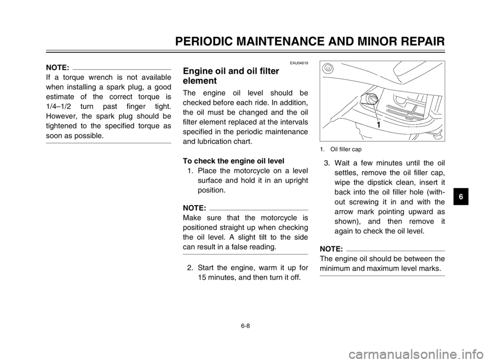
3. Wait a few minutes until the oil
settles, remove the oil filler cap,
wipe the dipstick clean, insert it
back into the oil filler hole (with-
out screwing it in and with the
arrow mark pointing upward as
shown), and then remove it
again to check the oil level.
NOTE:
The engine oil should be between the
minimum and maximum level marks.
1. Oil filler cap
EAU04619
Engine oil and oil filter
element
Engine oil and oil filter elementThe engine oil level should be
checked before each ride. In addition,
the oil must be changed and the oil
filter element replaced at the intervals
specified in the periodic maintenance
and lubrication chart.
To check the engine oil level
1. Place the motorcycle on a level
surface and hold it in an upright
position.
NOTE:
Make sure that the motorcycle is
positioned straight up when checking
the oil level. A slight tilt to the side
can result in a false reading.
2. Start the engine, warm it up for
15 minutes, and then turn it off.
5PS-28199-E1 8/29/02 9:16 AM Page 53
Page 55 of 110
6-9
PERIODIC MAINTENANCE AND MINOR REPAIR
6
EC000000
cC
Do not operate the motorcycle
until you know that the engine oil
level is sufficient.
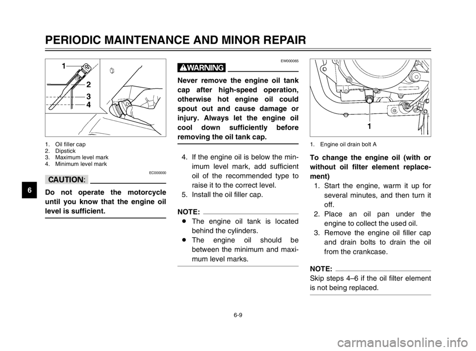
1. Oil filler cap
2. Dipstick
3. Maximum level mark
4. Minimum level mark
To change the engine oil (with or
without oil filter element replace-
ment)
1. Start the engine, warm it up for
several minutes, and then turn it
off.
2. Place an oil pan under the
engine to collect the used oil.
3. Remove the engine oil filler cap
and drain bolts to drain the oil
from the crankcase.
NOTE:
Skip steps 4–6 if the oil filter element
is not being replaced.
1. Engine oil drain bolt A
EW000065
w
Never remove the engine oil tank
cap after high-speed operation,
otherwise hot engine oil could
spout out and cause damage or
injury. Always let the engine oil
cool down sufficiently before
removing the oil tank cap.
4. If the engine oil is below the min-
imum level mark, add sufficient
oil of the recommended type to
raise it to the correct level.
5. Install the oil filler cap.
NOTE:
8The engine oil tank is located
behind the cylinders.
8The engine oil should be
between the minimum and maxi-
mum level marks.
5PS-28199-E1 8/29/02 9:16 AM Page 54
Page 56 of 110
6-10
PERIODIC MAINTENANCE AND MINOR REPAIR
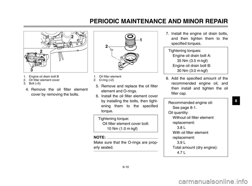
6 4. Remove the oil filter element
cover by removing the bolts.
1. Engine oil drain bolt B
2. Oil filter element cover
3. Bolt (×5)
7. Install the engine oil drain bolts,
and then tighten them to the
specified torques.
8. Add the specified amount of the
recommended engine oil, and
then install and tighten the oil
filler cap. 5. Remove and replace the oil filter
element and O-rings.
6. Install the oil filter element cover
by installing the bolts, then tight-
ening them to the specified
torque.
NOTE:
Make sure that the O-rings are prop-
erly seated.
1. Oil filter element
2. O-ring (×2)
Tightening torque:
Oil filter element cover bolt:
10 Nm (1.0 m·kgf)
Tightening torques:
Engine oil drain bolt A:
35 Nm (3.5 m·kgf)
Engine oil drain bolt B:
30 Nm (3.0 m·kgf)
Recommended engine oil:
See page 8-1.
Oil quantity:
Without oil filter element
replacement:
3.8 L
With oil filter element
replacement:
3.9 L
Total amount (dry engine):
4.7 L
5PS-28199-E1 8/29/02 9:16 AM Page 55
Page 62 of 110
6-16
PERIODIC MAINTENANCE AND MINOR REPAIR
6
EAU04973
Replacing the air filter
element
Air filter element, replacingThe air filter element should be
replaced at the intervals specified in
the periodic maintenance and lubrica-
tion chart. Replace the air filter ele-
ment more frequently if you are riding
in unusually wet or dusty areas.
1. Remove the seat. (See page
3-13 for seat removal and instal-
lation procedures.)
2. Remove cowlings A and B as
well as panels A and B. (See
pages 6-5 and 6-6 for cowling
and panel removal and installa-
tion procedures.)
1. Bolt (×2)
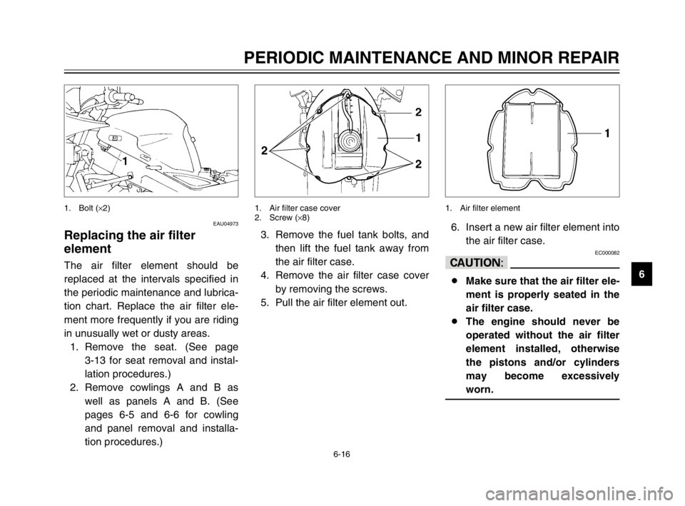
6. Insert a new air filter element into
the air filter case.
EC000082
cC
8Make sure that the air filter ele-
ment is properly seated in the
air filter case.
8The engine should never be
operated without the air filter
element installed, otherwise
the pistons and/or cylinders
may become excessively
worn.
1. Air filter element
3. Remove the fuel tank bolts, and
then lift the fuel tank away from
the air filter case.
4. Remove the air filter case cover
by removing the screws.
5. Pull the air filter element out.
1. Air filter case cover
2. Screw (×8)
5PS-28199-E1 8/29/02 9:16 AM Page 61
Page 63 of 110
6-17
PERIODIC MAINTENANCE AND MINOR REPAIR
67. Install the air filter case cover by
installing the screws.
8. Place the fuel tank in the original
position and install the bolts.
EWA00067
w
8Before installing the fuel tank,
make sure that the fuel hoses
are not damaged. If any fuel
hose is damaged, do not start
the engine but have a Yamaha
dealer replace the hose, other-
wise fuel may leak.
8Make sure that the fuel hoses
are properly connected and
routed, and not pinched.
8Be sure to place the fuel tank
breather hose and the fuel
tank overflow hose in the orig-
inal position.
9. Install the panels and cowlings.
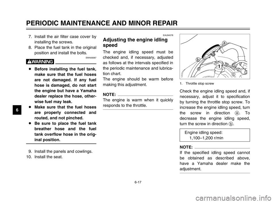
10. Install the seat.Check the engine idling speed and, if
necessary, adjust it to specification
by turning the throttle stop screw. To
increase the engine idling speed, turn
the screw in direction a. To
decrease the engine idling speed,
turn the screw in direction b.
NOTE:
If the specified idling speed cannot
be obtained as described above,
have a Yamaha dealer make the
adjustment.
1. Throttle stop screw
EAU04578
Adjusting the engine idling
speed
Engine idling speedThe engine idling speed must be
checked and, if necessary, adjusted
as follows at the intervals specified in
the periodic maintenance and lubrica-
tion chart.
The engine should be warm before
making this adjustment.
NOTE:
The engine is warm when it quickly
responds to the throttle.
Engine idling speed:
1,100–1,200 r/min
5PS-28199-E1 8/29/02 9:16 AM Page 62
Page 100 of 110
8
8-2
SPECIFICATIONS
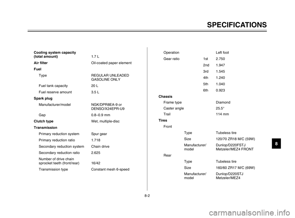
Cooling system capacity
(total amount)1.7 L
Air filterOil-coated paper element
Fuel
Type REGULAR UNLEADED
GASOLINE ONLY
Fuel tank capacity 20 L
Fuel reserve amount 3.5 L
Spark plug
Manufacturer/model NGK/DPR8EA-9 or
DENSO/X24EPR-U9
Gap 0.8–0.9 mm
Clutch typeWet, multiple-disc
Transmission
Primary reduction system Spur gear
Primary reduction ratio 1.718
Secondary reduction system Chain drive
Secondary reduction ratio 2.625
Number of drive chain
sprocket teeth (front/rear) 16/42
Transmission type Constant mesh 6-speedOperation Left foot
Gear ratio 1st 2.750
2nd 1.947
3rd 1.545
4th 1.240
5th 1.040
6th 0.923
Chassis
Frame type Diamond
Caster angle 25.5°
Trail 114 mm
Tires
Front
Type Tubeless tire
Size 120/70 ZR18 M/C (59W)
Manufacturer/ Dunlop/D220FSTJ
model Metzeler/MEZ4 FRONT
Rear
Type Tubeless tire
Size 160/60 ZR17 M/C (69W)
Manufacturer/ Dunlop/D220STJ
model Metzeler/MEZ4
5PS-28199-E1 8/29/02 9:17 AM Page 99