brake pads YAMAHA TDM 900 2003 Owners Manual
[x] Cancel search | Manufacturer: YAMAHA, Model Year: 2003, Model line: TDM 900, Model: YAMAHA TDM 900 2003Pages: 110, PDF Size: 7.38 MB
Page 46 of 110
PERIODIC MAINTENANCE AND MINOR REPAIR
Owner’s tool kit .....................................................6-1
Periodic maintenance and lubrication chart .........6-2
Removing and installing cowlings and panels ......6-5
Checking the spark plugs .....................................6-7
Engine oil and oil filter element ............................6-8
Coolant ...............................................................6-11
Replacing the air filter element ...........................6-16
Adjusting the engine idling speed .......................6-17
Adjusting the throttle cable free play ..................6-18
Adjusting the valve clearance .............................6-18
Tires ...................................................................6-18
Cast wheels ........................................................6-22
Adjusting the clutch lever free play .....................6-22
Adjusting the brake pedal position .....................6-23
Adjusting the rear brake light switch ...................6-24
Checking the front and rear brake pads .............6-24
Checking the brake fluid level ............................6-25
Changing the brake fluid ....................................6-26
Drive chain slack ................................................6-27
Lubricating the drive chain .................................6-28
Checking and lubricating the cables ...................6-29
Checking and lubricating the throttle grip
and cable .........................................................6-29Checking and lubricating the brake and
shift pedals ......................................................6-30
Checking and lubricating the brake and
clutch levers ....................................................6-30
Checking and lubricating the sidestand ..............6-30
Lubricating the rear suspension .........................6-31
Checking the front fork .......................................6-31
Checking the steering .........................................6-32
Checking the wheel bearings .............................6-32
Battery ................................................................6-33
Replacing the fuses ............................................6-34
Replacing a headlight bulb .................................6-35
Replacing a tail/brake light bulb .........................6-37
Replacing a turn signal light bulb .......................6-37
Supporting the motorcycle ..................................6-38
Front wheel .........................................................6-39
Rear wheel .........................................................6-40
Troubleshooting ..................................................6-43
Troubleshooting charts .......................................6-44
6
5PS-28199-E1 8/29/02 9:16 AM Page 45
Page 48 of 110

6-2
PERIODIC MAINTENANCE AND MINOR REPAIR
6
EAU03685
Periodic maintenance and lubrication chartPeriodic maintenance and lubrication chartNOTE:
8The annual checks must be performed every year, except if a kilometer-based maintenance is performed instead.
8From 50,000 km, repeat the maintenance intervals starting from 10,000 km.
8Items marked with an asterisk should be performed by a Yamaha dealer as they require special tools, data and
technical skills.
NO. ITEM CHECK OR MAINTENANCE JOBODOMETER READING (× 1,000 km)
ANNUAL
CHECK
1 10203040
1
*Fuel line•Check fuel hoses for cracks or damage.√√√√ √
2 Spark plugs•Check condition.
•Clean and regap.√√
•Replace.√√
3
*Valves•Check valve clearance.
•Adjust.Every 40,000 km
4 Air filter element•Replace.√
5 Clutch•Check operation.
•Adjust.√√√√√
6
*Front brake•Check operation, fluid level and vehicle for fluid leakage.
(See NOTE on page 6-4.)√√√√√ √
•Replace brake pads.Whenever worn to the limit
7
*Rear brake•Check operation, fluid level and vehicle for fluid leakage.
(See NOTE on page 6-4.)√√√√√ √
•Replace brake pads.Whenever worn to the limit
8
*Brake hoses•Check for cracks or damage.√√√√ √
•Replace. (See NOTE on page 6-4.)Every 4 years
9
*Wheels•Check runout and for damage.√√√√
5PS-28199-E1 8/29/02 9:16 AM Page 47
Page 70 of 110
6-24
PERIODIC MAINTENANCE AND MINOR REPAIR
6
EW000109
w
A soft or spongy feeling in the
brake pedal can indicate the pres-
ence of air in the hydraulic system.
If there is air in the hydraulic sys-
tem, have a Yamaha dealer bleed
the system before operating the
motorcycle. Air in the hydraulic
system will diminish the braking
performance, which may result in
loss of control and an accident.
EAU00721
Checking the front and rear
brake pads
Front and rear brake pads, checkingThe front and rear brake pads must
be checked for wear at the intervals
specified in the periodic maintenance
and lubrication chart.
EAU00713
Adjusting the rear brake light
switch
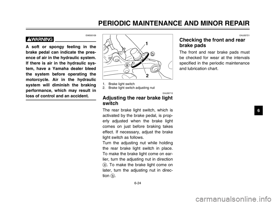
Rear brake light switch, adjustingThe rear brake light switch, which is
activated by the brake pedal, is prop-
erly adjusted when the brake light
comes on just before braking takes
effect. If necessary, adjust the brake
light switch as follows.
Turn the adjusting nut while holding
the rear brake light switch in place.
To make the brake light come on ear-
lier, turn the adjusting nut in direction
a. To make the brake light come on
later, turn the adjusting nut in direc-
tion b.
1. Brake light switch
2. Brake light switch adjusting nut
5PS-28199-E1 8/29/02 9:16 AM Page 69
Page 71 of 110
6-25
PERIODIC MAINTENANCE AND MINOR REPAIR
6
EAU00725
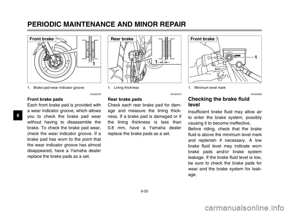
Front brake pads
Each front brake pad is provided with
a wear indicator groove, which allows
you to check the brake pad wear
without having to disassemble the
brake. To check the brake pad wear,
check the wear indicator groove. If a
brake pad has worn to the point that
the wear indicator groove has almost
disappeared, have a Yamaha dealer
replace the brake pads as a set.
1
1. Brake pad wear indicator groove
EAU04856
Checking the brake fluid
level
Brake fluid level, checkingInsufficient brake fluid may allow air
to enter the brake system, possibly
causing it to become ineffective.
Before riding, check that the brake
fluid is above the minimum level mark
and replenish if necessary. A low
brake fluid level may indicate worn
brake pads and/or brake system
leakage. If the brake fluid level is low,
be sure to check the brake pads for
wear and the brake system for leak-
age.
1
1. Minimum level mark
EAU04510
Rear brake pads
Check each rear brake pad for dam-
age and measure the lining thick-
ness. If a brake pad is damaged or if
the lining thickness is less than
0.8 mm, have a Yamaha dealer
replace the brake pads as a set.
1
1. Lining thickness
Front brakeRear brakeFront brake
5PS-28199-E1 8/29/02 9:16 AM Page 70
Page 72 of 110
6-26
PERIODIC MAINTENANCE AND MINOR REPAIR
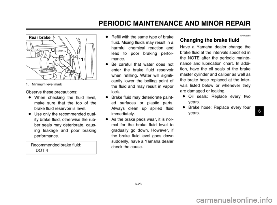
6 Observe these precautions:
8When checking the fluid level,
make sure that the top of the
brake fluid reservoir is level.
8Use only the recommended qual-
ity brake fluid, otherwise the rub-
ber seals may deteriorate, caus-
ing leakage and poor braking
performance.
1
1. Minimum level mark
EAU03985
Changing the brake fluidBrake fluid, changingHave a Yamaha dealer change the
brake fluid at the intervals specified in
the NOTE after the periodic mainte-
nance and lubrication chart. In addi-
tion, have the oil seals of the brake
master cylinder and caliper as well as
the brake hose replaced at the inter-
vals listed below or whenever they
are damaged or leaking.
8Oil seals: Replace every two
years.
8Brake hose: Replace every four
years. 8Refill with the same type of brake
fluid. Mixing fluids may result in a
harmful chemical reaction and
lead to poor braking perfor-
mance.
8Be careful that water does not
enter the brake fluid reservoir
when refilling. Water will signifi-
cantly lower the boiling point of
the fluid and may result in vapor
lock.
8Brake fluid may deteriorate paint-
ed surfaces or plastic parts.
Always clean up spilled fluid
immediately.
8As the brake pads wear, it is nor-
mal for the brake fluid level to
gradually go down. However, if
the brake fluid level goes down
suddenly, have a Yamaha dealer
check the cause.
Rear brake
Recommended brake fluid:
DOT 4
5PS-28199-E1 8/29/02 9:16 AM Page 71
Page 85 of 110
6-39
PERIODIC MAINTENANCE AND MINOR REPAIR
6
EAU01617
Front wheelWheel (front)
To remove the front wheelRemovingEW000122
w
8It is advisable to have a
Yamaha dealer service the
wheel.
8Securely support the motorcy-
cle so that there is no danger
of it falling over.
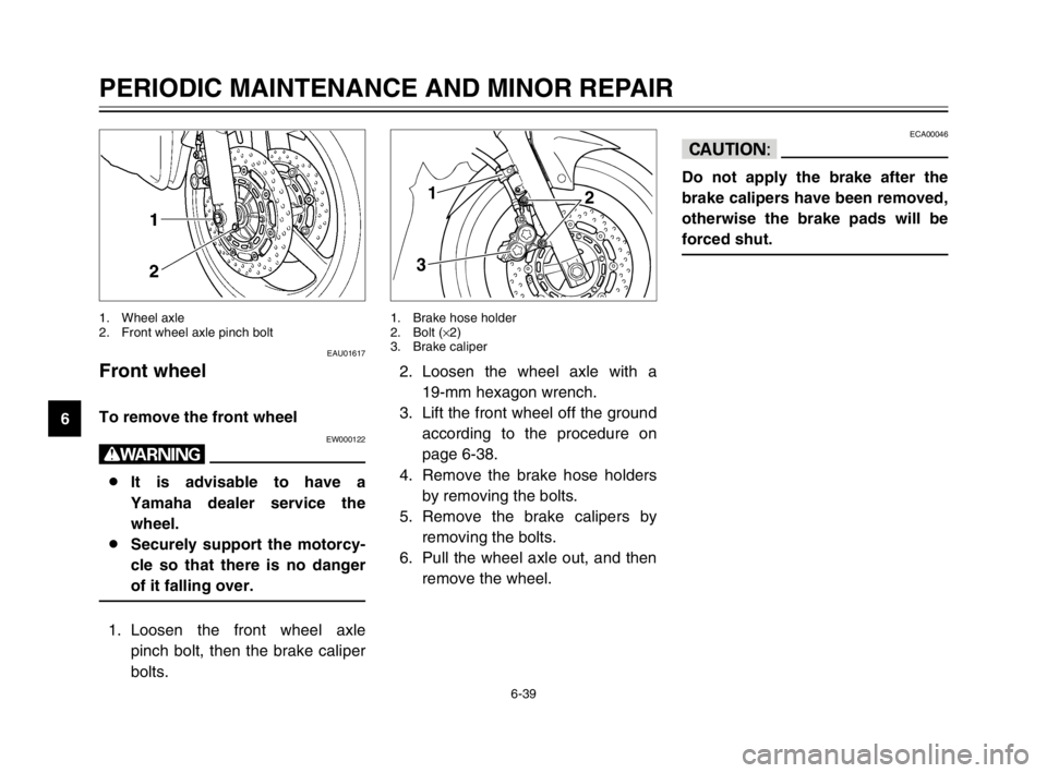
1. Loosen the front wheel axle
pinch bolt, then the brake caliper
bolts.
1. Wheel axle
2. Front wheel axle pinch bolt
ECA00046
cC
Do not apply the brake after the
brake calipers have been removed,
otherwise the brake pads will be
forced shut.
2. Loosen the wheel axle with a
19-mm hexagon wrench.
3. Lift the front wheel off the ground
according to the procedure on
page 6-38.
4. Remove the brake hose holders
by removing the bolts.
5. Remove the brake calipers by
removing the bolts.
6. Pull the wheel axle out, and then
remove the wheel.
1
3
2
1. Brake hose holder
2. Bolt (×2)
3. Brake caliper
5PS-28199-E1 8/29/02 9:17 AM Page 84
Page 86 of 110
6-40
PERIODIC MAINTENANCE AND MINOR REPAIR
6
EAU04376
To install the front wheelInstalling1. Lift the wheel up between the
fork legs.
2. Insert the wheel axle.
3. Lower the front wheel so that it is
on the ground.
4. Install the brake calipers by
installing the bolts.
NOTE:
Make sure that there is enough
space between the brake pads
before installing the brake calipers
onto the brake discs.
5. Install the brake hose holders by
installing the bolts.
6. Tighten the wheel axle, the front
wheel axle pinch bolt and the
brake caliper bolts to the speci-
fied torques.
EAU04455
Rear wheel
Wheel (rear)To remove the rear wheelRemovingEW000122
w
8It is advisable to have a
Yamaha dealer service the
wheel.
8Securely support the motorcy-
cle so that there is no danger
of it falling over.
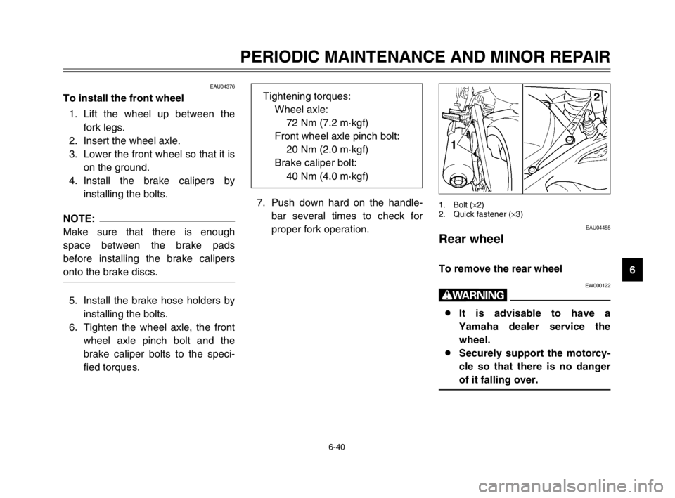
1. Bolt (×2)
2. Quick fastener (×3)7. Push down hard on the handle-
bar several times to check for
proper fork operation. Tightening torques:
Wheel axle:
72 Nm (7.2 m·kgf)
Front wheel axle pinch bolt:
20 Nm (2.0 m·kgf)
Brake caliper bolt:
40 Nm (4.0 m·kgf)
5PS-28199-E1 8/29/02 9:17 AM Page 85
Page 88 of 110

6-42
PERIODIC MAINTENANCE AND MINOR REPAIR
6 8. Pull the wheel axle out, and then
remove the wheel.
ECA00119
cC
Do not apply the brake after the
wheel has been removed together
with the brake disc, otherwise the
brake caliper pistons will be forced
out.
7. Install the drive chain cover by
installing the bolts and quick fas-
teners.
NOTE:
To install a quick fastener, push the
pin back so that it will protrude from
the fastener head, and then insert the
fastener and push the protruding pin
in until it is flush with the fastener
head.
EAU04456
To install the rear wheelInstalling1. Install the wheel by inserting the
wheel axle from the right hand
side.
NOTE:
Make sure that there is enough
space between the brake pads
before installing the wheel.
2. Install the drive chain onto the
rear sprocket.
3. Loosen the brake caliper bracket
bolt.
4. Adjust the drive chain slack.
(See page 6-27 for drive chain
slack adjustment procedures.)
5. Install the axle nut, and then
lower the rear wheel so that it is
on the ground.
6. Tighten the axle nut and the
brake caliper bracket bolt to the
specified torques.Tightening torques:
Axle nut:
150 Nm (15.0 m·kgf)
Brake caliper bracket bolt:
40 Nm (4.0 m·kgf)
1. Quick fastener
2. Pin
After removalBefore installation
5PS-28199-E1 8/29/02 9:17 AM Page 87
Page 107 of 110
INDEX
Checking ............................................6-27
Drive chain, lubricating .........................6-28
E
Engine break-in ......................................5-3
Engine idling speed ..............................6-17
Engine oil and oil filter element ..............6-8
F
Front and rear brake pads, checking ....6-24
Front fork, adjusting ..............................3-14
Front fork, checking ..............................6-31
Fuel ......................................................3-11
Fuel consumption, tips for reducing .......5-3
Fuel tank breather hose .......................3-12
Fuel tank cap ........................................3-10
Fuses, replacing ...................................6-34
H
Handlebar switches ................................3-7
Dimmer switch .....................................3-7
Engine stop switch ...............................3-8
Hazard switch ......................................3-8
Horn switch ..........................................3-8
Pass switch ..........................................3-7
Start switch ..........................................3-8
Turn signal switch ................................3-8
Headlight bulb, replacing ......................6-35
I
Identification numbers ............................9-1
Ignition circuit cut-off system ................3-19Indicator and warning lights ....................3-2
Fuel level warning symbol ...................3-2
Turn signal indicator lights ...................3-3
High beam indicator light .....................3-3
Neutral indicator light ...........................3-3
Engine trouble warning light ................3-3
Oil level warning light ...........................3-3
K
Key identification number .......................9-1
L
Luggage strap holders ..........................3-18
M
Main switch/steering lock .......................3-1
Model label .............................................9-2
P
Parking ...................................................5-4
Part locations ..........................................2-1
Periodic maintenance and lubrication
chart .....................................................6-2
Pre-operation check list ..........................4-1
R
Rear brake light switch, adjusting .........6-24
Rear suspension, lubricating ................6-31
S
Seat ......................................................3-13
Shift pedal ..............................................3-9A
Air filter element, replacing ...................6-16
Anti-theft alarm (optional) .......................3-7
B
Battery ..................................................6-33
Brake and clutch levers, checking
and lubricating ...................................6-30
Brake and shift pedals, checking
and lubricating ...................................6-30
Brake fluid level, checking ....................6-25
Brake fluid, changing ............................6-26
Brake lever .............................................3-9
Brake pedal ..........................................3-10
Brake pedal position, adjusting ............6-23
C
Cables, checking and lubricating ..........6-29
Care ........................................................7-1
Catalytic converter ................................3-12
Clutch lever ............................................3-9
Clutch lever free play, adjusting ...........6-22
Conversion table ....................................8-5
Coolant .................................................6-11
Checking ............................................6-11
Changing ...........................................6-13
Coolant temperature gauge ....................3-6
Cowlings and panels, removing
and installing ........................................6-5
D
Drive chain slack ..................................6-27
Adjusting ............................................6-27
5PS-28199-E1 8/29/02 9:17 AM Page 106