check engine YAMAHA TDM 900 2009 Owner's Manual
[x] Cancel search | Manufacturer: YAMAHA, Model Year: 2009, Model line: TDM 900, Model: YAMAHA TDM 900 2009Pages: 94, PDF Size: 3.75 MB
Page 71 of 94
PERIODIC MAINTENANCE AND ADJUSTMENT
6-26
2
3
4
5
67
8
9
EAU23272
Checking the front fork
The condition and operation of the front
fork must be checked as follows at the
intervals specified in the periodic main-
tenance and lubrication chart.
To check the condition
Check the inner tubes for scratches,
damage and excessive oil leakage.
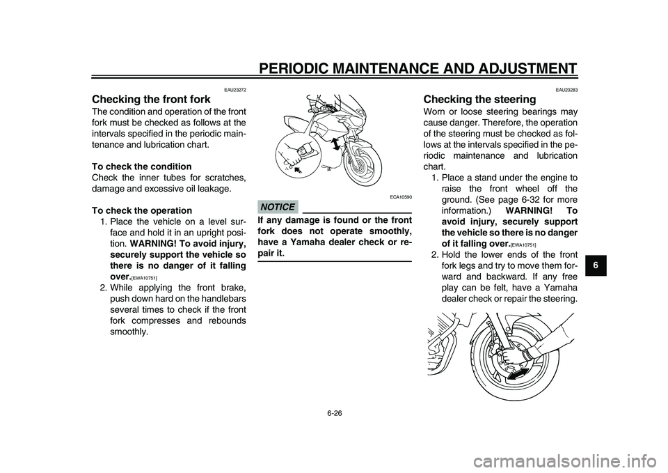
To check the operation
1. Place the vehicle on a level sur-
face and hold it in an upright posi-
tion.
WARNING! To avoid injury,
securely support the vehicle so
there is no danger of it falling
over.
[EWA10751]
2. While applying the front brake,
push down hard on the handlebars
several times to check if the front
fork compresses and rebounds
smoothly.
NOTICE
ECA10590
If any damage is found or the front
fork does not operate smoothly,
have a Yamaha dealer check or re-
pair it.
EAU23283
Checking the steering
Worn or loose steering bearings may
cause danger. Therefore, the operation
of the steering must be checked as fol-
lows at the intervals specified in the pe-
riodic maintenance and lubrication
chart.
1. Place a stand under the engine to
raise the front wheel off the
ground. (See page 6-32 for more
information.)
WARNING! To
avoid injury, securely support
the vehicle so there is no danger
of it falling over.
[EWA10751]
2. Hold the lower ends of the front
fork legs and try to move them for-
ward and backward. If any free
play can be felt, have a Yamaha
dealer check or repair the steering.
Page 77 of 94
PERIODIC MAINTENANCE AND ADJUSTMENT
6-32
2
3
4
5
67
8
9
EAU36451
Replacing an auxiliary light
bulb
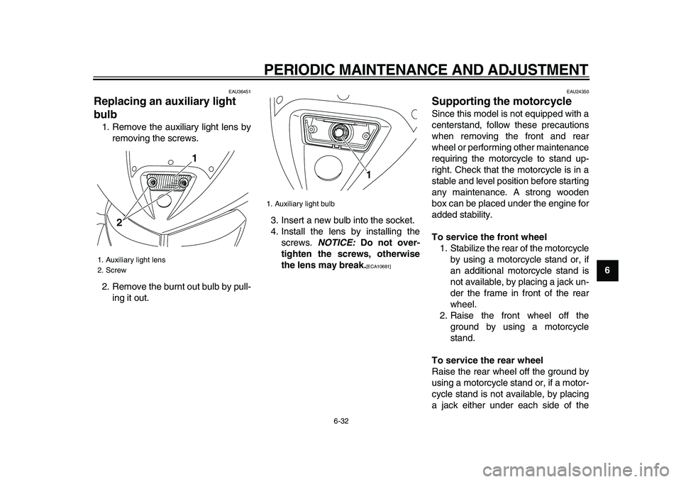
1. Remove the auxiliary light lens by
removing the screws.
2. Remove the burnt out bulb by pull-
ing it out.3. Insert a new bulb into the socket.
4. Install the lens by installing the
screws.
NOTICE:
Do not over-
tighten the screws, otherwise
the lens may break.
[ECA10681]
EAU24350
Supporting the motorcycle
Since this model is not equipped with a
centerstand, follow these precautions
when removing the front and rear
wheel or performing other maintenance
requiring the motorcycle to stand up-
right. Check that the motorcycle is in a
stable and level position before starting
any maintenance. A strong wooden
box can be placed under the engine for
added stability.
To service the front wheel
1. Stabilize the rear of the motorcycle
by using a motorcycle stand or, if
an additional motorcycle stand is
not available, by placing a jack un-
der the frame in front of the rear
wheel.
2. Raise the front wheel off the
ground by using a motorcycle
stand.
To service the rear wheel
Raise the rear wheel off the ground by
using a motorcycle stand or, if a motor-
cycle stand is not available, by placing
a jack either under each side of the
1. Auxiliary light lens
2. Screw
21
1. Auxiliary light bulb
1
Page 79 of 94
PERIODIC MAINTENANCE AND ADJUSTMENT
6-34
2
3
4
5
67
8
9
EAU42361
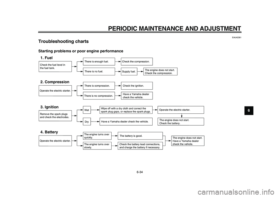
Troubleshooting charts
Starting problems or poor engine performance
Check the fuel level in
the fuel tank.1. Fuel
There is enough fuel.
There is no fuel.
Check the compression.
Supply fuel.
The engine does not start.
Check the compression.
Operate the electric starter.2. Compression
There is compression.
There is no compression.
Check the ignition.
Have a Yamaha dealer
check the vehicle.
Remove the spark plugs
and check the electrodes.3. Ignition
Wipe off with a dry cloth and correct the
spark plug gaps, or replace the spark plugs.
Have a Yamaha dealer check the vehicle.
The engine does not start.
Have a Yamaha dealer
check the vehicle.
The engine does not start.
Check the battery.
Operate the electric starter.4. Battery
The engine turns over
quickly.
The engine turns over
slowly.
The battery is good.Check the battery lead connections,
and charge the battery if necessary.
DryWet
Operate the electric starter.
Page 80 of 94
PERIODIC MAINTENANCE AND ADJUSTMENT
6-35
1
2
3
4
5
6
7
8
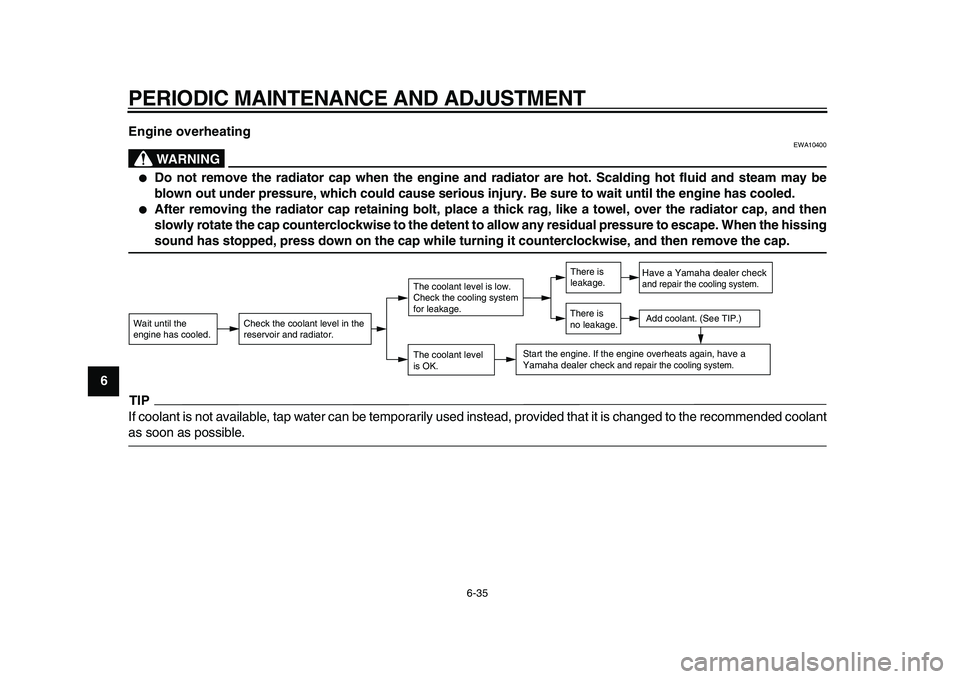
9Engine overheating
WARNING
EWA10400
●
Do not remove the radiator cap when the engine and radiator are hot. Scalding hot fluid and steam may be
blown out under pressure, which could cause serious injury. Be sure to wait until the engine has cooled.
●
After removing the radiator cap retaining bolt, place a thick rag, like a towel, over the radiator cap, and then
slowly rotate the cap counterclockwise to the detent to allow any residual pressure to escape. When the hissing
sound has stopped, press down on the cap while turning it counterclockwise, and then remove the cap.
TIP
If coolant is not available, tap water can be temporarily used instead, provided that it is changed to the recommended coolant
as soon as possible.
Wait until the
engine has cooled.
Check the coolant level in the
reservoir and radiator.
The coolant level
is OK.The coolant level is low.
Check the cooling system
for leakage.
Have a Yamaha dealer checkand repair the cooling system.Add coolant. (See TIP.)
Start the engine. If the engine overheats again,
have a
Yamaha dealer check
and repair the cooling system.
There is
leakage.
There is
no leakage.
Page 84 of 94
MOTORCYCLE CARE AND STORAGE
7-4
1
2
3
4
5
6
7
8
9
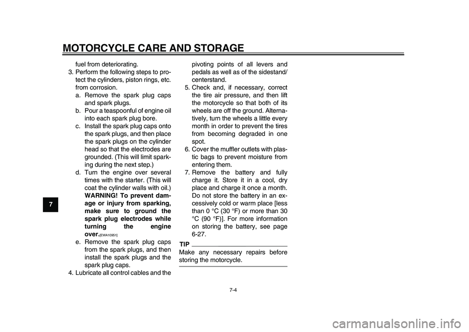
fuel from deteriorating.
3. Perform the following steps to pro-
tect the cylinders, piston rings, etc.
from corrosion.
a. Remove the spark plug caps
and spark plugs.
b. Pour a teaspoonful of engine oil
into each spark plug bore.
c. Install the spark plug caps onto
the spark plugs, and then place
the spark plugs on the cylinder
head so that the electrodes are
grounded. (This will limit spark-
ing during the next step.)
d. Turn the engine over several
times with the starter. (This will
coat the cylinder walls with oil.)
WARNING! To prevent dam-
age or injury from sparking,
make sure to ground the
spark plug electrodes while
turning the engine
over.
[EWA10951]
e. Remove the spark plug caps
from the spark plugs, and then
install the spark plugs and the
spark plug caps.
4. Lubricate all control cables and thepivoting points of all levers and
pedals as well as of the sidestand/
centerstand.
5. Check and, if necessary, correct
the tire air pressure, and then lift
the motorcycle so that both of its
wheels are off the ground. Alterna-
tively, turn the wheels a little every
month in order to prevent the tires
from becoming degraded in one
spot.
6. Cover the muffler outlets with plas-
tic bags to prevent moisture from
entering them.
7. Remove the battery and fully
charge it. Store it in a cool, dry
place and charge it once a month.
Do not store the battery in an ex-
cessively cold or warm place [less
than 0 °C (30 °F) or more than 30
°C (90 °F)]. For more information
on storing the battery, see page
6-27.
TIP
Make any necessary repairs before
storing the motorcycle.
Page 90 of 94
INDEX
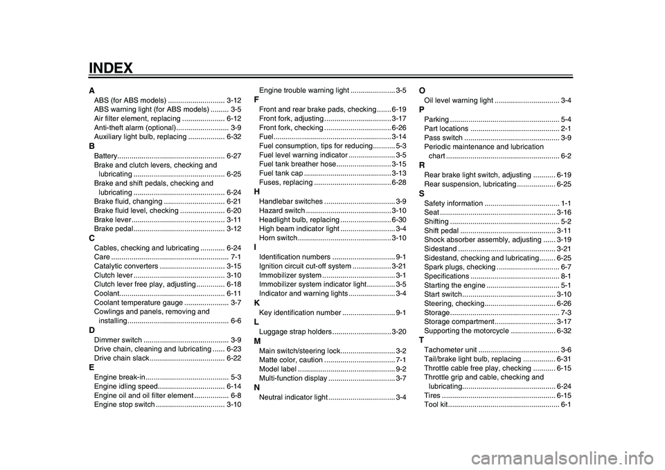
A
ABS (for ABS models) ............................ 3-12
ABS warning light (for ABS models) ......... 3-5
Air filter element, replacing ..................... 6-12
Anti-theft alarm (optional).......................... 3-9
Auxiliary light bulb, replacing .................. 6-32
B
Battery..................................................... 6-27
Brake and clutch levers, checking and
lubricating ............................................. 6-25
Brake and shift pedals, checking and
lubricating ............................................. 6-24
Brake fluid, changing .............................. 6-21
Brake fluid level, checking ...................... 6-20
Brake lever .............................................. 3-11
Brake pedal ............................................. 3-12
C
Cables, checking and lubricating ............ 6-24
Care .......................................................... 7-1
Catalytic converters ................................ 3-15
Clutch lever ............................................. 3-10
Clutch lever free play, adjusting .............. 6-18
Coolant.................................................... 6-11
Coolant temperature gauge ...................... 3-7
Cowlings and panels, removing and
installing.................................................. 6-6
D
Dimmer switch .......................................... 3-9
Drive chain, cleaning and lubricating ...... 6-23
Drive chain slack ..................................... 6-22
E
Engine break-in ......................................... 5-3
Engine idling speed................................. 6-14
Engine oil and oil filter element ................. 6-8
Engine stop switch .................................. 3-10Engine trouble warning light ...................... 3-5
F
Front and rear brake pads, checking ....... 6-19
Front fork, adjusting ................................. 3-17
Front fork, checking ................................. 6-26
Fuel.......................................................... 3-14
Fuel consumption, tips for reducing........... 5-3
Fuel level warning indicator ....................... 3-5
Fuel tank breather hose........................... 3-15
Fuel tank cap ........................................... 3-13
Fuses, replacing ...................................... 6-28
H
Handlebar switches ................................... 3-9
Hazard switch .......................................... 3-10
Headlight bulb, replacing ......................... 6-30
High beam indicator light ........................... 3-4
Horn switch .............................................. 3-10
I
Identification numbers ............................... 9-1
Ignition circuit cut-off system ................... 3-21
Immobilizer system .................................... 3-1
Immobilizer system indicator light.............. 3-5
Indicator and warning lights ....................... 3-4
K
Key identification number .......................... 9-1
L
Luggage strap holders ............................. 3-20
M
Main switch/steering lock........................... 3-2
Matte color, caution ................................... 7-1
Model label ................................................ 9-2
Multi-function display ................................. 3-7
N
Neutral indicator light ................................. 3-4
O
Oil level warning light ................................ 3-4
P
Parking ...................................................... 5-4
Part locations ............................................ 2-1
Pass switch ............................................... 3-9
Periodic maintenance and lubrication
chart ........................................................ 6-2
R
Rear brake light switch, adjusting ........... 6-19
Rear suspension, lubricating ................... 6-25
S
Safety information ..................................... 1-1
Seat ......................................................... 3-16
Shifting ...................................................... 5-2
Shift pedal ............................................... 3-11
Shock absorber assembly, adjusting ...... 3-19
Sidestand ................................................ 3-21
Sidestand, checking and lubricating........ 6-25
Spark plugs, checking ............................... 6-7
Specifications ............................................ 8-1
Starting the engine .................................... 5-1
Start switch .............................................. 3-10
Steering, checking................................... 6-26
Storage...................................................... 7-3
Storage compartment.............................. 3-17
Supporting the motorcycle ...................... 6-32
T
Tachometer unit ........................................ 3-6
Tail/brake light bulb, replacing ................ 6-31
Throttle cable free play, checking ........... 6-15
Throttle grip and cable, checking and
lubricating.............................................. 6-24
Tires ........................................................ 6-15
Tool kit....................................................... 6-1