oil filter YAMAHA TDR 125 2000 Owners Manual
[x] Cancel search | Manufacturer: YAMAHA, Model Year: 2000, Model line: TDR 125, Model: YAMAHA TDR 125 2000Pages: 104, PDF Size: 4.88 MB
Page 27 of 104
3-12
INSTRUMENT AND CONTROL FUNCTIONS
1
2
3
4
5
6
7
8
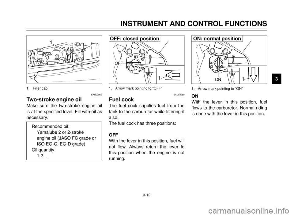
9ON1
1. Arrow mark pointing to “ON”
EAU03050
Fuel cock
The fuel cock supplies fuel from the
tank to the carburetor while filtering it
also.
The fuel cock has three positions:
OFF
With the lever in this position, fuel will
not flow. Always return the lever to
this position when the engine is not
running.ON
With the lever in this position, fuel
flows to the carburetor. Normal riding
is done with the lever in this position.
1
OFF
1. Arrow mark pointing to “OFF”
EAU02956
Two-stroke engine oil
Make sure the two-stroke engine oil
is at the specified level. Fill with oil as
necessary.
1
1. Filler cap
Recommended oil:
Yamalube 2 or 2-stroke
engine oil (JASO FC grade or
ISO EG-C, EG-D grade)
Oil quantity:
1.2 L
OFF: closed positionON: normal position
5AE-9-E3 (ENG) 4/11/0 11:06 AM Page 25
Page 45 of 104
PERIODIC MAINTENANCE AND MINOR REPAIR
Tool kit ...................................................................6-1
Periodic maintenance and lubrication ....................6-3
Cowling and panel removal and installation...........6-6
Cowling A, B ..........................................................6-7
Panel A ..................................................................6-7
Spark plug inspection.............................................6-8
Transmission oil .....................................................6-9
Cooling system ....................................................6-10
Changing the coolant ...........................................6-11
Air filter .................................................................6-13
Carburetor adjustment .........................................6-15
Idle speed adjustment ..........................................6-15
Throttle cable free play adjustment ......................6-16
Tires .....................................................................6-17
Wheels .................................................................6-19
Clutch lever free play adjustment.........................6-19
Front brake lever free play adjustment ................6-20
Rear brake pedal height adjustment ....................6-20
Brake light switch adjustment ..............................6-21
Checking the front and rear brake pads...............6-21
Inspecting the brake fluid level.............................6-22
Brake fluid replacement .......................................6-23
Drive chain slack check .......................................6-23
Drive chain slack adjustment ...............................6-24Drive chain lubrication............................................6-25
Cable inspection and lubrication ............................6-25
Throttle cable and grip lubrication ..........................6-26
Autolube pump adjustment ....................................6-26
Brake and shift pedal lubrication ............................6-26
Brake and clutch lever lubrication ..........................6-27
Sidestand lubrication..............................................6-27
Rear suspension lubrication...................................6-27
Front fork inspection ..............................................6-28
Steering inspection ................................................6-28
Wheel bearings ......................................................6-29
Battery....................................................................6-29
Fuse replacement ..................................................6-30
Headlight bulb replacement ...................................6-31
Taillight bulb replacement ......................................6-32
Turn signal light bulb replacement .........................6-32
Front wheel removal ..............................................6-33
Front wheel installation ..........................................6-34
Rear wheel removal ...............................................6-34
Rear wheel installation ...........................................6-35
Troubleshooting .....................................................6-36
Troubleshooting chart ............................................6-37
6
5AE-9-E3 (ENG) 4/11/0 11:06 AM Page 43
Page 50 of 104
6-5
PERIODIC MAINTENANCE AND MINOR REPAIR
6
7
8
9
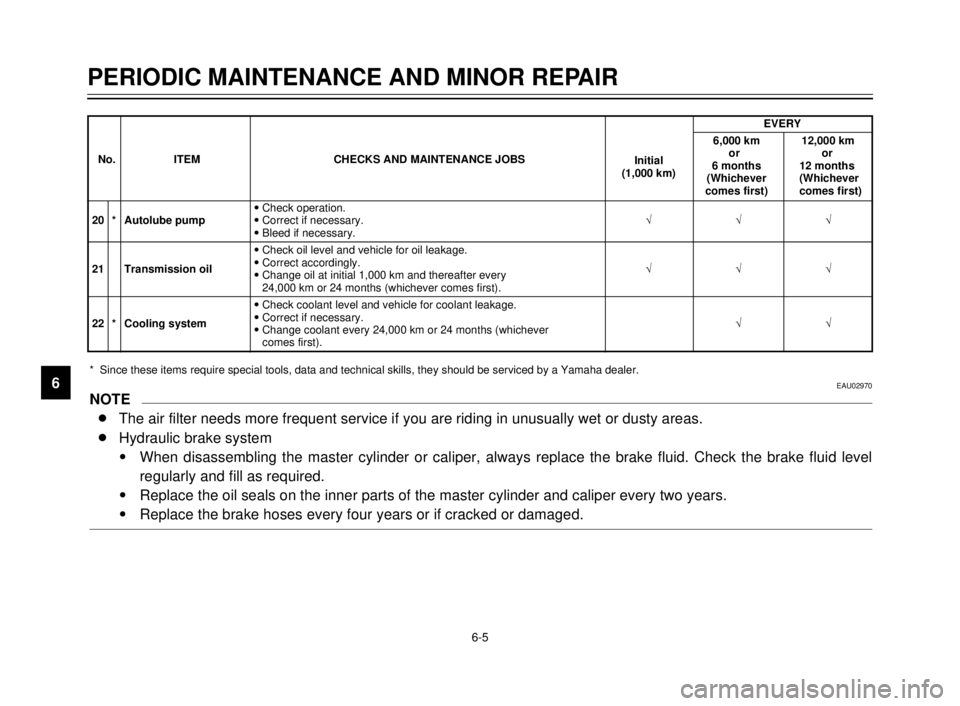
EVERY
6,000 km 12,000 km
No.
ITEM CHECKS AND MAINTENANCE JOBS
Initialor or
(1,000 km)6 months 12 months
(Whichever (Whichever
comes first) comes first)
9Check operation.
20 * Autolube pump9Correct if necessary.ÖÖÖ
9Bleed if necessary.
9Check oil level and vehicle for oil leakage.
21 Transmission oil9Correct accordingly.
ÖÖÖ
9Change oil at initial 1,000 km and thereafter every
24,000 km or 24 months (whichever comes first).
9Check coolant level and vehicle for coolant leakage.
22 * Cooling system9Correct if necessary.
ÖÖ
9Change coolant every 24,000 km or 24 months (whichever
comes first).
* Since these items require special tools, data and technical skills, they should be serviced by a Yamaha dealer.EAU02970
NOTE
8The air filter needs more frequent service if you are riding in unusually wet or dusty areas.
8Hydraulic brake system
9When disassembling the master cylinder or caliper, always replace the brake fluid. Check the brake fluid level
regularly and fill as required.
9Replace the oil seals on the inner parts of the master cylinder and caliper every two years.
9Replace the brake hoses every four years or if cracked or damaged.
5AE-9-E3 (ENG) 4/11/0 11:06 AM Page 48
Page 59 of 104
6-14
PERIODIC MAINTENANCE AND MINOR REPAIR
1
2
3
4
5
6
7
8
9
EW000071
w
8 8
Support the fuel tank carefully
during this procedure.
8 8
Do not tilt the fuel tank too
much or pull it too hard
because the fuel hose connec-
tions may become loose caus-
ing fuel leakage.
1
2
2
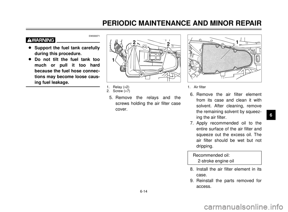
1. Relay (´2)
2. Screw (´7)
5. Remove the relays and the
screws holding the air filter case
cover.
1
1. Air filter
6. Remove the air filter element
from its case and clean it with
solvent. After cleaning, remove
the remaining solvent by squeez-
ing the air filter.
7. Apply recommended oil to the
entire surface of the air filter and
squeeze out the excess oil. The
air filter should be wet but not
dripping.
8. Install the air filter element in its
case.
9. Reinstall the parts removed for
access. Recommended oil:
2-stroke engine oil
5AE-9-E3 (ENG) 4/11/0 11:06 AM Page 57
Page 92 of 104
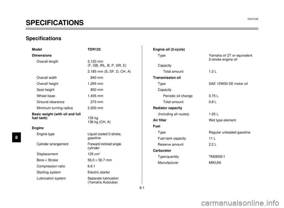
SPECIFICATIONS
1
2
3
4
5
6
7
8
9
Specifications
Model TDR125
Dimensions
Overall length 2,120 mm
(F, GB, IRL, B, P, GR, E)
2,185 mm (S, SF, D, CH, A)
Overall width 840 mm
Overall height 1,295 mm
Seat height 850 mm
Wheel base 1,405 mm
Ground clearance 270 mm
Minimum turning radius 2,200 mm
Basic weight (with oil and full
fuel tank)135 kg
136 kg (CH, A)
Engine
Engine type Liquid cooled 2-stroke,
gasoline
Cylinder arrangement Forward inclined single
cylinder
Displacement 125 cm
3
Bore ´Stroke 56.0 ´50.7 mm
Compression ratio 6.6:1
Starting system Electric starter
Lubrication system Separate lubrication
(Yamaha Autolube)Engine oil (2-cycle)
Type Yamaha oil 2T or equivalent
2-stroke engine oil
Capacity
Total amount 1.2 L
Transmission oil
Type SAE 10W30 SE motor oil
Capacity
Periodic oil change 0.75 L
Total amount 0.8 L
Radiator capacity
(Including all routes) 1.05 L
Air filterWet type element
Fuel
Type Regular unleaded gasoline
Fuel tank capacity 11 L
Reserve amount 2.2 L
Carburetor
Type/quantity TM28SS/1
Manufacturer MIKUNI
EAU01038
SPECIFICATIONS
8-1
5AE-9-E3 (ENG) 4/11/0 11:06 AM Page 90
Page 100 of 104
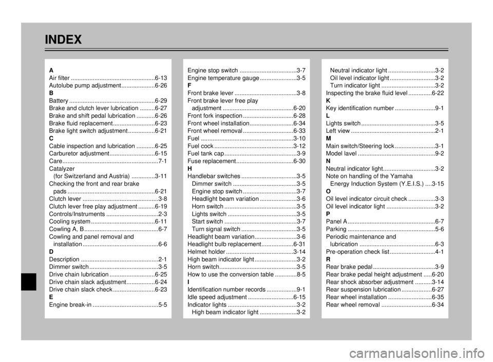
INDEX
Engine stop switch ..................................3-7
Engine temperature gauge ......................3-5
F
Front brake lever .....................................3-8
Front brake lever free play
adjustment ..........................................6-20
Front fork inspection ..............................6-28
Front wheel installation..........................6-34
Front wheel removal ..............................6-33
Fuel .......................................................3-10
Fuel cock ...............................................3-12
Fuel tank cap ...........................................3-9
Fuse replacement..................................6-30
H
Handlebar switches .................................3-5
Dimmer switch ......................................3-5
Engine stop switch ................................3-7
Headlight beam variation ......................3-6
Horn switch ...........................................3-5
Lights switch .........................................3-5
Start switch ...........................................3-7
Turn signal switch .................................3-5
Headlight beam variation.........................3-6
Headlight bulb replacement...................6-31
Helmet holder ........................................3-14
High beam indicator light .........................3-2
Horn switch..............................................3-5
How to use the conversion table .............8-5
I
Identification number records ..................9-1
Idle speed adjustment ...........................6-15
Indicator lights .........................................3-2
High beam indicator light ......................3-2Neutral indicator light ............................3-2
Oil level indicator light ...........................3-2
Turn indicator light ................................3-2
Inspecting the brake fluid level ..............6-22
K
Key identification number ........................9-1
L
Lights switch ............................................3-5
Left view ..................................................2-1
M
Main switch/Steering lock ........................3-1
Model lavel ..............................................9-2
N
Neutral indicator light...............................3-2
Note on handling of the Yamaha
Energy Induction System (Y.E.I.S.) ....3-15
O
Oil level indicator circuit check ................3-3
Oil level indicator light .............................3-2
P
Panel A ....................................................6-7
Parking ....................................................5-6
Periodic maintenance and
lubrication .............................................6-3
Pre-operation check list ...........................4-1
R
Rear brake pedal .....................................3-9
Rear brake pedal height adjustment .....6-20
Rear shock absorber adjustment ..........3-14
Rear suspension lubrication ..................6-27
Rear wheel installation ..........................6-35
Rear wheel removal ..............................6-34A
Air filter ..................................................6-13
Autolube pump adjustment....................6-26
B
Battery ...................................................6-29
Brake and clutch lever lubrication .........6-27
Brake and shift pedal lubrication ...........6-26
Brake fluid replacement.........................6-23
Brake light switch adjustment ................6-21
C
Cable inspection and lubrication ...........6-25
Carburetor adjustment...........................6-15
Care.........................................................7-1
Catalyzer
(for Switzerland and Austria) ..............3-11
Checking the front and rear brake
pads ....................................................6-21
Clutch lever .............................................3-8
Clutch lever free play adjustment ..........6-19
Controls/Instruments ...............................2-3
Cooling system ......................................6-11
Cowling A, B ............................................6-7
Cowling and panel removal and
installation .............................................6-6
D
Description ..............................................2-1
Dimmer switch .........................................3-5
Drive chain lubrication ...........................6-25
Drive chain slack adjustment.................6-24
Drive chain slack check .........................6-23
E
Engine break-in .......................................5-5
5AE-9-E3 (ENG) 4/11/0 11:06 AM Page 98