front wheel YAMAHA TENERE 700 2021 Owners Manual
[x] Cancel search | Manufacturer: YAMAHA, Model Year: 2021, Model line: TENERE 700, Model: YAMAHA TENERE 700 2021Pages: 104, PDF Size: 6.48 MB
Page 6 of 104

Table of contentsSafety information ............................ 1-1
Description ....................................... 2-1
Left view ......................................... 2-1
Right view ....................................... 2-2
Controls and instruments ............... 2-3
Instrument an d control functions ... 3-1
Immobilizer system......................... 3-1
Main switch/steering lock............... 3-2
Indicator lights and warning lights............................................ 3-3
Multi-function meter unit ................ 3-6
Handlebar switches ...................... 3-13
Clutch lever .................................. 3-15
Shift pedal .................................... 3-15
Brake lever.................................... 3-15
Brake pedal .................................. 3-16
ABS .............................................. 3-16
Fuel tank cap ................................ 3-17
Fuel ............................................... 3-18
Fuel tank overflow hose ............... 3-19
Catalytic converter ....................... 3-20
Seats ............................................ 3-20
Adjusting the headlight beams ..... 3-21
Adjusting the front fork ................. 3-22
Front fork bleeding ....................... 3-23
Adjusting the shock absorber assembly ................................... 3-24
Luggage strap holders ................. 3-26
Front fender ................................. 3-27 DC power outlets .......................... 3-27
Sidestand ...................................... 3-28
Ignition circuit cut-off system ....... 3-29
For your safety – pre-operation
checks ............................................... 4-1
Operation an d important ri din g
points ................................................. 5-1
Engine break-in ............................... 5-1
Starting the engine .......................... 5-2
Shifting ............................................ 5-3
Tips for reducing fuel consumption ................................ 5-4
Parking ............................................ 5-4
Perio dic maintenance an d
a d justment ........................................ 6-1
Tool kit ............................................ 6-2
Periodic maintenance charts .......... 6-3
Periodic maintenance chart for the emission control system .............. 6-3
General maintenance and
lubrication chart ........................... 6-5
Removing and installing cowlings... 6-9
Checking the spark plugs ............... 6-9
Canister ......................................... 6-10
Engine oil and oil filter cartridge.... 6-11
Why Yamalube .............................. 6-14
Coolant.......................................... 6-14 Replacing the air filter element and
cleaning the check hose ........... 6-15
Checking the throttle grip free play ............................................ 6-17
Valve clearance............................. 6-17
Tires .............................................. 6-17
Spoke wheels ............................... 6-20
Adjusting the clutch lever free
play ............................................ 6-20
Checking the brake lever free play ............................................ 6-21
Brake light switches ..................... 6-21
Checking the front and rear brake pads .......................................... 6-22
Checking the brake fluid level ...... 6-22
Changing the brake fluid .............. 6-24
Drive chain slack........................... 6-24
Cleaning and lubricating the drive chain.......................................... 6-26
Checking and lubricating the
cables ........................................ 6-26
Checking and lubricating the throttle grip and cable ............... 6-27
Checking and lubricating the brake and shift pedals............... 6-27
Checking and lubricating the
brake and clutch levers ............. 6-28
Checking and lubricating the sidestand................................... 6-28
Lubricating the rear suspension ... 6-29UBEHE0E0.book Page 1 Tuesday, December 8, 2020 6:57 PM
Page 7 of 104

Table of contents
Lubricating the swingarm
pivots .........................................6-29
Checking the front fork..................6-29
Checking the steering ...................6-30
Checking the wheel bearings ........6-30
Battery ...........................................6-31
Replacing the fuses .......................6-32
Vehicle lights .................................6-33
Tail/brake light ...............................6-34
Replacing a turn signal light bulb ............................................6-34
License plate light .........................6-35
Supporting the motorcycle............6-35
Troubleshooting ............................6-36
Troubleshooting chart ...................6-37
Motorcycle care an d stora ge ..........7-1
Matte color caution .........................7-1
Care .................................................7-1
Storage ............................................7-3
Specifications ....................................8-1
Consumer information .....................9-1
Identification numbers .....................9-1
Diagnostic connector ......................9-2
Vehicle data recording ....................9-2
In dex ................................................10-1
UBEHE0E0.book Page 2 Tuesday, December 8, 2020 6:57 PM
Page 12 of 104

Safety information
1-5
1Aftermarket Tires an
d Rims
The tires and rims that came with your
motorcycle were designed to match
the performance capabilities and to
provide the best combination of han-
dling, braking, and comfort. Other
tires, rims, sizes, and combinations
may not be appropriate. Refer to page
6-17 for tire specifications and more in-
formation on replacing your tires.
Transportin g the Motorcycle
Be sure to observe following instruc-
tions before transporting the motorcy-
cle in another vehicle. Remove all loose items from the
motorcycle.
Check that the fuel cock (if
equipped) is in the “OFF” position
and that there are no fuel leaks.
Point the front wheel straight
ahead on the trailer or in the truck
bed, and choke it in a rail to pre-
vent movement.
Shift the transmission in gear (for
models with a manual transmis-
sion).
Secure the motorcycle with tie-
downs or suitable straps that are
attached to solid parts of the mo-
torcycle, such as the frame or up-
per front fork triple clamp (and not,
for example, to rubber-mounted
handlebars or turn signals, or
parts that could break). Choose
the location for the straps carefully
so the straps will not rub against
painted surfaces during transport.
The suspension should be com-
pressed somewhat by the tie-
downs, if possible, so that the mo-
torcycle will not bounce exces-
sively during transport.
UBEHE0E0.book Page 5 Tuesday, December 8, 2020 6:57 PM
Page 30 of 104
Instrument and control functions
3-15
3
EAU12823
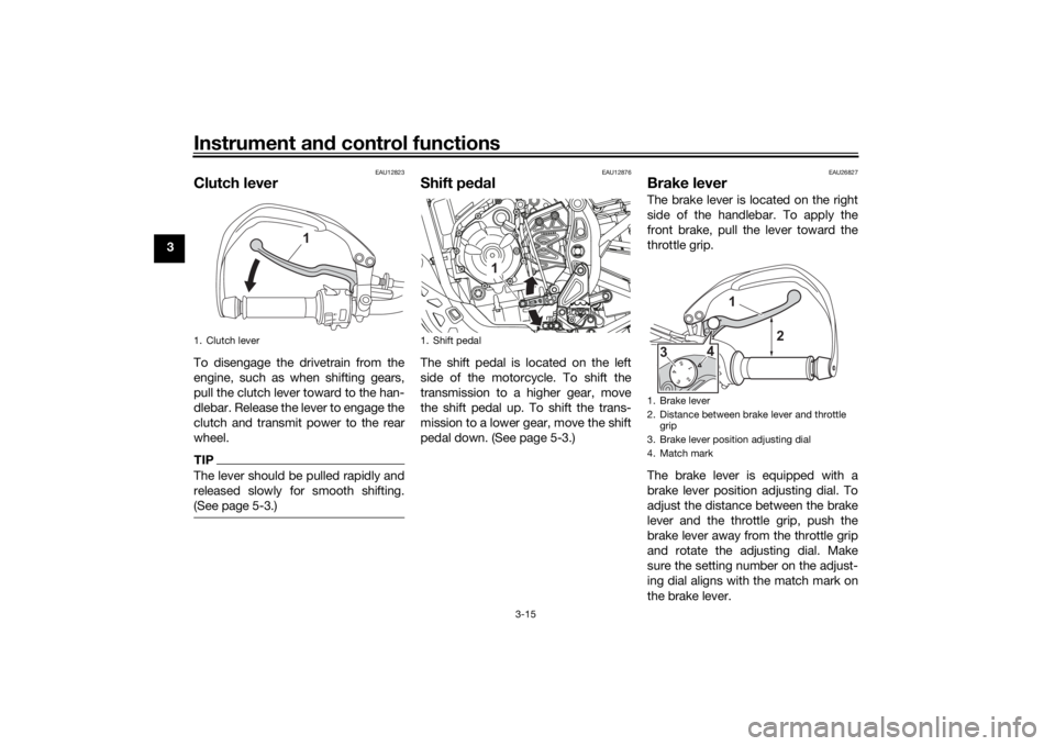
Clutch leverTo disengage the drivetrain from the
engine, such as when shifting gears,
pull the clutch lever toward to the han-
dlebar. Release the lever to engage the
clutch and transmit power to the rear
wheel.TIPThe lever should be pulled rapidly and
released slowly for smooth shifting.
(See page 5-3.)
EAU12876
Shift pe dalThe shift pedal is located on the left
side of the motorcycle. To shift the
transmission to a higher gear, move
the shift pedal up. To shift the trans-
mission to a lower gear, move the shift
pedal down. (See page 5-3.)
EAU26827
Brake leverThe brake lever is located on the right
side of the handlebar. To apply the
front brake, pull the lever toward the
throttle grip.
The brake lever is equipped with a
brake lever position adjusting dial. To
adjust the distance between the brake
lever and the throttle grip, push the
brake lever away from the throttle grip
and rotate the adjusting dial. Make
sure the setting number on the adjust-
ing dial aligns with the match mark on
the brake lever.
1. Clutch lever
1
1. Shift pedal
1
1. Brake lever
2. Distance between brake lever and throttle
grip
3. Brake lever position adjusting dial
4. Match mark
1
4
3
2
UBEHE0E0.book Page 15 Tuesday, December 8, 2020 6:57 PM
Page 31 of 104
Instrument and control functions
3-16
3
EAU12944
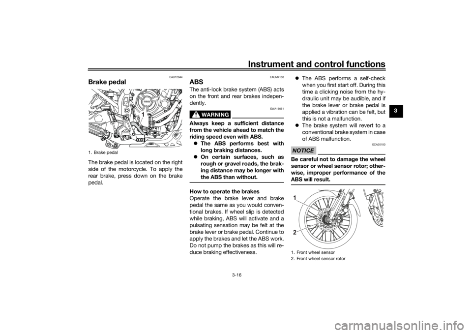
Brake ped alThe brake pedal is located on the right
side of the motorcycle. To apply the
rear brake, press down on the brake
pedal.
EAUM4100
ABSThe anti-lock brake system (ABS) acts
on the front and rear brakes indepen-
dently.
WARNING
EWA16051
Always keep a sufficient d istance
from the vehicle ahea d to match the
ri din g speed even with ABS.
The ABS performs best with
lon g b rakin g d istances.
On certain surfaces, such as
rou gh or g ravel roa ds, the b rak-
in g d istance may be lon ger with
the ABS than without.How to operate the brakes
Operate the brake lever and brake
pedal the same as you would conven-
tional brakes. If wheel slip is detected
while braking, ABS will activate and a
pulsating sensation may be felt at the
brake lever or brake pedal. Continue to
apply the brakes and let the ABS work.
Do not pump the brakes as this will re-
duce braking effectiveness.
The ABS performs a self-check
when you first start off. During this
time a clicking noise from the hy-
draulic unit may be audible, and if
the brake lever or brake pedal is
applied a vibration can be felt, but
this is not a malfunction.
The brake system will revert to a
conventional brake system in case
of ABS malfunction.
NOTICE
ECA20100
Be careful not to d amage the wheel
sensor or wheel sensor rotor; other-
wise, improper performance of the
ABS will result.
1. Brake pedal
1
1. Front wheel sensor
2. Front wheel sensor rotor21
UBEHE0E0.book Page 16 Tuesday, December 8, 2020 6:57 PM
Page 38 of 104
Instrument and control functions
3-23
3
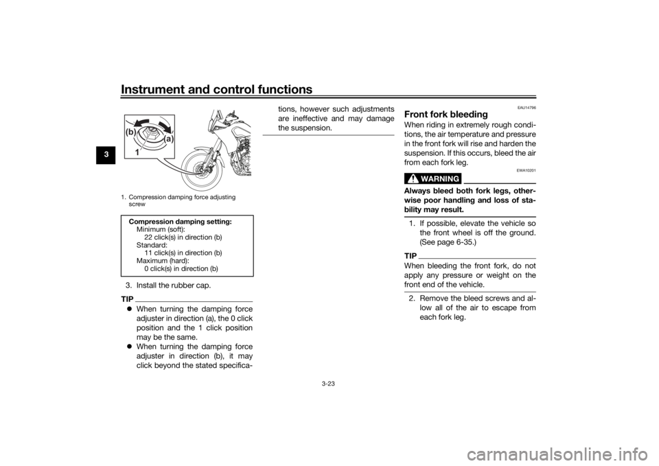
3. Install the rubber cap.
TIPWhen turning the damping force
adjuster in direction (a), the 0 click
position and the 1 click position
may be the same.
When turning the damping force
adjuster in direction (b), it may
click beyond the stated specifica- tions, however such adjustments
are ineffective and may damage
the suspension.
EAU14796
Front fork
blee din gWhen riding in extremely rough condi-
tions, the air temperature and pressure
in the front fork will rise and harden the
suspension. If this occurs, bleed the air
from each fork leg.
WARNING
EWA10201
Always blee d b oth fork le gs, other-
wise poor han dlin g an d loss of sta-
b ility may result.1. If possible, elevate the vehicle so
the front wheel is off the ground.
(See page 6-35.)TIPWhen bleeding the front fork, do not
apply any pressure or weight on the
front end of the vehicle.2. Remove the bleed screws and al-low all of the air to escape from
each fork leg.
1. Compression damping force adjusting screwCompression dampin g settin g:
Minimum (soft): 22 click(s) in direction (b)
Standard: 11 click(s) in direction (b)
Maximum (hard):
0 click(s) in direction (b)1 (a)
(b)
UBEHE0E0.book Page 23 Tuesday, December 8, 2020 6:57 PM
Page 39 of 104
Instrument and control functions
3-24
3
3. Install the bleed screws.
4. Lower the front wheel so that it is on the ground, and then put the
sidestand down.
EAUM4121
Adjustin g the shock a bsor ber
assem blyThis shock absorber assembly is
equipped with a spring preload adjust-
er and rebound and compression
damping force adjusters.NOTICE
ECA10102
To avoi d d amag ing the mechanism,
d o not attempt to turn b eyond the
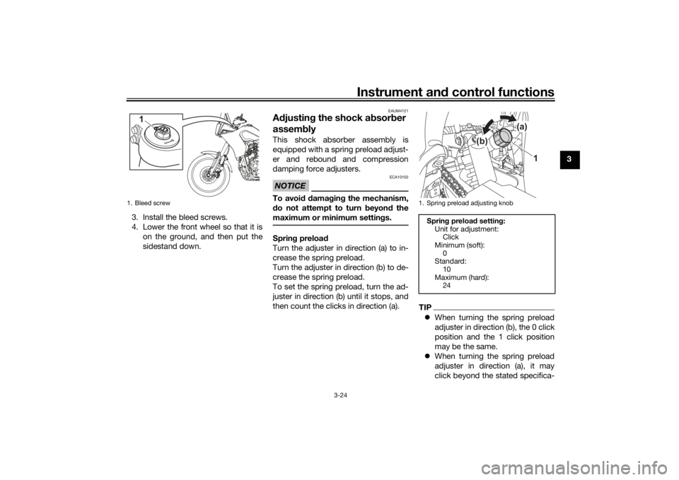
maximum or minimum settin gs.Sprin g preloa d
Turn the adjuster in direction (a) to in-
crease the spring preload.
Turn the adjuster in direction (b) to de-
crease the spring preload.
To set the spring preload, turn the ad-
juster in direction (b) until it stops, and
then count the clicks in direction (a).
TIP When turning the spring preload
adjuster in direction (b), the 0 click
position and the 1 click position
may be the same.
When turning the spring preload
adjuster in direction (a), it may
click beyond the stated specifica-
1. Bleed screw
1
1. Spring preload adjusting knob
Sprin g preloa d settin g:
Unit for adjustment: Click
Minimum (soft): 0
Standard:
10
Maximum (hard): 24
1
(b) (a)
UBEHE0E0.book Page 24 Tuesday, December 8, 2020 6:57 PM
Page 57 of 104

Periodic maintenance an d a djustment
6-5
6
EAU71353
General maintenance an d lu brication chartNO. ITEM CHECK OR MAINTENANCE JOB ODOMETER READING
ANNUAL
CHECK
1000 km
(600 mi) 10000 km
(6000 mi) 20000 km
(12000 mi) 30000 km
(18000 mi) 40000 km
(24000 mi)
1 *Dia
gnostic system
check • Perform dynamic inspection us-
ing Yamaha diagnostic tool.
• Check the error codes. √√√√√√
2 *Air filter element •Replace. √√
3 Air filter case check
hose • Clean.
√√√√√
4Clutch • Check operation.
•Adjust.
√√√√√
5 *Front brake • Check operation, fluid level, and
for fluid leakage.
• Replace brake pads if necessary. √√√√√√
6 *Rear brake • Check operation, fluid level, and
for fluid leakage.
• Replace brake pads if necessary. √√√√√√
7 *Brake hoses • Check for cracks or damage.
√√√√√
• Replace. Every 4 years
8 *Brake flui d • Change. Every 2 years
9 *Wheels • Check runout, spoke tightness
and for damage.
• Tighten spokes if necessary. √√√√√
10 *Tires • Check tread depth and for dam-
age.
• Replace if necessary.
• Check air pressure.
• Correct if necessary. √√√√√
UBEHE0E0.book Page 5 Tuesday, December 8, 2020 6:57 PM
Page 70 of 104
Periodic maintenance an d a djustment
6-18
6 wei
ght of ri der, passen ger, car-
g o, an d accessories approve d
for this mo del.
WARNING
EWA10512
Never overloa d your vehicle. Opera-
tion of an overloa ded vehicle coul d
cause an acci dent.
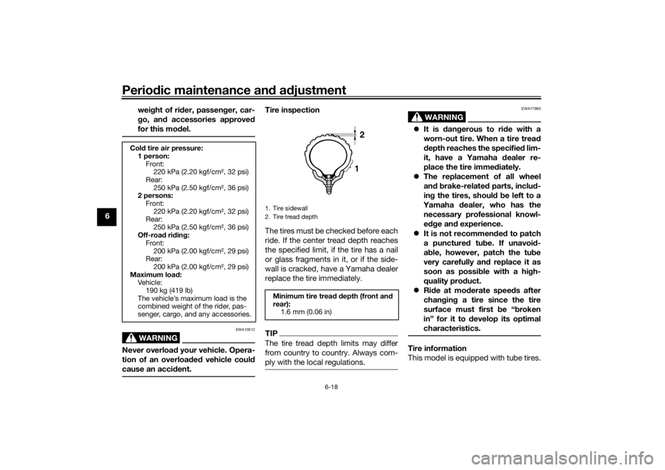
Tire inspection
The tires must be checked before each
ride. If the center tread depth reaches
the specified limit, if the tire has a nail
or glass fragments in it, or if the side-
wall is cracked, have a Yamaha dealer
replace the tire immediately.TIPThe tire tread depth limits may differ
from country to country. Always com-
ply with the local regulations.
WARNING
EWA17960
It is d angerous to ri de with a
worn-out tire. When a tire trea d
d epth reaches the specified lim-
it, have a Yamaha dealer re-
place the tire imme diately.
The replacement of all wheel
and b rake-relate d parts, inclu d-
in g the tires, shoul d b e left to a
Yamaha dealer, who has the
necessary professional knowl-
e dge an d experience.
It is not recommen ded to patch
a punctured tube. If unavoi d-
a b le, however, patch the tu be
very carefully an d replace it as
soon as possi ble with a hi gh-
quality pro duct.
Ride at mo derate speed s after
chan gin g a tire since the tire
surface must first be “ broken
in” for it to develop its optimal
characteristics.Tire information
This model is equipped with tube tires.
Col d tire air pressure:
1 person: Front:220 kPa (2.20 kgf/cm², 32 psi)
Rear: 250 kPa (2.50 kgf/cm², 36 psi)
2 persons:
Front:220 kPa (2.20 kgf/cm², 32 psi)
Rear:
250 kPa (2.50 kgf/cm², 36 psi)
Off-roa d ri din g:
Front:
200 kPa (2.00 kgf/cm², 29 psi)
Rear: 200 kPa (2.00 kgf/cm², 29 psi)
Maximum loa d:
Vehicle: 190 kg (419 lb)
The vehicle’s maximum load is the
combined weight of the rider, pas-
senger, cargo, and any accessories.
1. Tire sidewall
2. Tire tread depthMinimum tire trea d d epth (front an d
rear): 1.6 mm (0.06 in)
12
UBEHE0E0.book Page 18 Tuesday, December 8, 2020 6:57 PM
Page 82 of 104
Periodic maintenance an d a djustment
6-30
6
NOTICE
ECA10591
If any d amage is foun d or the front
fork does not operate smoothly,
have a Yamaha d ealer check or re-
pair it.
EAU23285
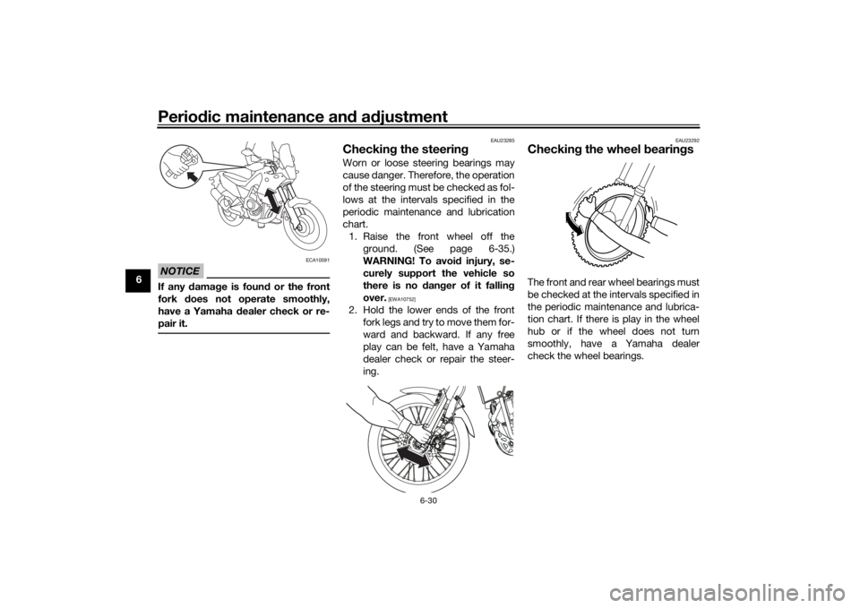
Checkin g the steerin gWorn or loose steering bearings may
cause danger. Therefore, the operation
of the steering must be checked as fol-
lows at the intervals specified in the
periodic maintenance and lubrication
chart.
1. Raise the front wheel off the ground. (See page 6-35.)
WARNING! To avoi d injury, se-
curely support the vehicle so
there is no dan ger of it fallin g
over.
[EWA10752]
2. Hold the lower ends of the front fork legs and try to move them for-
ward and backward. If any free
play can be felt, have a Yamaha
dealer check or repair the steer-
ing.
EAU23292
Checkin g the wheel bearin gsThe front and rear wheel bearings must
be checked at the intervals specified in
the periodic maintenance and lubrica-
tion chart. If there is play in the wheel
hub or if the wheel does not turn
smoothly, have a Yamaha dealer
check the wheel bearings.
UBEHE0E0.book Page 30 Tuesday, December 8, 2020 6:57 PM