check engine YAMAHA TMAX 2014 Owner's Manual
[x] Cancel search | Manufacturer: YAMAHA, Model Year: 2014, Model line: TMAX, Model: YAMAHA TMAX 2014Pages: 100, PDF Size: 3.01 MB
Page 62 of 100
PERIODIC MAINTENANCE AND ADJUSTMENT
6-13
1
2
3
4
56
7
8
9
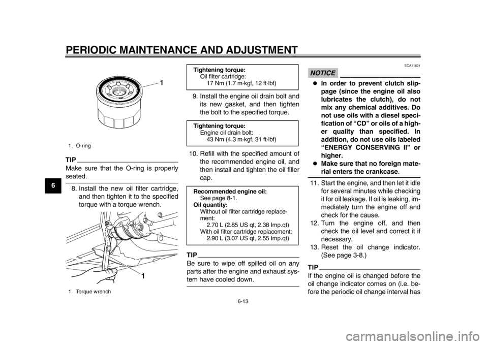
TIPMake sure that the O-ring is properlyseated.8. Install the new oil filter cartridge, and then tighten it to the specified
torque with a torque wrench. 9. Install the engine oil drain bolt and
its new gasket, and then tighten
the bolt to the specified torque.
10. Refill with the specified amount of the recommended engine oil, and
then install and tighten the oil filler
cap.
TIPBe sure to wipe off spilled oil on any
parts after the engine and exhaust sys-tem have cooled down.
NOTICE
ECA11621
In order to prevent clutch slip-
page (since the engine oil also
lubricates the clutch), do not
mix any chemical additives. Do
not use oils with a diesel speci-
fication of “CD” or oils of a high-
er quality than specified. In
addition, do not use oils labeled
“ENERGY CONSERVING II” or
higher.
Make sure that no foreign mate-rial enters the crankcase.
11. Start the engine, and then let it idle for several minutes while checking
it for oil leakage. If oil is leaking, im-
mediately turn the engine off and
check for the cause.
12. Turn the engine off, and then check the oil level and correct it if
necessary.
13. Reset the oil change indicator. (See page 3-8.)
TIPIf the engine oil is changed before the
oil change indicator comes on (i.e. be-
fore the periodic oil change interval has
1. O-ring
1. Torque wrench
1
1
Tightening torque:Oil filter cartridge:17 Nm (1.7 m·kgf, 12 ft·lbf)
Tightening torque: Engine oil drain bolt:43 Nm (4.3 m·kgf, 31 ft·lbf)
Recommended engine oil: See page 8-1.
Oil quantity: Without oil filter cartridge replace-
ment:2.70 L (2.85 US qt, 2.38 Imp.qt)
With oil filter cartridge replacement: 2.90 L (3.07 US qt, 2.55 Imp.qt)
59C-9-E2.book 13 ページ 2013年6月18日 火曜日 午後1時33分
Page 63 of 100
PERIODIC MAINTENANCE AND ADJUSTMENT
6-14
2
3
4
567
8
9
been reached), the indicator must be
reset after the oil change for the next
periodic oil change to be indicated at
the correct time.
EAU20071
CoolantThe coolant level should be checked
before each ride. In addition, the cool-
ant must be changed at the intervals
specified in the periodic maintenance
and lubrication chart.
EAU52021
To check the coolant level
1. Place the vehicle on the center- stand.TIP
The coolant level must be checked
on a cold engine since the level
varies with engine temperature.
Make sure that the vehicle is posi-
tioned straight up when checking
the coolant level. A slight tilt to theside can result in a false reading.
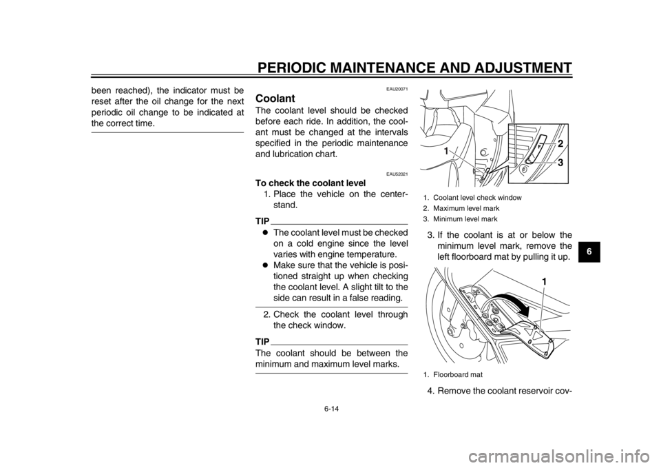
2. Check the coolant level through the check window.
TIPThe coolant should be between theminimum and maximum level marks. 3. If the coolant is at or below the
minimum level mark, remove the
left floorboard mat by pulling it up.
4. Remove the coolant reservoir cov-
1. Coolant level check window
2. Maximum level mark
3. Minimum level mark
1. Floorboard mat
2
3
1
1
59C-9-E2.book 14 ページ 2013年6月18日 火曜日 午後1時33分
Page 64 of 100
PERIODIC MAINTENANCE AND ADJUSTMENT
6-15
1
2
3
4
56
7
8
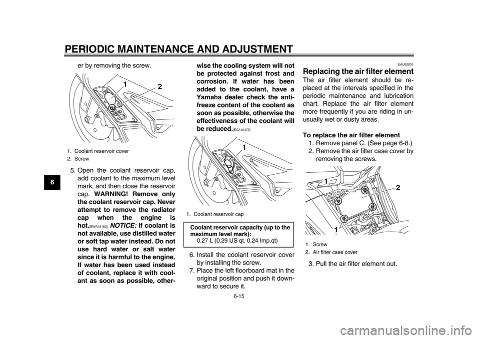
9er by removing the screw.
5. Open the coolant reservoir cap, add coolant to the maximum level
mark, and then close the reservoir
cap. WARNING! Remove only
the coolant reservoir cap. Never
attempt to remove the radiator
cap when the engine is
hot.
[EWA15162]
NOTICE: If coolant is
not available, use distilled water
or soft tap water instead. Do not
use hard water or salt water
since it is harmful to the engine.
If water has been used instead
of coolant, replace it with cool-
ant as soon as possible, other- wise the cooling system will not
be protected against frost and
corrosion. If water has been
added to the coolant, have a
Yamaha dealer check the anti-
freeze content of the coolant as
soon as possible, otherwise the
effectiveness of the coolant will
be reduced.
[ECA10473]
6. Install the coolant reservoir cover
by installing the screw.
7. Place the left floorboard mat in the original position and push it down-
ward to secure it.
EAU52031
Replacing the air filter elementThe air filter element should be re-
placed at the intervals specified in the
periodic maintenance and lubrication
chart. Replace the air filter element
more frequently if you are riding in un-
usually wet or dusty areas.
To replace the air filter element1. Remove panel C. (See page 6-8.)
2. Remove the air filter case cover by removing the screws.
3. Pull the air filter element out.
1. Coolant reservoir cover
2. Screw
1 2
1. Coolant reservoir cap Coolant reservoir capacity (up to the
maximum level mark):
0.27 L (0.29 US qt, 0.24 Imp.qt)
1
1. Screw
2. Air filter case cover
1
1 2
59C-9-E2.book 15 ページ 2013年6月18日 火曜日 午後1時33分
Page 65 of 100
PERIODIC MAINTENANCE AND ADJUSTMENT
6-16
2
3
4
567
8
9
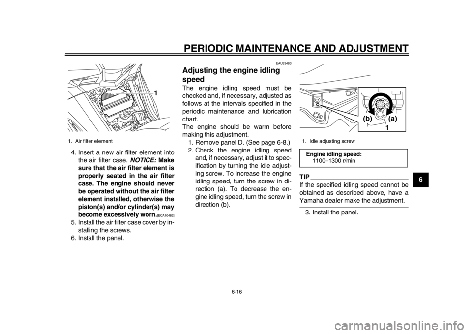
4. Insert a new air filter element into
the air filter case. NOTICE: Make
sure that the air filter element is
properly seated in the air filter
case. The engine should never
be operated without the air filter
element installed, otherwise the
piston(s) and/or cylinder(s) may
become excessively worn.
[ECA10482]
5. Install the air filter case cover by in- stalling the screws.
6. Install the panel.
EAU33483
Adjusting the engine idling
speedThe engine idling speed must be
checked and, if necessary, adjusted as
follows at the intervals specified in the
periodic maintenance and lubrication
chart.
The engine should be warm before
making this adjustment.
1. Remove panel D. (See page 6-8.)
2. Check the engine idling speed and, if necessary, adjust it to spec-
ification by turning the idle adjust-
ing screw. To increase the engine
idling speed, turn the screw in di-
rection (a). To decrease the en-
gine idling speed, turn the screw in
direction (b).
TIPIf the specified idling speed cannot be
obtained as described above, have aYamaha dealer make the adjustment.
3. Install the panel.
1. Air filter element
1
1. Idle adjusting screw Engine idling speed: 1100–1300 r/min
1(a)(b)
59C-9-E2.book 16 ページ 2013年6月18日 火曜日 午後1時33分
Page 66 of 100
PERIODIC MAINTENANCE AND ADJUSTMENT
6-17
1
2
3
4
56
7
8
9
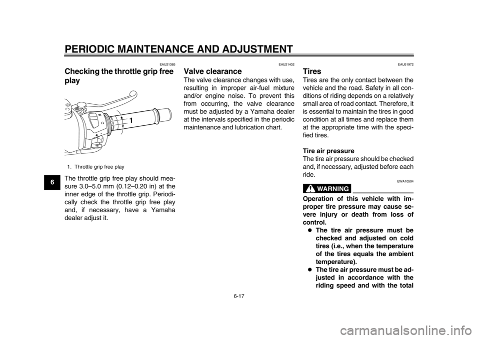
EAU21385
Checking the throttle grip free
playThe throttle grip free play should mea-
sure 3.0–5.0 mm (0.12–0.20 in) at the
inner edge of the throttle grip. Periodi-
cally check the throttle grip free play
and, if necessary, have a Yamaha
dealer adjust it.
EAU21402
Valve clearanceThe valve clearance changes with use,
resulting in improper air-fuel mixture
and/or engine noise. To prevent this
from occurring, the valve clearance
must be adjusted by a Yamaha dealer
at the intervals specified in the periodic
maintenance and lubrication chart.
EAU51972
TiresTires are the only contact between the
vehicle and the road. Safety in all con-
ditions of riding depends on a relatively
small area of road contact. Therefore, it
is essential to maintain the tires in good
condition at all times and replace them
at the appropriate time with the speci-
fied tires.
Tire air pressure
The tire air pressure should be checked
and, if necessary, adjusted before each
ride.
WARNING
EWA10504
Operation of this vehicle with im-
proper tire pressure may cause se-
vere injury or death from loss of
control.
The tire air pressure must be
checked and adjusted on cold
tires (i.e., when the temperature
of the tires equals the ambient
temperature).
The tire air pressure must be ad-
justed in accordance with the
riding speed and with the total
1. Throttle grip free play
1
59C-9-E2.book 17 ページ 2013年6月18日 火曜日 午後1時33分
Page 86 of 100
PERIODIC MAINTENANCE AND ADJUSTMENT
6-37
1
2
3
4
56
7
8
9
EAU42505
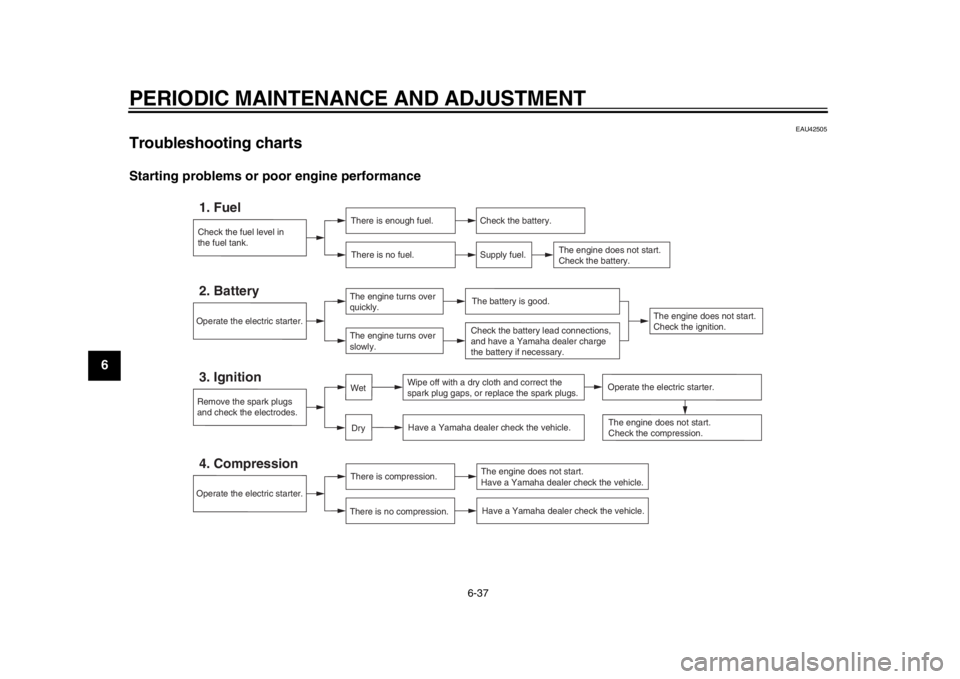
Troubleshooting chartsStarting problems or poor engine performance
Check the fuel level in
the fuel tank.1. Fuel
There is enough fuel.There is no fuel.
Check the battery.
Supply fuel.
The engine does not start.
Check the battery.
Remove the spark plugs
and check the electrodes.3. Ignition
Wipe off with a dry cloth and correct the
spark plug gaps, or replace the spark plugs.
Have a Yamaha dealer check the vehicle.
Operate the electric starter.4. Compression
There is compression.
There is no compression.
The engine does not start.
Have a Yamaha dealer check the vehicle.Have a Yamaha dealer check the vehicle.
The engine does not start.
Check the compression.
Operate the electric starter.2. Battery
The engine turns over
quickly.
The engine turns over
slowly.
The engine does not start.
Check the ignition.
The battery is good.Check the battery lead connections,
and have a Yamaha dealer charge
the battery if necessary.
DryWet
Operate the electric starter.
59C-9-E2.book 37 ページ 2013年6月18日 火曜日 午後1時33分
Page 87 of 100
PERIODIC MAINTENANCE AND ADJUSTMENT
6-38
2
3
4
567
8
9
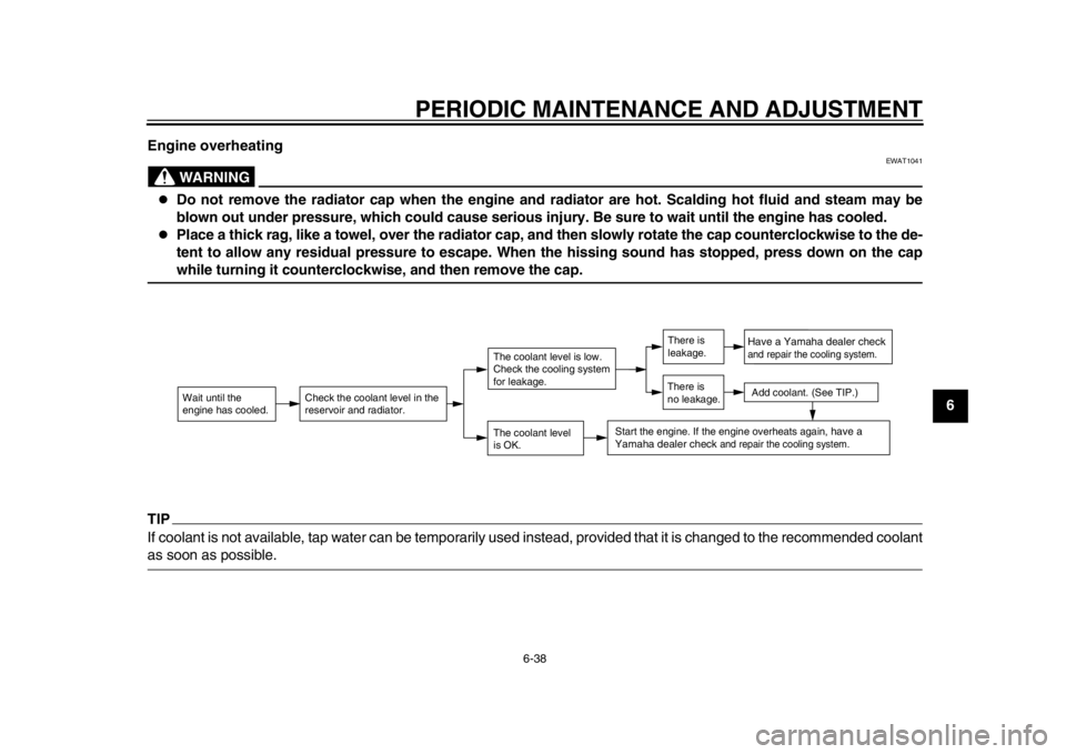
Engine overheating
WARNING
EWAT1041
Do not remove the radiator cap when the engine and radiator are hot. Scalding hot fluid and steam may be
blown out under pressure, which could cause serious injury. Be sure to wait until the engine has cooled.
Place a thick rag, like a towel, over the radiator cap, and then slowly rotate the cap counterclockwise to the de-
tent to allow any residual pressure to escape. When the hissing sound has stopped, press down on the capwhile turning it counterclockwise, and then remove the cap.
TIPIf coolant is not available, tap water can be temporarily
used instead, provided that it is changed to the recommended coolantas soon as possible.
Wait until the
engine has cooled.
Check the coolant level in the
reservoir and radiator.
The coolant level
is OK.The coolant level is low.
Check the cooling system
for leakage.
Have a Yamaha dealer checkand repair the cooling system.Add coolant. (See TIP.)
Start the engine. If the engine overheats again,
have a
Yamaha dealer check
and repair the cooling system.
There is
leakage.
There is
no leakage.
59C-9-E2.book 38 ページ 2013年6月18日 火曜日 午後1時33分
Page 91 of 100
SCOOTER CARE AND STORAGE
7-4
2
3
4
5
678
9
stabilizer (if available) to prevent
the fuel tank from rusting and the
fuel from deteriorating.
3. Perform the following steps to pro- tect the cylinders, piston rings, etc.
from corrosion.
a. Remove the spark plug caps and the spark plugs.
b. Pour a teaspoonful of engine oil into the spark plug bores.
c. Install the spark plug caps onto the spark plugs, and then place
the spark plugs on the cylinder
head so that the electrodes are
grounded. (This will limit spark-
ing during the next step.)
d. Turn the engine over several times with the starter. (This will
coat the cylinder walls with oil.)
e. Remove the spark plug caps from the spark plugs, and then
install the spark plugs and the
spark plug caps. WARNING!
To prevent damage or injury
from sparking, make sure to
ground the spark plug elec-
trodes while turning the en-
gine over.
[EWA10952]
4. Lubricate all control cables and the pivoting points of all levers and
pedals as well as of the sidestand/
centerstand.
5. Check and, if necessary, correct the tire air pressure, and then lift
the scooter so that both of its
wheels are off the ground. Alterna-
tively, turn the wheels a little every
month in order to prevent the tires
from becoming degraded in one
spot.
6. Cover the muffler outlet with a plastic bag to prevent moisture
from entering it.
7. Remove the battery and fully charge it. Store it in a cool, dry
place and charge it once a month.
Do not store the battery in an ex-
cessively cold or warm place [less
than 0 C (30 F) or more than 30
C (90 F)]. For more information
on storing the battery, see page
6-28.
TIPMake any necessary repairs beforestoring the scooter.
59C-9-E2.book 4 ページ 2013年6月18日 火曜日 午後1時33分
Page 96 of 100

INDEXAABS (for ABS models) .............................3-15
ABS warning light (for ABS models) ..........3-3
Acceleration and deceleration....................5-3
Air filter element, replacing ......................6-15
Auxiliary light bulb, replacing ...................6-35BBattery......................................................6-28
Brake fluid, changing ...............................6-24
Brake fluid level, checking .......................6-23
Brake lever, front......................................3-13
Brake lever, rear ......................................3-14
Brake levers, lubricating...........................6-25
Braking .......................................................5-3CCables, checking and lubricating .............6-24
Care ...........................................................7-1
Catalytic converter ...................................3-19
Centerstand and sidestand, checking and lubricating .......................................6-26
Coolant.....................................................6-14DDimmer switch .........................................3-12
Drive belt slack.........................................6-24EEngine break-in ..........................................5-4
Engine idling speed..................................6-16
Engine oil and oil filter cartridge ...............6-11
Engine stop switch ...................................3-13
Engine trouble warning light.......................3-3FFront and rear brak e lever free play,
checking ................................................6-20
Front and rear brake pads, checking .......6-22 Front fork, checking ................................. 6-26
Fuel.......................................................... 3-17
Fuel consumption, tips
for reducing........... 5-4
Fuel tank cap ........................................... 3-16
Fuses, replacing ...................................... 6-30
HHandlebar switches ................................. 3-12
Hazard switch .......................................... 3-13
Headlight bulb, replacing ......................... 6-32
Helmet holder .......................................... 3-21
High beam indicator light ........................... 3-3
Horn switch .............................................. 3-13IIdentification numbers ............................... 9-1
Ignition circuit cut-off system ................... 3-26
Immobilizer system .................................... 3-1
Immobilizer system indicator light.............. 3-4
Indicator lights and warning lights ............. 3-3LLicense plate light bulb, replacing ........... 6-34MMain switch/steering lock........................... 3-2
Maintenance and lubrication, periodic ....... 6-4
Maintenance, emission control system...... 6-3
Matte color, caution ................................... 7-1
Model label ................................................ 9-1
Multi-function display ................................. 3-5PPanels, removing and installing ................. 6-8
Parking ...................................................... 5-5
Part locations ............................................. 2-1
Pass switch.............................................. 3-12RRear brake lock cable, adjusting ............. 6-21 Rear brake lock, checking ....................... 6-21
Rear brake lock lever .............................. 3-15
Rear view mirrors .................................... 3-25
Rider backrest, adjusting......................... 3-20
SSafe-riding points ...................................... 1-5
Safety information ..................................... 1-1
Seat ......................................................... 3-19
Shock absorber assembly ....................... 3-25
Sidestand ................................................ 3-26
Spark plugs, checking ............................. 6-10
Specifications ............................................ 8-1
Speedometer............................................. 3-5
Starting off ................................................. 5-2
Starting the engine .................................... 5-1
Start switch.............................................. 3-13
Steering, checking................................... 6-27
Storage...................................................... 7-3
Storage compartments ............................ 3-21TTachometer ............................................... 3-5
Tail/brake light ......................................... 6-33
Throttle grip and cable, checking and
lubricating ............................................. 6-25
Throttle grip free play, checking .............. 6-17
Tires ........................................................ 6-17
Tool kit....................................................... 6-2
Troubleshooting ...................................... 6-35
Troubleshooting charts............................ 6-37
Turn signal indicator lights ........................ 3-3
Turn signal light bulb (f ront), replacing .... 6-33
Turn signal switch ................................... 3-12VValve clearance....................................... 6-17
59C-9-E2.book 2 ページ 2013年6月18日 火曜日 午後1時33分