lights YAMAHA TMAX 2014 Owners Manual
[x] Cancel search | Manufacturer: YAMAHA, Model Year: 2014, Model line: TMAX, Model: YAMAHA TMAX 2014Pages: 100, PDF Size: 3.01 MB
Page 6 of 100

TABLE OF CONTENTSSAFETY INFORMATION................... 1-1
Further safe-riding points................. 1-5
DESCRIPTION ................................... 2-1
Left view .......................................... 2-1
Right view ........................................ 2-2
Controls and instrument s................. 2-3
INSTRUMENT AND CONTROL
FUNCTIONS ....................................... 3-1
Immobilizer system ....... ................... 3-1
Main switch/steering lock................. 3-2
Indicator lights and warning lights ............................................. 3-3
Speedometer ................................... 3-5
Tachometer ..................................... 3-5
Multi-function display ....................... 3-5
Handlebar switches ....................... 3-12
Front brake lever ........................... 3-13
Rear brake lever ............................ 3-14
Rear brake lock lever..................... 3-15
ABS (for ABS models) .. ................. 3-15
Fuel tank cap ................................. 3-16
Fuel................................................ 3-17
Catalytic converter ......................... 3-19
Seat ............................................... 3-19
Adjusting the rider backrest ........... 3-20
Helmet holder ................................ 3-21
Storage compartments .................. 3-21
Windshield ..................................... 3-23
Rear view mirrors .......................... 3-25 Shock absorber assembly ............. 3-25
Sidestand ...................................... 3-26
Ignition circuit cut-
off system ......... 3-26
FOR YOUR SAFETY –
PRE-OPERATION CHECKS ............. 4-1
OPERATION AND IMPORTANT
RIDING POINTS ................................. 5-1
Starting the engine .......................... 5-1
Starting off ....................................... 5-2
Acceleration and deceleration ......... 5-3
Braking ............................................ 5-3
Tips for reducing fuel
consumption ................................ 5-4
Engine break-in ............................... 5-4
Parking ............................................ 5-5
PERIODIC MAINTENANCE AND
ADJUSTMENT ................................... 6-1
Owner’s tool kit................................ 6-2
Periodic maintenance chart for the emission control system .............. 6-3
General maintenance and lubrication chart ........................... 6-4
Removing and installing panels ...... 6-8
Checking the spark plugs .............. 6-10
Engine oil and oil filter cartridge .... 6-11
Coolant .......................................... 6-14
Replacing the air filter element...... 6-15 Adjusting the engine idling
speed............ ............................ .. 6-16
Checking the throttle grip free play ............................................. 6-17
Valve clearance ............................. 6-17
Tires ............................................... 6-17
Cast wheels ................................... 6-19
Checking the front and rear brake
lever free play ............................. 6-20
Adjusting the rear brake lock cable ........................................... 6-21
Checking the rear brake lock ......... 6-21
Checking the front and rear brake pads............................................ 6-22
Checking the brake fluid level ........ 6-23
Changing the brake fluid ................ 6-24
Drive belt slack .............................. 6-24
Checking and lubricating the cables ......................................... 6-24
Checking and lubricating the
throttle grip and cable ................. 6-25
Lubricating the front and rear brake levers ................................ 6-25
Checking and lubricating the centerstand and sidestand ......... 6-26
Checking the front fork................... 6-26
Checking the steering .................... 6-27
Checking the wheel bearings......... 6-27
Battery ........................................... 6-28
Replacing the fuses ....................... 6-30
Replacing the headlight bulb ......... 6-3259C-9-E2.book 1 ページ 2013年6月18日 火曜日 午後1時33分
Page 11 of 100

1-4
1
SAFETY INFORMATION
Aftermarket Parts, Accessories,
and Modifications
While you may find aftermarket prod-
ucts similar in design and quality to
genuine Yamaha accessories, recog-
nize that some aftermarket accessories
or modifications are not suitable be-
cause of potential safety hazards to you
or others. Installing aftermarket prod-
ucts or having other modifications per-
formed to your vehicle that change any
of the vehicle’s design or operation
characteristics can put you and others
at greater risk of serious injury or death.
You are responsible for injuries related
to changes in the vehicle.
Keep the following guidelines in mind,
as well as those provided under “Load-
ing” when mounting accessories.
Never install accessories or carry
cargo that would impair the perfor-
mance of your scooter. Carefully
inspect the accessory before using
it to make sure that it does not in
any way reduce ground clearance
or cornering clearance, limit sus-
pension travel, steering travel or
control operation, or obscure lights
or reflectors. Accessories fitted to the handle-
bar or the front fork area can
create instability due to improper
weight distribution or aerody-
namic changes. If accessories
are added to the handlebar or
front fork area, they must be as
lightweight as possible and
should be kept to a minimum.
Bulky or large accessories may seriously affect the stability of
the scooter due to aerodynamic
effects. Wind may attempt to lift
the scooter, or the scooter may
become unstable in cross
winds. These accessories may
also cause instability when
passing or being passed by
large vehicles.
Certain accessories can dis- place the operator from his or
her normal riding position. This
improper position limits the free-
dom of movement of the opera-
tor and may limit control ability,
therefore, such accessories are
not recommended.
Use caution when adding electri-
cal accessories. If electrical acces- sories exceed the capacity of the
scooter’s electrical system, an
electric failure could result, which
could cause a dangerous loss of
lights or engine power.
Aftermarket Tires and Rims
The tires and rims that came with your
scooter were designed to match the
performance capabilities and to provide
the best combination of handling, brak-
ing, and comfort. Other tires, rims, siz-
es, and combinations may not be
appropriate. Refer to page 6-17 for tire
specifications and more information on
replacing your tires.
Transporting the Scooter
Be sure to observe following instruc-
tions before transporting the scooter in
another vehicle.
Remove all loose items from the
scooter.
Point the front wheel straight
ahead on the trailer or in the truck
bed, and choke it in a rail to pre-
vent movement.
Secure the scooter with tie-downs
or suitable straps that are attached
59C-9-E2.book 4 ページ 2013年6月18日 火曜日 午後1時33分
Page 18 of 100
INSTRUMENT AND CONTROL FUNCTIONS
3-3
1
23
4
5
6
7
8
9the left.
2. Push the key in from the “OFF” po- sition, and then turn it to “LOCK”
while still pushing it.
3. Remove the key.
To unlock the steering
Push the key in, and then turn it to
“OFF” while still pushing it.
EAU34342
(Parking)
The steering is locked, and the taillight,
license plate light and auxiliary light are
on. The hazard lights and turn signal
lights can be turned on, but all other
electrical systems are off. The key can
be removed.
The steering must be locked before the
key can be turned to “ ”.NOTICE
ECA11021
Do not use the parking position for
an extended length of time, other-wise the battery may discharge.
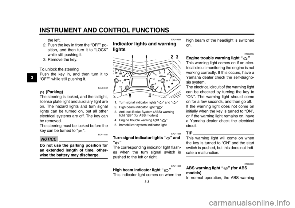
EAU49394
Indicator lights and warning
lights
EAU11031
Turn signal indicator lights “ ” and
“”
The corresponding indicator light flash-
es when the turn signal switch is
pushed to the left or right.
EAU11081
High beam indicator light “ ”
This indicator light comes on when the high beam of the headlight is switched
on.
EAU43024
Engine trouble warning light “ ”
This warning light comes on if an elec-
trical circuit monitoring the engine is not
working correctly. If this occurs, have a
Yamaha dealer check the self-diagno-
sis system.
The electrical circui
t of the warning light
can be checked by turning the key to
“ON”. The warning light should come
on for a few seconds, and then go off.
If the warning light does not come on
initially when the key is turned to “ON”,
or if the warning light remains on, have
a Yamaha dealer check the electrical
circuit.TIPThis warning light will come on when
the key is turned to “ON” and the start
switch is pushed, but this does not indi-cate a malfunction.
EAU53991
ABS warning light “ ” (for ABS
models)
In normal operation, the ABS warning
1. Turn signal indicator lights “ ” and “ ”
2. High beam indicator light “ ”
3. Anti-lock Brake System (ABS) warning light “ ” (for ABS models)
4. Engine trouble warning light “ ”
5. Immobilizer system indicator light
1
541
1
2
3
ABS
ABS
59C-9-E2.book 3 ページ 2013年6月18日 火曜日 午後1時33分
Page 28 of 100
INSTRUMENT AND CONTROL FUNCTIONS
3-13
1
23
4
5
6
7
8
9position. To cancel the turn signal
lights, push the switch in after it has re-
turned to the center position.
EAU12501
Horn switch “ ”
Press this switch to sound the horn.
EAU12661
Engine stop switch “ / ”
Set this switch to “ ” before starting
the engine. Set this switch to “ ” to
stop the engine in case of an emergen-
cy, such as when the vehicle overturns
or when the throttle cable is stuck.
EAU12722
Start switch “ ”
With the sidestand up, push this switch
while applying the front or rear brake to
crank the engine with the starter. See
page 5-1 for starting instructions prior
to starting the engine.
EAU44712
The engine trouble warning light and
ABS warning light (ABS model only)
may come on when the key is turned to
“ON” and the start switch is pushed, but this does not indicate a malfunction.
EAU12734
Hazard switch “ ”
With the key in the “ON” or “ ” posi-
tion, use this switch to turn on the haz-
ard lights (simultaneous flashing of all
turn signal lights).
The hazard lights are used in case of
an emergency or to warn other drivers
when your vehicle is stopped where it
might be a traffic hazard.NOTICE
ECA10062
Do not use the hazard lights for an
extended length of time with the en-
gine not running, otherwise the bat-tery may discharge.
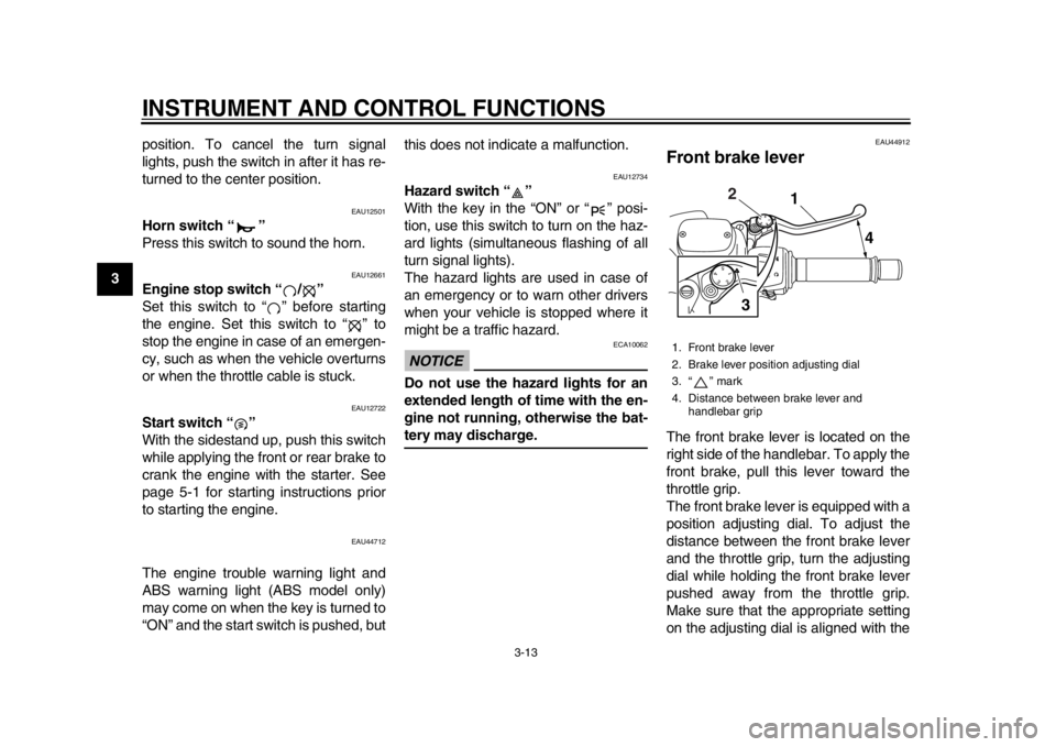
EAU44912
Front brake leverThe front brake lever is located on the
right side of the handlebar. To apply the
front brake, pull this lever toward the
throttle grip.
The front brake lever is equipped with a
position adjusting dial. To adjust the
distance between the front brake lever
and the throttle grip, turn the adjusting
dial while holding the front brake lever
pushed away from the throttle grip.
Make sure that the appropriate setting
on the adjusting dial is aligned with the1. Front brake lever
2. Brake lever position adjusting dial
3. “ ” mark
4. Distance between brake lever and
handlebar grip
1
4
2
3
59C-9-E2.book 13 ページ 2013年6月18日 火曜日 午後1時33分
Page 32 of 100
INSTRUMENT AND CONTROL FUNCTIONS
3-17
1
23
4
5
6
7
8
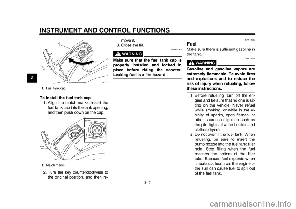
9To install the fuel tank cap
1. Align the match marks, insert the fuel tank cap into the tank opening,
and then push down on the cap.
2. Turn the key counterclockwise to the original position, and then re- move it.
3. Close the lid.
WARNING
EWA11262
Make sure that the fuel tank cap is
properly installed and locked in
place before riding the scooter.Leaking fuel is a fire hazard.
EAU13222
FuelMake sure there is sufficient gasoline in
the tank.
WARNING
EWA10882
Gasoline and gasoline vapors are
extremely flammable. To avoid fires
and explosions and to reduce the
risk of injury when refueling, followthese instructions.
1. Before refueling, turn off the en- gine and be sure that no one is sit-
ting on the vehicle. Never refuel
while smoking, or while in the vi-
cinity of sparks, open flames, or
other sources of ignition such as
the pilot lights of water heaters and
clothes dryers.
2. Do not overfill the fuel tank. When refueling, be sure to insert the
pump nozzle into the fuel tank filler
hole. Stop filling when the fuel
reaches the bottom of the filler
tube. Because fuel expands when
it heats up, heat from the engine or
the sun can cause fuel to spill out
of the fuel tank.
1. Fuel tank cap
1. Match marks
1
1
59C-9-E2.book 17 ページ 2013年6月18日 火曜日 午後1時33分
Page 44 of 100

FOR YOUR SAFETY – PRE-OPERATION CHECKS
4-2
1
2
34
5
6
7
8
9
Rear brake Check operation.
If soft or spongy, have Yamaha dealer bleed hydraulic system.
Check brake pads for wear.
Replace if necessary.
Check fluid level in reservoir.
If necessary, add specified brake fluid to specified level.
Check hydraulic system for leakage. 6-20, 6-22, 6-23
Throttle grip Make sure that operation is smooth.
Check throttle grip free play.
If necessary, have Yamaha dealer adjust throttle grip free play and lubricate cable
and grip housing. 6-17, 6-25
Wheels and tires Check for damage.
Check tire condition and tread depth.
Check air pressure.
Correct if necessary. 6-17, 6-19
Brake levers Make sure that operation is smooth.
Lubricate lever pivoting points if necessary. 6-25
Centerstand, sidestand Make sure that operation is smooth.
Lubricate pivots if necessary. 6-26
Chassis fasteners Make sure that all nuts, bolts
and screws are properly tightened.
Tighten if necessary. —
Instruments, lights, signals
and switches Check operation.
Correct if necessary.
—
Sidestand switch Check operation of ignition circuit cut-off system.
If system is not working correctly, have Yamaha dealer check vehicle. 3-26
ITEM CHECKS PAGE
59C-9-E2.book 2 ページ 2013年6月18日 火曜日 午後1時33分
Page 48 of 100
OPERATION AND IMPORTANT RIDING POINTS
5-4
1
2
3
45
6
7
8
9
EAU16821
Tips for reducing fuel
consumptionFuel consumption depends largely on
your riding style. Consider the following
tips to reduce fuel consumption:
Avoid high engine speeds during
acceleration.
Avoid high engine speeds with no
load on the engine.
Turn the engine off instead of let-
ting it idle for an extended length of
time (e.g., in traffic jams, at traffic
lights or at railroad crossings).
EAU16842
Engine break-inThere is never a more important period
in the life of your engine than the period
between 0 and 1600 km (1000 mi). For
this reason, you should read the follow-
ing material carefully.
Since the engine is brand new, do not
put an excessive load on it for the first
1600 km (1000 mi). The various parts in
the engine wear and polish themselves
to the correct operating clearances.
During this period, prolonged full-throt-
tle operation or any condition that might
result in engine overheating must be
avoided.
EAU36532
0–1000 km (0–600 mi)
Avoid prolonged operation above 4100
r/min. NOTICE: After 1000 km (600
mi) of operation, the engine oil must
be changed, and the oil filter car-
tridge or element replaced.
[ECA11283]
1000–1600 km (600–1000 mi)
Avoid prolonged operation above 5000
r/min. 1600 km (1000 mi) and beyond
The vehicle can now be operated nor-
mally.
NOTICE
ECA10311
Keep the engine speed out of
the tachometer red zone.
If any engine trouble should oc-
cur during the engine break-in
period, immediately have a
Yamaha dealer check the vehi-cle.
59C-9-E2.book 4 ページ 2013年6月18日 火曜日 午後1時33分
Page 55 of 100

PERIODIC MAINTENANCE AND ADJUSTMENT
6-6
2
3
4
567
8
9
24*Cooling system Check coolant level and vehicle
for coolant leakage.
Change coolant. Every 3 years
25 *V- b e l t Replace. When the V-belt replacement indicator flashes [every 20000 km (12500 mi)]
26 *Front and rear brake
switches Check operation.
27 Moving parts and
cables Lubricate.
28 *Throttle grip Check operation.
Check throttle grip free play, and
adjust if necessary.
Lubricate cable and grip housing.
29 *Lights, signals and
switches Check operation.
Adjust headlight beam.
NO. ITEM CHECK OR MAINTENANCE JOB
ODOMETER READING
ANNUAL
CHECK
1000 km
(600 mi) 10000 km
(6000 mi) 20000 km
(12000 mi) 30000 km
(18000 mi) 40000 km
(24000 mi)
59C-9-E2.book 6 ページ 2013年6月18日 火曜日 午後1時33分
Page 84 of 100

PERIODIC MAINTENANCE AND ADJUSTMENT
6-35
1
2
3
4
56
7
8
9
EAU52051
Replacing an auxiliary light
bulb1. Remove panel A. (See page 6-8.)
2. Remove the auxiliary light socket
(together with the bulb) by pulling it
out.
3. Remove the burnt-out bulb by pull- ing it out. 4. Insert a new bulb into the socket.
5. Install the auxiliary light socket (to-
gether with the bulb) by pushing it
in.
6. Install the panel.
EAU25882
TroubleshootingAlthough Yamaha scooters receive a
thorough inspection before shipment
from the factory, trouble may occur dur-
ing operation. Any problem in the fuel,
compression, or ignition systems, for
example, can cause poor starting and
loss of power.
The following troubleshooting charts
represent quick and easy procedures
for checking these vital systems your-
self. However, should your scooter re-
quire any repair, take it to a Yamaha
dealer, whose skilled technicians have
the necessary tools, experience, and
know-how to service the scooter prop-
erly.
Use only genuine Yamaha replace-
ment parts. Imitation parts may look like
Yamaha parts, but they are often inferi-
or, have a shorter service life and can
lead to expensive repair bills.
WARNING
EWA15142
When checking the fuel system, do
not smoke, and make sure there are
no open flames or sparks in the ar-
ea, including pilot lights from water
1. Auxiliary light bulb socket1
1. Auxiliary light bulb
2. Auxiliary light bulb socket
1 2
59C-9-E2.book 35 ページ 2013年6月18日 火曜日 午後1時33分
Page 89 of 100
SCOOTER CARE AND STORAGE
7-2
2
3
4
5
678
9
plenty of water, as it is harmful
to plastic parts.
Do not use any harsh chemical
products on plastic parts. Be
sure to avoid using cloths or
sponges which have been in
contact with strong or abrasive
cleaning products, solvent or
thinner, fuel (gasoline), rust re-
movers or inhibitors, brake flu-
id, antifreeze or electrolyte.
Do not use high-pressure wash-
ers or steam-jet cleaners since
they cause water seepage and
deterioration in the following ar-
eas: seals (of wheel and swing-
arm bearings, fork and brakes),
electric components (couplers,
connectors, instruments,
switches and lights), breather
hoses and vents.
For scooters equipped with a
windshield: Do not use strong
cleaners or hard sponges as
they will cause dulling or
scratching. Some cleaning com-
pounds for plastic may leave
scratches on the windshield.
Test the product on a small hid- den part of the windshield to
make sure that it does not leave
any marks. If the windshield is
scratched, use a quality plastic
polishing compound after
washing.
After normal use
Remove dirt with warm water, a mild
detergent, and a soft, clean sponge,
and then rinse thoroughly with clean
water. Use a toothbrush or bottlebrush
for hard-to-reach areas. Stubborn dirt
and insects will come off more easily if
the area is covered with a wet cloth for
a few minutes before cleaning.
After riding in the rain, near the sea oron salt-sprayed roadsSince sea salt or salt sprayed on roads
during winter are extremely corrosive in
combination with water, carry out the
following steps after each ride in the
rain, near the sea or on salt-sprayed
roads.TIPSalt sprayed on roads in the winter may
remain well into spring. 1. Clean the scooter with cold water and a mild detergent after the en-
gine has cooled down. NOTICE:
Do not use warm water since it
increases the corrosive action
of the salt.
[ECA10792]
2. Apply a corrosion protection spray on all metal, including chrome- and
nickel-plated, surfaces to prevent
corrosion.
After cleaning 1. Dry the scooter with a chamois or an absorbing cloth.
2. Use a chrome polish to shine chrome, aluminum and stain-
less-steel parts, including the ex-
haust system. (Even the thermally
induced discoloring of stain-
less-steel exhaust systems can be
removed through polishing.)
3. To prevent corrosion, it is recom- mended to apply a corrosion pro-
tection spray on all metal,
including chrome- and nickel-plat-
ed, surfaces.
4. Use spray oil as a universal clean-
59C-9-E2.book 2 ページ 2013年6月18日 火曜日 午後1時33分