YAMAHA TRACER 7 2022 Owner's Manual
Manufacturer: YAMAHA, Model Year: 2022, Model line: TRACER 7, Model: YAMAHA TRACER 7 2022Pages: 100, PDF Size: 3.93 MB
Page 21 of 100
Instrument and control functions
3-4
3
lig
ht remains on after addin g oil,
stop the en gine an d have a Yamaha
d ealer check the vehicle.
EAU11449
Coolant temperature warnin g
lig ht “ ”
This warning light comes on when the
engine is overheating. If this occurs,
stop the engine immediately and allow
the engine to cool. (See page 6-36.)
For vehicles with a radiator fan, the ra-
diator fan(s) automatically switch on or
off according to the coolant tempera-
ture.TIPWhen the vehicle is turned on, the light
will come on for a few seconds, and
then go off. If the light does not come
on, or if the light remains on, have a
Yamaha dealer check the vehicle. NOTICE
ECA10022
Do not continue to operate the en-
g ine if it is overheatin g.
EAU91840
Malfunction in dicator li ght
(MIL) “ ”
This light comes on or flashes if a prob-
lem is detected in the engine or other
vehicle control system. If this occurs,
have a Yamaha dealer check the on-
board diagnostic system. The electri-
cal circuit of the warning light can be
checked by turning the vehicle power
on. The light should come on for a few
seconds, and then go off. If the light
does not come on initially when the ve-
hicle power is turned on, or if the light
remains on, have a Yamaha dealer
check the vehicle.NOTICE
ECA26820
If the MIL starts flashin g, re duce en-
g ine spee d to prevent exhaust sys-
tem damag e.TIPThe engine is sensitively monitored by
the on-board diagnostic system to de-
tect deterioration or malfunction of the
emission control system. Therefore the
MIL may come on or flash due to vehi-
cle modifications, lack of maintenance, or excessive/improper use of the mo-
torcycle. To prevent this, observe
these precautions.
Do not attempt to modify the soft-
ware of the engine control unit.
Do not add any electrical acces-
sories that interfere with engine
control.
Do not use aftermarket accesso-
ries or parts such as suspension,
spark plugs, injectors, exhaust
system, etc.
Do not change the drivetrain
specifications (chain, sprockets,
wheels, tires, etc.).
Do not remove or alter the O2 sen-
sor, air induction system, or ex-
haust parts (catalysts or EXUP,
etc.).
Maintain the drive chain properly.
Maintain correct tire pressure.
Maintain proper brake pedal
height to prevent rear brake from
dragging.
Do not operate the vehicle in an
extreme manner. For example, re-
peated or excessive opening and
UB4TEAE0.book Page 4 Tues day, October 26, 2021 4:00 PM
Page 22 of 100
Instrument and control functions
3-5
3 closing of the throttle, racing,
burnouts, wheelies, extended
half-clutch use, etc.
EAU69895
ABS warnin
g li ght “ ”
This warning light comes on when the
vehicle is first turned on, and goes off
after starting riding. If the warning light
comes on while riding, the anti-lock
brake system may not work correctly.
WARNING
EWA16043
If the ABS warnin g lig ht does not
turn off after reachin g 10 km/h (6
mi/h), or if the warnin g li ght comes
on while ri din g:
Use extra caution to avoi d pos-
si ble wheel lock d uring emer-
g ency brakin g.
Have a Yamaha dealer check
the vehicle as soon as possi ble.
EAUM3622
Immo bilizer system in dicator
li g ht “ ”
When the vehicle is turned off and 30
seconds have passed, the indicator
light will flash steadily to indicate the immobilizer system is enabled. After 24
hours have passed, the indicator light
will stop flashing, however the immobi-
lizer system is still enabled.
TIPWhen the vehicle is turned on, the light
will come on for a few seconds, and go
off. Otherwise, have a Yamaha dealer
check the vehicle.Trou
bleshootin g
If a problem is detected in the immobi-
lizer system, the light will flash in a pat-
tern. If the immobilizer system
indicator light flashes in the pattern,
slowly 5 times then quickly 2 times, this
could be caused by transponder inter-
ference. If this occurs, try the following. 1. Make sure there are no other im- mobilizer keys close to the main
switch. Other immobilizer system
keys may cause signal interfer-
ence and prevent the engine from
starting.
2. Use the code re-registering key to start the engine. 3. If the engine starts, turn it off, and
try starting the engine with the
standard keys.
4. If one or more of the standard keys do not start the engine, take
the vehicle and all keys to a
Yamaha dealer to have the stan-
dard keys re-registered.
ABS
UB4TEAE0.book Page 5 Tues day, October 26, 2021 4:00 PM
Page 23 of 100
Instrument and control functions
3-6
3
EAUM4251
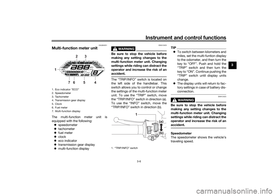
Multi-function meter unitThe multi-function meter unit is
equipped with the following:
speedometer
tachometer
fuel meter
clock
eco indicator
transmission gear display
multi-function display
WARNING
EWA12423
Be sure to stop the vehicle before
makin g any settin g chan ges to the
multi-function meter unit. Chan gin g
settin gs while ri din g can distract the
operator an d increase the risk of an
acci dent.The “TRIP/INFO” switch is located on
the left side of the handlebar. This
switch allows you to control or change
the settings of the multi-function meter
unit. To use the “TRIP” switch, move
the “TRIP/INFO” switch in direction (a).
To use the “INFO” switch, move the
“TRIP/INFO” switch in direction (b).
TIP To switch between kilometers and
miles, set the multi-funtion display
to the odometer, and then turn the
key to “OFF”. Push and hold the
“TRIP” switch and then turn the
key to “ON”. Continue pushing the
“TRIP” switch until display units
change.
The display units will return to fac-
tory settings in case of battery dis-
connection.
WARNING
EWA12423
Be sure to stop the vehicle before
makin g any settin g chan ges to the
multi-function meter unit. Chan gin g
settin gs while ri din g can d istract the
operator an d increase the risk of an
acci dent.Speed ometer
The speedometer shows the vehicle’s
traveling speed.
1. Eco indicator “ECO”
2. Speedometer
3. Tachometer
4. Transmission gear display
5. Clock
6. Fuel meter
7. Multi-function display
6
1 3
54
7
2
1. “TRIP/INFO” switch
1
UB4TEAE0.book Page 6 Tues day, October 26, 2021 4:00 PM
Page 24 of 100
Instrument and control functions
3-7
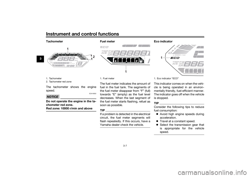
3 Tachometer
The tachometer shows the engine
speed.
NOTICE
ECA10032
Do not operate the en
gine in the ta-
chometer red zone.
Re d zone: 10000 r/min an d a bove
Fuel meter
The fuel meter indicates the amount of
fuel in the fuel tank. The segments of
the fuel meter disappear from “F” (full)
towards “E” (empty) as the fuel level
decreases. When the last segment of
the fuel meter starts flashing, refuel as
soon as possible.TIPIf a problem is detected in the electrical
circuit, the fuel meter segments will
flash repeatedly. If this occurs, have a
Yamaha dealer check the vehicle.
Eco in dicator
This indicator comes on when the vehi-
cle is being operated in an environ-
mentally friendly, fuel-efficient manner.
The indicator goes off when the vehicle
is stopped.TIPConsider the following tips to reduce
fuel consumption: Avoid high engine speeds during
acceleration.
Travel at a constant speed.
Select the transmission gear that
is appropriate for the vehicle
speed.
1. Tachometer
2. Tachometer red zone
1
2
1. Fuel meter
1
1. Eco indicator “ECO”
1
UB4TEAE0.book Page 7 Tues day, October 26, 2021 4:00 PM
Page 25 of 100
Instrument and control functions
3-8
3
Transmission
gear display
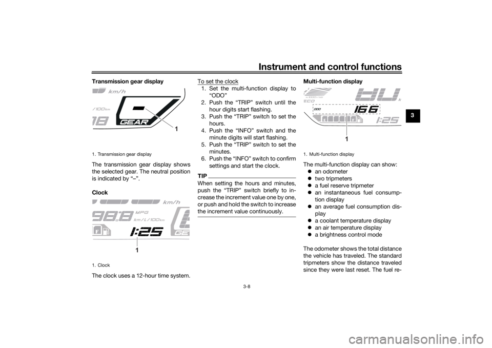
The transmission gear display shows
the selected gear. The neutral position
is indicated by “–”.
Clock
The clock uses a 12-hour time system. To set the clock
1. Set the multi-function display to
“ODO”
2. Push the “TRIP” switch until the hour digits start flashing.
3. Push the “TRIP” switch to set the hours.
4. Push the “INFO” switch and the minute digits will start flashing.
5. Push the “TRIP” switch to set the minutes.
6. Push the “INFO” switch to confirm settings and start the clock.TIPWhen setting the hours and minutes,
push the “TRIP” switch briefly to in-
crease the increment value one by one,
or push and hold the switch to increase
the increment value continuously.
Multi-function display
The multi-function display can show: an odometer
two tripmeters
a fuel reserve tripmeter
an instantaneous fuel consump-
tion display
an average fuel consumption dis-
play
a coolant temperature display
an air temperature display
a brightness control mode
The odometer shows the total distance
the vehicle has traveled. The standard
tripmeters show the distance traveled
since they were last reset. The fuel re-
1. Transmission gear display
1. Clock
1
1
1. Multi-function display
1
UB4TEAE0.book Page 8 Tues day, October 26, 2021 4:00 PM
Page 26 of 100
Instrument and control functions
3-9
3 serve tripmeter shows the distance
traveled since the last segment of the
fuel meter began flashing.
TIP
The odometer will lock at 999999
and cannot be reset.
The tripmeter will reset to 0 and
continue counting after 9999.9 is
reached.Push the “TRIP” switch briefly to
switch the display in the following or-
der:
ODO → TRIP 1 → TRIP 2 → TRIP F →
km/L or L/100 km or MPG → AVE_ _._
km/L or AVE_ _._ L/100 km or AVE_ _._
MPG → _ _ °C → Air_ _ °C → ODOTIP Push the “INFO” switch briefly to
switch the display in the reverse
order.
The display changes to fuel re-
serve tripmeter “TRIP F” when the
last segment of the fuel meter
starts flashing.
To reset a tripmeter, select it by
pushing the “TRIP” switch or the
“INFO” switch, and while the dig-
its are flashing, push the “INFO”
switch until it is reset.
If you do not reset the fuel reserve
tripmeter manually, it will reset au-
tomatically and disappear from
the display after refueling and
traveling 5 km (3 mi).
Fuel reserve tripmeter
When the fuel level becomes low, the
last segment of the fuel meter will start
flashing. The fuel reserve tripmeter
“TRIP F” will automatically appear and
start counting the distance traveled
from that point. In this case, push the
“TRIP” switch to switch the display in
the following order:
TRIP F → km/L or L/100 km → AVE_
_._ km/L or AVE_ _._ L/100 km → _ _
°C → Air_ _ °C → ODO → TRIP 1 →
TRIP 2 → TRIP F For the UK:
TRIP F
→ MPG → AVE_ _._ MPG → _
_ °C → Air_ _ °C → ODO → TRIP 1 →
TRIP 2 → TRIP F
TIPPush the “INFO” switch to change
the display in the reverse order.
You can manually reset the fuel re-
serve tripmeter, or after refueling
and traveling 5 km (3 mi) it will re-
set automatically and disappear
from the display.Instantaneous fuel consumption
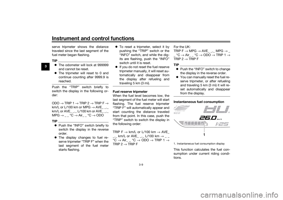
This function calculates the fuel con-
sumption under current riding condi-
tions.1. Instantaneous fuel consumption display
1
UB4TEAE0.book Page 9 Tues day, October 26, 2021 4:00 PM
Page 27 of 100
Instrument and control functions
3-10
3
The instantaneous fuel consumption
display can be set to either “km/L”,
“L/100 km” when using kilometers.
To switch the the fuel consumption
units, push the “TRIP” switch until the
measurement units change. When us-
ing miles, the fuel consumption unit is
“MPG”.
“km/L”: The distance that can be
traveled on 1.0 L of fuel under the
current riding conditions is shown.
“L/100 km”: The amount of fuel
necessary to travel 100 km under
the current riding conditions is
shown.
“MPG”: The distance that can be
traveled on 1.0 Imp.gal of fuel un-
der the current riding conditions is
shown.
To switch the instantaneous fuel con-
sumption settings, push and hold
“TRIP” switch until the display chang-
es.
TIPIf traveling at speeds under 20 km/h
(12 mi/h), “_ _._” is displayed.
Avera ge fuel consumption
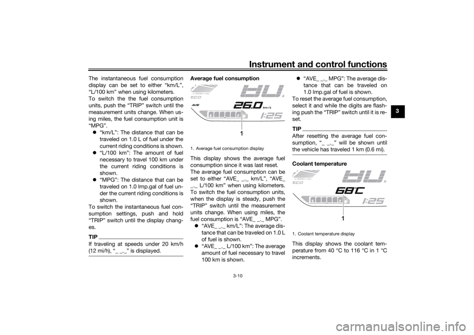
This display shows the average fuel
consumption since it was last reset.
The average fuel consumption can be
set to either “AVE_ _._ km/L”, “AVE_
_._ L/100 km” when using kilometers.
To switch the fuel consumption units,
when the display is steady, push the
“TRIP” switch until the measurement
units change. When using miles, the
fuel consumption is “AVE_ _._ MPG”. “AVE_ _._ km/L”: The average dis-
tance that can be traveled on 1.0 L
of fuel is shown.
“AVE_ _._ L/100 km”: The average
amount of fuel necessary to travel
100 km is shown.
“AVE_ _._ MPG”: The average dis-
tance that can be traveled on
1.0 Imp.gal of fuel is shown.
To reset the average fuel consumption,
select it and while the digits are flash-
ing push the “TRIP” switch until it is re-
set.
TIPAfter resetting the average fuel con-
sumption, “_ _._” will be shown until
the vehicle has traveled 1 km (0.6 mi).Coolant temperature
This display shows the coolant tem-
perature from 40 °C to 116 °C in 1 °C
increments.
1. Average fuel consumption display
1
1. Coolant temperature display
1
UB4TEAE0.book Page 10 Tuesday, October 26, 2021 4:00 PM
Page 28 of 100
Instrument and control functions
3-11
3 If the message “Hi” flashes, stop the
vehicle, then stop the engine, and let it
cool. (See page 6-36.)
TIP
When the coolant temperature is
below 40 °C, “Lo” will be dis-
played.
The coolant temperature varies
with changes in the weather and
engine load.Air temperature
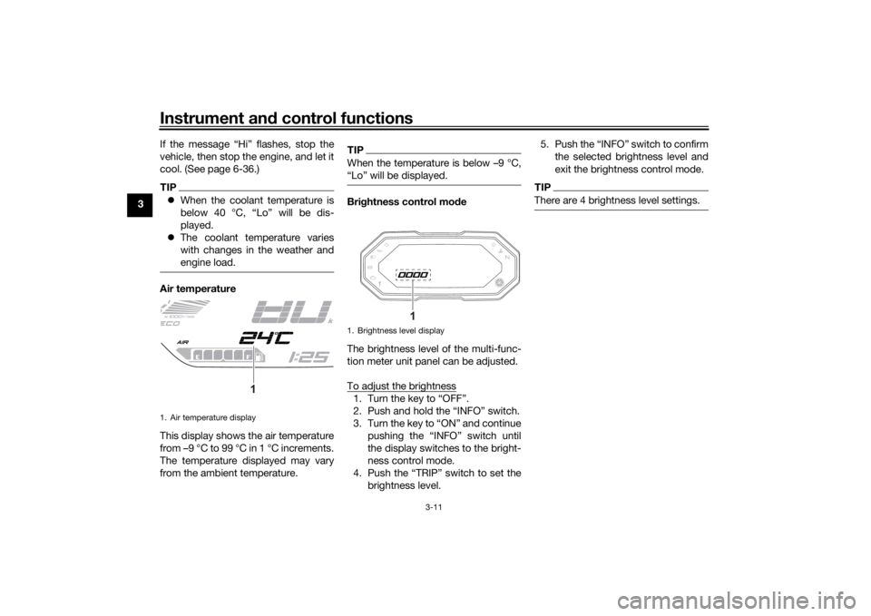
This display shows the air temperature
from –9 °C to 99 °C in 1 °C increments.
The temperature displayed may vary
from the ambient temperature.
TIPWhen the temperature is below –9 °C,
“Lo” will be displayed.Brig htness control mo de
The brightness level of the multi-func-
tion meter unit panel can be adjusted.
To adjust the brightness1. Turn the key to “OFF”.
2. Push and hold the “INFO” switch.
3. Turn the key to “ON” and continue pushing the “INFO” switch until
the display switches to the bright-
ness control mode.
4. Push the “TRIP” switch to set the brightness level. 5. Push the “INFO” switch to confirm
the selected brightness level and
exit the brightness control mode.
TIPThere are 4 brightness level settings.
1. Air temperature display
1
1. Brightness level display
1
UB4TEAE0.book Page 11 Tuesday, October 26, 2021 4:00 PM
Page 29 of 100
Instrument and control functions
3-12
3
EAU1234R
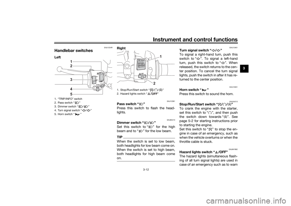
Han dle bar switchesLeft Ri
ght
EAU12381
Pass switch “ ”
Press this switch to flash the head-
lights.
EAU85410
Dimmer switch “ / ”
Set this switch to “ ” for the high
beam and to “ ” for the low beam.TIPWhen the switch is set to low beam,
both headlights for low beam come on.
When the switch is set to high beam,
both headlights for high beam come
on.
EAU12461
Turn si gnal switch “ / ”
To signal a right-hand turn, push this
switch to “ ”. To signal a left-hand
turn, push this switch to “ ”. When
released, the switch returns to the cen-
ter position. To cancel the turn signal
lights, push the switch in after it has re-
turned to the center position.
EAU12501
Horn switch “ ”
Press this switch to sound the horn.
EAU54213
Stop/Run/Start switch “ / / ”
To crank the engine with the starter,
set this switch to “ ”, and then push
the switch down towards “ ”. See
page 5-2 for starting instructions prior
to starting the engine.
Set this switch to “ ” to stop the en-
gine in case of an emergency, such as
when the vehicle overturns or when the
throttle cable is stuck.
EAUM1992
Hazar d lig hts switch “ /OFF”
The hazard lights (simultaneous flash-
ing of all turn signal lights) are used in
case of an emergency such as to warn
1. “TRIP/INFO” switch
2. Pass switch “ ”
3. Dimmer switch “ / ”
4. Turn signal switch “ / ”
5. Horn switch “ ”
34521
1. Stop/Run/Start switch “ / / ”
2. Hazard lights switch “ ”
1
2/
UB4TEAE0.book Page 12 Tuesday, October 26, 2021 4:00 PM
Page 30 of 100
Instrument and control functions
3-13
3 other drivers when your vehicle is
stopped where it might be a traffic haz-
ard.
With the main switch in the on position,
set the hazard lights switch to “ ” to
turn on the hazard lights. The main
switch can then be turned to the off po-
sition or lock position, however the
hazard lights will continue flash. To
turn off the hazard lighs, turn the main
switch to the on position and set this
switch to “OFF”.
NOTICE
ECA10062
Do not use the hazard
lights for an
exten ded len gth of time with the en-
g ine not runnin g, otherwise the bat-
tery may dischar ge.
EAUM3720
Trip/info switch “TRIP/INFO”
This switch is used to make setting and
display changes in the multi-function
meter unit. See page 3-6 for more in-
formation.
EAU12823
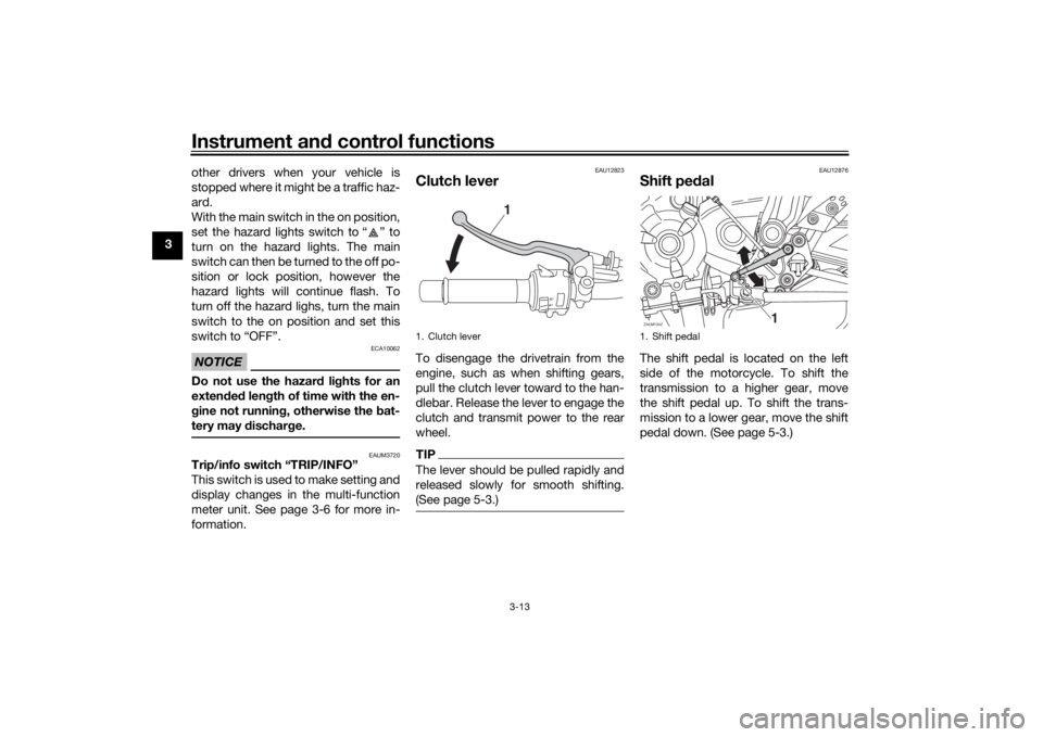
Clutch leverTo disengage the drivetrain from the
engine, such as when shifting gears,
pull the clutch lever toward to the han-
dlebar. Release the lever to engage the
clutch and transmit power to the rear
wheel.TIPThe lever should be pulled rapidly and
released slowly for smooth shifting.
(See page 5-3.)
EAU12876
Shift pe dalThe shift pedal is located on the left
side of the motorcycle. To shift the
transmission to a higher gear, move
the shift pedal up. To shift the trans-
mission to a lower gear, move the shift
pedal down. (See page 5-3.)
1. Clutch lever
1
1. Shift pedalZAUM1342
1
UB4TEAE0.book Page 13 Tuesday, October 26, 2021 4:00 PM