YAMAHA TRACER 900 GT 2018 Owner's Guide
Manufacturer: YAMAHA, Model Year: 2018, Model line: TRACER 900 GT, Model: YAMAHA TRACER 900 GT 2018Pages: 120, PDF Size: 9.6 MB
Page 31 of 120
Instrument and control functions
3-16
3
TIP The MENU screen can be ac-
cessed by long pushing the wheel
switch, except when the grip
warmer display is selected or the
fuel tripmeter (F-TRIP) is dis-
played.
Should vehicle motion be detect-
ed, the screen will automatically
exit MENU and change to the
main screen.“Maintenance”
This module allows you to record dis-
tance traveled between engine oil
changes (use the OIL item), and for two
other items of your choice (use INTER-
VAL 1 and INTERVAL 2).
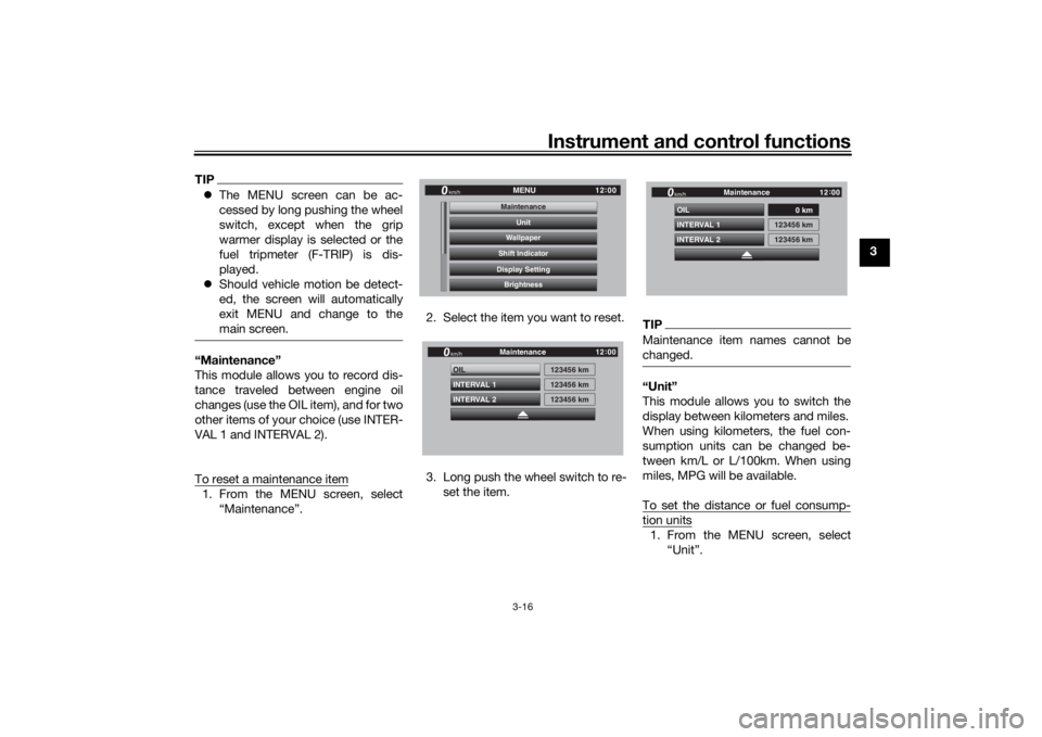
To reset a maintenance item1. From the MENU screen, select
“Maintenance”. 2. Select the item you want to reset.
3. Long push the wheel switch to re-
set the item.
TIPMaintenance item names cannot be
changed.“Unit”
This module allows you to switch the
display between kilometers and miles.
When using kilometers, the fuel con-
sumption units can be changed be-
tween km/L or L/100km. When using
miles, MPG will be available.
To set the distance or fuel consump-tion units1. From the MENU screen, select“Unit”.
12:
00
MENU
km/h
BrightnessDisplay SettingShift IndicatorWallpaperUnit
MaintenanceMaintenance
INTERVAL 2 OIL
INTERVAL 1
123456 km123456 km
123456 km
Maintenance
km/h
GPS
12 :
00
INTERVAL 2 OIL
INTERVAL 1
0 km
123456 km
123456 km
Maintenance
km/h
GPS
12 :
00
UB1JE0E0.book Page 16 Tuesday, February 13, 2018 9:12 AM
Page 32 of 120
Instrument and control functions
3-17
3
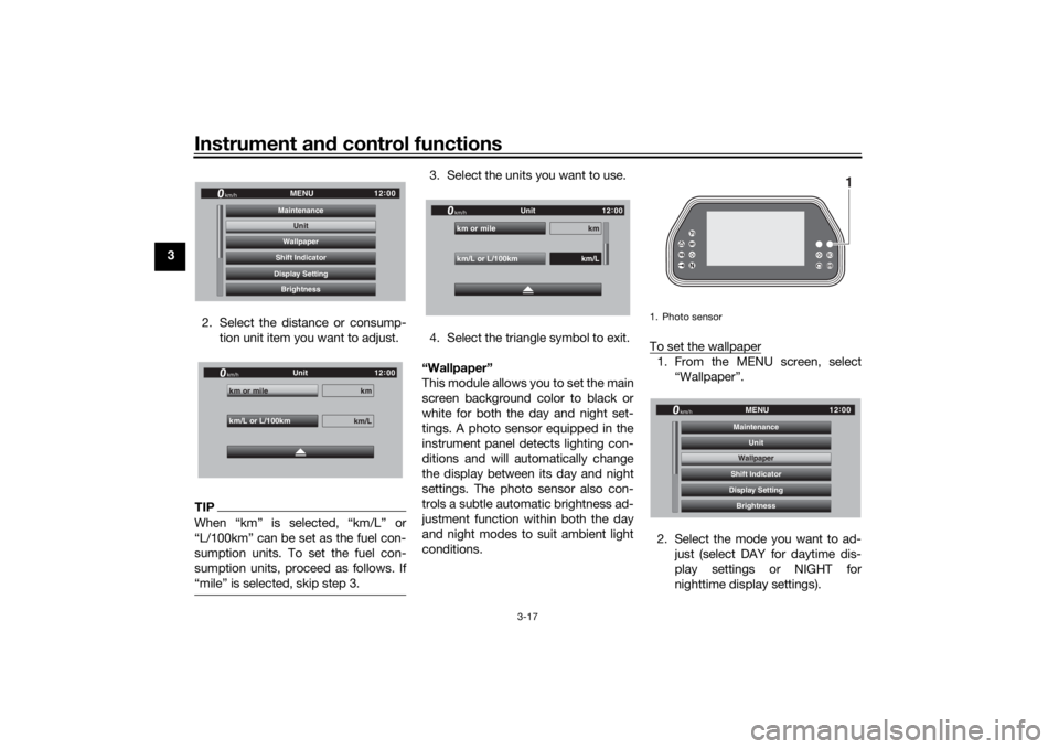
2. Select the distance or consump-tion unit item you want to adjust.
TIPWhen “km” is selected, “km/L” or
“L/100km” can be set as the fuel con-
sumption units. To set the fuel con-
sumption units, proceed as follows. If
“mile” is selected, skip step 3.
3. Select the units you want to use.
4. Select the triangle symbol to exit.
“Wallpaper”
This module allows you to set the main
screen background color to black or
white for both the day and night set-
tings. A photo sensor equipped in the
instrument panel detects lighting con-
ditions and will automatically change
the display between its day and night
settings. The photo sensor also con-
trols a subtle automatic brightness ad-
justment function within both the day
and night modes to suit ambient light
conditions. To set the wallpaper
1. From the MENU screen, select
“Wallpaper”.
2. Select the mode you want to ad- just (select DAY for daytime dis-
play settings or NIGHT for
nighttime display settings).
12:
00
MENU
km/h
BrightnessDisplay SettingShift IndicatorWallpaperUnit
Maintenance
Unit
km/L or L/100km km or mile
km
km/L
Unit
km/h
GPS
12 :
00
km/L or L/100km km or mile
km
km/L
Unit
km/h
GPS
12 :
00
1. Photo sensor
1
12 :
00
MENU
km/h
BrightnessDisplay SettingShift IndicatorWallpaperUnit
MaintenanceWallpaper
UB1JE0E0.book Page 17 Tuesday, February 13, 2018 9:12 AM
Page 33 of 120
Instrument and control functions
3-18
3
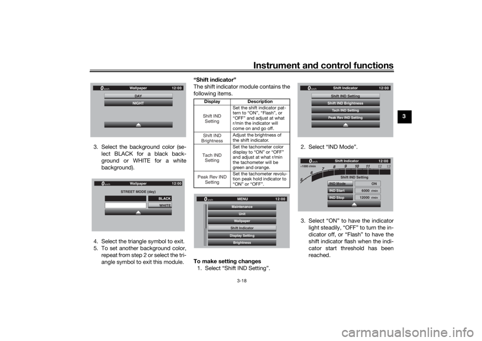
3. Select the background color (se- lect BLACK for a black back-
ground or WHITE for a white
background).
4. Select the triangle symbol to exit.
5. To set another background color, repeat from step 2 or select the tri-
angle symbol to exit this module. “Shift in
dicator”
The shift indicator module contains the
following items.
To make settin g chan ges
1. Select “Shift IND Setting”. 2. Select “IND Mode”.
3. Select “ON” to have the indicator
light steadily, “OFF” to turn the in-
dicator off, or “Flash” to have the
shift indicator flash when the indi-
cator start threshold has been
reached.
12:
00
Wallpaper
km/h
DAYNIGHT
STREET MODE (day)
WHITE
Wallpaper
km/h
GPS
12 :
00
BLACK
Display Description
Set the shift indicator pat-
tern to “ON”, “Flash”, or
“OFF” and adjust at what
r/min the indicator will
come on and go off.
Adjust the brightness of
the shift indicator.
Set the tachometer color
display to “ON” or “OFF”
and adjust at what r/min
the tachometer will be
green and orange.
Set the tachometer revolu-
tion peak hold indicator to
“ON” or “OFF”.Shift IND SettingShift IND
BrightnessTach IND SettingPeak Rev IND Setting
12:
00
MENU
km/h
BrightnessDisplay SettingShift IndicatorWallpaperUnit
MaintenanceShift Indicator
12 :
00
Shift Indicator
km/h
Tach IND SettingShift IND SettingPeak Rev IND SettingShift IND Brightness
1000 r/min
12 :
00
Shift IND Setting
IND Mode
IND Start
IND Stop ON
6000
r/min
12000
r/min
km/h
Shift Indicator
UB1JE0E0.book Page 18 Tuesday, February 13, 2018 9:12 AM
Page 34 of 120
Instrument and control functions
3-19
3
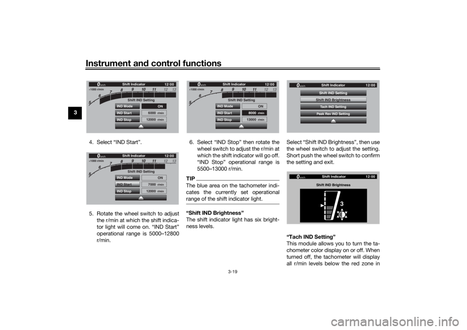
4. Select “IND Start”.
5. Rotate the wheel switch to adjustthe r/min at which the shift indica-
tor light will come on. “IND Start”
operational range is 5000–12800
r/min. 6. Select “IND Stop” then rotate the
wheel switch to adjust the r/min at
which the shift indicator will go off.
“IND Stop” operational range is
5500–13000 r/min.
TIPThe blue area on the tachometer indi-
cates the currently set operational
range of the shift indicator light.“Shift IND Bri ghtness”
The shift indicator light has six bright-
ness levels. Select “Shift IND Brightness”, then use
the wheel switch to adjust the setting.
Short push the wheel switch to confirm
the setting and exit.
“Tach IND Settin
g”
This module allows you to turn the ta-
chometer color display on or off. When
turned off, the tachometer will display
all r/min levels below the red zone in
1000 r/min
12 :
00
Shift IND Setting
IND Mode
IND Start
IND Stop ON
6000
r/min
12000
r/min
km/h
Shift Indicator
1000 r/min
12 :
00
Shift IND Setting
IND Mode
IND Start
IND Stop ON
7000
r/min
12000
r/min
km/h
Shift Indicator
1000 r/min
12 :
00
Shift IND Setting
IND Mode
IND Start
IND Stop ON
8000
r/min
13000
r/min
km/h
Shift Indicator
12 :
00
Shift Indicator
km/h
Tach IND SettingShift IND SettingPeak Rev IND SettingShift IND Brightness
12 :
00
Shift Indicator
km/h
Shift IND Bri ghtness
3
UB1JE0E0.book Page 19 Tuesday, February 13, 2018 9:12 AM
Page 35 of 120
Instrument and control functions
3-20
3
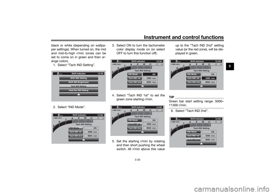
black or white (depending on wallpa-
per settings). When turned on, the mid
and mid-to-high r/min zones can be
set to come on in green and then or-
ange colors.
1. Select “Tach IND Setting”.
2. Select “IND Mode”. 3. Select ON to turn the tachometer
color display mode on (or select
OFF to turn this function off).
4. Select “Tach IND 1st” to set the green zone starting r/min.
5. Set the starting r/min by rotating and then short pushing the wheel
switch. All r/min above this value up to the “Tach IND 2nd” setting
value (or the red zone), will be dis-
played in green.
TIPGreen bar start setting range: 5000–
11300 r/min.6. Select “Tach IND 2nd”.
12
:
00
Shift Indicator
km/h
Tach IND SettingShift IND SettingPeak Rev IND SettingShift IND Brightness
1000 r/min
12 :
00
km/h
Shift Indicator
Tach IND Setting
IND Mode ON
5000
r/min
8000
r/min
Tach IND 1st
Tach IND 2nd
1000 r/min
12 :
00
km/h
Shift Indicator
Tach IND Setting
IND Mode
ON
5000
r/min
8000
r/min
Tach IND 1st
Tach IND 2nd
1000 r/min
12 :
00
km/h
Shift Indicator
Tach IND Setting
IND Mode ON
5000
r/min
8000
r/min
Tach IND 1st
Tach IND 2nd
1000 r/min
12 :
00
km/h
Shift Indicator
Tach IND Setting
IND Mode ON
5000
r/min
8000
r/min
Tach IND 1st
Tach IND 2nd
1000 r/min
12 :
00
km/h
Shift Indicator
Tach IND Setting
IND Mode ON
5000
r/min
8000
r/min
Tach IND 1st
Tach IND 2nd
UB1JE0E0.book Page 20 Tuesday, February 13, 2018 9:12 AM
Page 36 of 120
Instrument and control functions
3-21
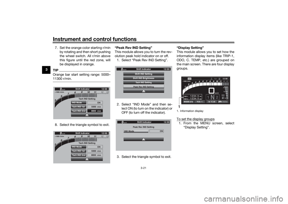
3 7. Set the orange color starting r/min
by rotating and then short pushing
the wheel switch. All r/min above
this figure until the red zone, will
be displayed in orange.
TIPOrange bar start setting range: 5000–
11300 r/min.8. Select the triangle symbol to exit. “Peak Rev IND Settin
g”
This module allows you to turn the rev-
olution peak hold indicator on or off. 1. Select “Peak Rev IND Setting”.
2. Select “IND Mode” and then se- lect ON (to turn on the indicator) or
OFF (to turn off the indicator).
3. Select the triangle symbol to exit. “Display Setting
”
This module allows you to set how the
information display items (like TRIP-1,
ODO, C. TEMP, etc.) are grouped on
the main screen. There are four display
groups.
To set the display groups
1. From the MENU screen, select “Display Setting”.
1000 r/min
12:
00
km/h
Shift Indicator
Tach IND Setting
IND Mode ON
5000
r/min
8000
r/min
Tach IND 1st
Tach IND 2nd
1000 r/min
12 :
00
km/h
Shift Indicator
Tach IND Setting
IND Mode ON
5000
r/min
8000
r/min
Tach IND 1st
Tach IND 2nd
12 :
00
Shift Indicator
km/h
Tach IND SettingShift IND SettingPeak Rev IND SettingShift IND BrightnessPeak Rev IND Setting
IND Mode
ON
Shift Indicator
km/h
GPS
12 :
00
1. Information display
km
TRIP-2
TRIP-1
1234.5 1234.5
km
1N
2km/h
1000 r/min
QS
12
:
00 EECOF2/1
MODE-
STD
TCS 1
In °C 25
1
UB1JE0E0.book Page 21 Tuesday, February 13, 2018 9:12 AM
Page 37 of 120
Instrument and control functions
3-22
3
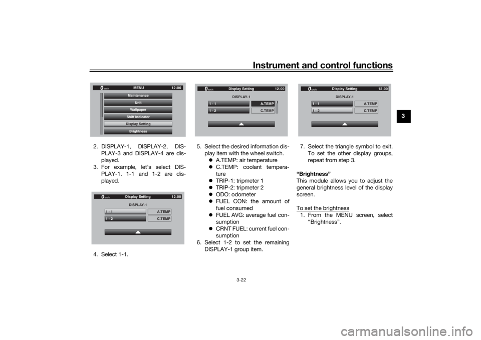
2. DISPLAY-1, DISPLAY-2, DIS- PLAY-3 and DISPLAY-4 are dis-
played.
3. For example, let’s select DIS- PLAY-1. 1-1 and 1-2 are dis-
played.
4. Select 1-1. 5. Select the desired information dis-
play item with the wheel switch. A.TEMP: air temperature
C.TEMP: coolant tempera-
ture
TRIP-1: tripmeter 1
TRIP-2: tripmeter 2
ODO: odometer
FUEL CON: the amount of
fuel consumed
FUEL AVG: average fuel con-
sumption
CRNT FUEL: current fuel con-
sumption
6. Select 1-2 to set the remaining DISPLAY-1 group item. 7. Select the triangle symbol to exit.
To set the other display groups,
repeat from step 3.
“Brig htness”
This module allows you to adjust the
general brightness level of the display
screen.
To set the brightness
1. From the MENU screen, select “Brightness”.
12:
00
MENU
km/h
BrightnessDisplay SettingShift IndicatorWallpaperUnit
MaintenanceDisplay SettingDISPLAY-1
1 - 1
A.TEMP
1 - 2
C.TEMP
Display Setting
km/h
GPS
12 :
00
DISPLAY-1
1 - 1
A.TEMP
1 - 2
C.TEMP
Display Setting
km/h
GPS
12 :
00
DISPLAY-1
1 - 1
A.TEMP
1 - 2
C.TEMP
Display Setting
km/h
GPS
12 :
00
UB1JE0E0.book Page 22 Tuesday, February 13, 2018 9:12 AM
Page 38 of 120
Instrument and control functions
3-23
3
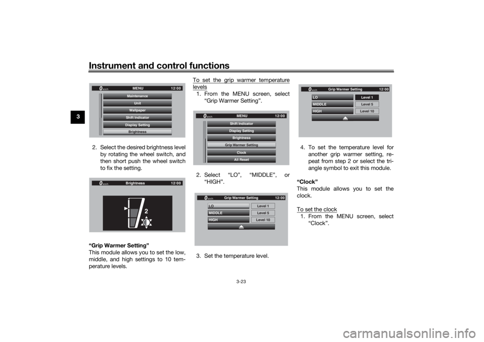
2. Select the desired brightness levelby rotating the wheel switch, and
then short push the wheel switch
to fix the setting.
“Grip Warmer Settin g”
This module allows you to set the low,
middle, and high settings to 10 tem-
perature levels. To set the grip warmer temperature
levels1. From the MENU screen, select
“Grip Warmer Setting”.
2. Select “LO”, “MIDDLE”, or “HIGH”.
3. Set the temperature level. 4. To set the temperature level for
another grip warmer setting, re-
peat from step 2 or select the tri-
angle symbol to exit this module.
“Clock”
This module allows you to set the
clock.
To set the clock
1. From the MENU screen, select “Clock”.
12:
00
MENU
km/h
BrightnessDisplay SettingShift IndicatorWallpaperUnit
MaintenanceBrightness
12 :
00
km/h
Brightness
2
12 :
00
MENU
km/h
All ResetClock
Grip Warmer Setting
BrightnessDisplay SettingShift IndicatorGrip Warmer Setting
HIGH LO
MIDDLE
Level 5Level 1
Level 10
km/h
GPS
12 :
00
Grip Warmer Setting
HIGH LO
MIDDLEkm/h
GPS
12 :
00
Level 5 Level 1
Level 10
Grip Warmer Setting
UB1JE0E0.book Page 23 Tuesday, February 13, 2018 9:12 AM
Page 39 of 120
Instrument and control functions
3-24
3
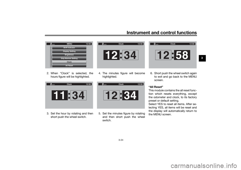
2. When “Clock” is selected, the hours figure will be highlighted.
3. Set the hour by rotating and then short push the wheel switch. 4. The minutes figure will become
highlighted.
5. Set the minutes figure by rotating and then short push the wheel
switch. 6. Short push the wheel switch again
to exit and go back to the MENU
screen.
“All Reset”
This module contains the all reset func-
tion which resets everything, except
the odometer and clock, to its factory
preset or default setting.
Select YES to reset all items. After se-
lecting YES, all items will be reset and
the display will automatically return to
the MENU screen.
12 :
00
MENU
km/h
All ResetClock
Grip Warmer Setting
BrightnessDisplay SettingShift Indicator
Clock
12 :
00
Clock
km/h11 34
:
12 :
00
Clock
km/h12 34
:
12 :
00
Clock
km/h12 34
:
12 :
00
Clock
km/h12 58
:
UB1JE0E0.book Page 24 Tuesday, February 13, 2018 9:12 AM
Page 40 of 120
Instrument and control functions
3-25
3
EAU84420
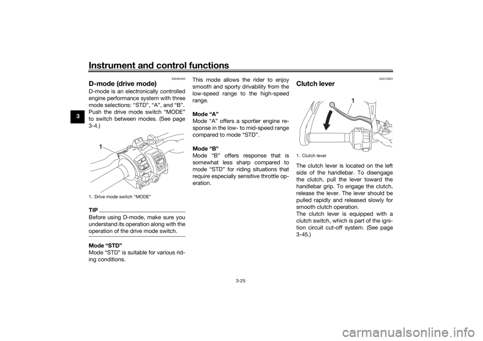
D-mo de ( drive mo de)D-mode is an electronically controlled
engine performance system with three
mode selections: “STD”, “A”, and “B”.
Push the drive mode switch “MODE”
to switch between modes. (See page
3-4.)TIPBefore using D-mode, make sure you
understand its operation along with the
operation of the drive mode switch.Mo de “STD”
Mode “STD” is suitable for various rid-
ing conditions. This mode allows the rider to enjoy
smooth and sporty drivability from the
low-speed range to the high-speed
range.
Mo
de “A”
Mode “A” offers a sportier engine re-
sponse in the low- to mid-speed range
compared to mode “STD”.
Mo de “B”
Mode “B” offers response that is
somewhat less sharp compared to
mode “STD” for riding situations that
require especially sensitive throttle op-
eration.
EAU12822
Clutch leverThe clutch lever is located on the left
side of the handlebar. To disengage
the clutch, pull the lever toward the
handlebar grip. To engage the clutch,
release the lever. The lever should be
pulled rapidly and released slowly for
smooth clutch operation.
The clutch lever is equipped with a
clutch switch, which is part of the igni-
tion circuit cut-off system. (See page
3-45.)
1. Drive mode switch “MODE”
1
1. Clutch lever
1
UB1JE0E0.book Page 25 Tuesday, February 13, 2018 9:12 AM