low beam YAMAHA TRACER 900 GT 2018 Owners Manual
[x] Cancel search | Manufacturer: YAMAHA, Model Year: 2018, Model line: TRACER 900 GT, Model: YAMAHA TRACER 900 GT 2018Pages: 120, PDF Size: 9.6 MB
Page 6 of 120

Table of contentsSafety information ............................ 1-1
Description ....................................... 2-1
Left view ......................................... 2-1
Right view ....................................... 2-2
Controls and instruments ............... 2-3
Instrument an d control functions ... 3-1
Immobilizer system......................... 3-1
Main switch/steering lock............... 3-2
Handlebar switches ........................ 3-3
Indicator lights and warning lights............................................ 3-5
Cruise control system..................... 3-8
Display .......................................... 3-11
MENU screen ............................... 3-15
D-mode (drive mode).................... 3-25
Clutch lever .................................. 3-25
Shift pedal .................................... 3-26
Quick shift system ........................ 3-26
Brake lever.................................... 3-26
Brake pedal .................................. 3-27
ABS .............................................. 3-27
Traction control system ................ 3-28
Fuel tank cap ................................ 3-30
Fuel ............................................... 3-31
Fuel tank overflow hose ............... 3-33
Catalytic converter ....................... 3-33
Seats ............................................ 3-34
Adjusting the rider seat height...... 3-35
Helmet holder ............................... 3-37 Storage compartment ................... 3-38
Windshield ................................... 3-38
Adjusting the headlight beams ..... 3-38
Handlebar position ....................... 3-39
Adjusting the front fork ................. 3-39
Adjusting the shock absorber
assembly.................................... 3-41
Auxiliary DC jack ........................... 3-43
Auxiliary DC connector ................. 3-44
Sidestand ...................................... 3-44
Ignition circuit cut-off system ....... 3-45
For your safety – pre-operation
checks ............................................... 4-1
Operation an d important ri din g
points ................................................. 5-1
Starting the engine .......................... 5-1
Shifting ............................................ 5-2
Tips for reducing fuel consumption ................................ 5-3
Engine break-in ............................... 5-3
Parking ............................................ 5-4
Perio dic maintenance an d
a d justment ........................................ 6-1
Tool kit ............................................ 6-2
Periodic maintenance charts .......... 6-3
Periodic maintenance chart for the emission control system .............. 6-3 General maintenance and
lubrication chart .......................... 6-5
Removing and installing the panel............................................ 6-9
Checking the spark plugs ............. 6-10
Canister ........................................ 6-11
Engine oil ...................................... 6-11
Coolant ......................................... 6-13
Air filter element ............................ 6-15
Checking the engine idling speed ........................................ 6-15
Checking the throttle grip free play ............................................ 6-15
Valve clearance............................. 6-16
Tires .............................................. 6-16
Cast wheels .................................. 6-18
Adjusting the clutch lever free
play ............................................ 6-19
Checking the brake lever free play ............................................ 6-19
Brake light switches ..................... 6-20
Checking the front and rear brake pads ................................ 6-20
Checking the brake fluid level ...... 6-21
Changing the brake fluid .............. 6-22
Drive chain slack........................... 6-23
Cleaning and lubricating the drive chain ................................. 6-24
Checking and lubricating the
cables ........................................ 6-25UB1JE0E0.book Page 1 Tuesday, February 13, 2018 9:12 AM
Page 19 of 120

Instrument and control functions
3-4
3
Ri
ght
EAU73921
Dimmer/Pass switch “ / /PASS”
Set this switch to “ ” for the high
beam and to “ ” for the low beam.
To flash the high beam, push the pass
side “PASS” of the switch while the
headlights are on low beam.
EAU66040
Turn si gnal switch “ / ”
To signal a right-hand turn, push this
switch to “ ”. To signal a left-hand
turn, push this switch to “ ”. When
released, the switch returns to the cen-
ter position. To cancel the turn signal
lights, push the switch in after it has re-
turned to the center position.
EAU66030
Horn switch “ ”
Press this switch to sound the horn.
EAU84240
TCS switch “ / ”
See page 3-28 for an explanation of
the traction control system.
EAU66060
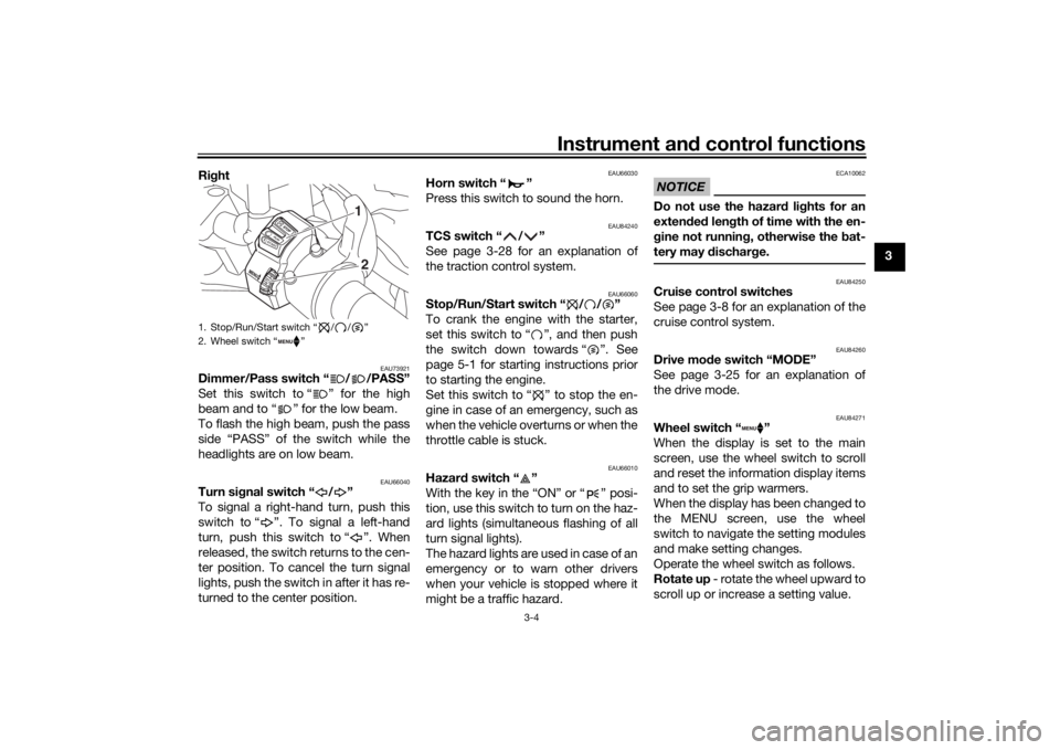
Stop/Run/Start switch “ / / ”
To crank the engine with the starter,
set this switch to “ ”, and then push
the switch down towards “ ”. See
page 5-1 for starting instructions prior
to starting the engine.
Set this switch to “ ” to stop the en-
gine in case of an emergency, such as
when the vehicle overturns or when the
throttle cable is stuck.
EAU66010
Hazar d switch “ ”
With the key in the “ON” or “ ” posi-
tion, use this switch to turn on the haz-
ard lights (simultaneous flashing of all
turn signal lights).
The hazard lights are used in case of an
emergency or to warn other drivers
when your vehicle is stopped where it
might be a traffic hazard.
NOTICE
ECA10062
Do not use the hazar d lig hts for an
exten ded len gth of time with the en-
g ine not runnin g, otherwise the bat-
tery may d ischarge.
EAU84250
Cruise control switches
See page 3-8 for an explanation of the
cruise control system.
EAU84260
Drive mo de switch “MODE”
See page 3-25 for an explanation of
the drive mode.
EAU84271
Wheel switch “ ”
When the display is set to the main
screen, use the wheel switch to scroll
and reset the information display items
and to set the grip warmers.
When the display has been changed to
the MENU screen, use the wheel
switch to navigate the setting modules
and make setting changes.
Operate the wheel switch as follows.
Rotate up - rotate the wheel upward to
scroll up or increase a setting value.
1. Stop/Run/Start switch “ / / ”
2. Wheel switch “ ”
1
2
UB1JE0E0.book Page 4 Tuesday, February 13, 2018 9:12 AM
Page 53 of 120

Instrument and control functions
3-38
3
EAU62550
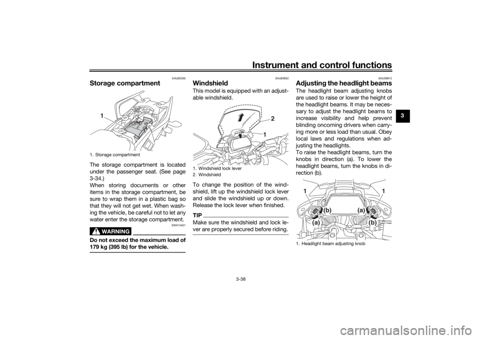
Stora ge compartmentThe storage compartment is located
under the passenger seat. (See page
3-34.)
When storing documents or other
items in the storage compartment, be
sure to wrap them in a plastic bag so
that they will not get wet. When wash-
ing the vehicle, be careful not to let any
water enter the storage compartment.
WARNING
EWA15401
Do not exceed the maximum loa d of
179 k g (395 l b) for the vehicle.
EAU83932
Win dshiel d This model is equipped with an adjust-
able windshield.
To change the position of the wind-
shield, lift up the windshield lock lever
and slide the windshield up or down.
Release the lock lever when finished.TIPMake sure the windshield and lock le-
ver are properly secured before riding.
EAU39612
A djustin g the hea dlig ht beamsThe headlight beam adjusting knobs
are used to raise or lower the height of
the headlight beams. It may be neces-
sary to adjust the headlight beams to
increase visibility and help prevent
blinding oncoming drivers when carry-
ing more or less load than usual. Obey
local laws and regulations when ad-
justing the headlights.
To raise the headlight beams, turn the
knobs in direction (a). To lower the
headlight beams, turn the knobs in di-
rection (b).
1. Storage compartment
1
1. Windshield lock lever
2. Windshield
1 2
1. Headlight beam adjusting knob
(a)
(b)
1
(b)
(a)
1
UB1JE0E0.book Page 38 Tuesday, February 13, 2018 9:12 AM
Page 101 of 120

Periodic maintenance an d a djustment
6-33
6
EAU77470
Hea dlig htsThis model is equipped with LED-type
headlights.
If a headlight does not come on, check
the fuses and then have a Yamaha
dealer check the vehicle.TIPWhen the headlights are set to low
beam, one headlight will come on.
When the headlights are set to high
beam or the passing switch is pushed,
both headlights should come on.NOTICE
ECA16581
Do not affix any type of tinte d film or
stickers to the head lig ht lens.
EAU54502
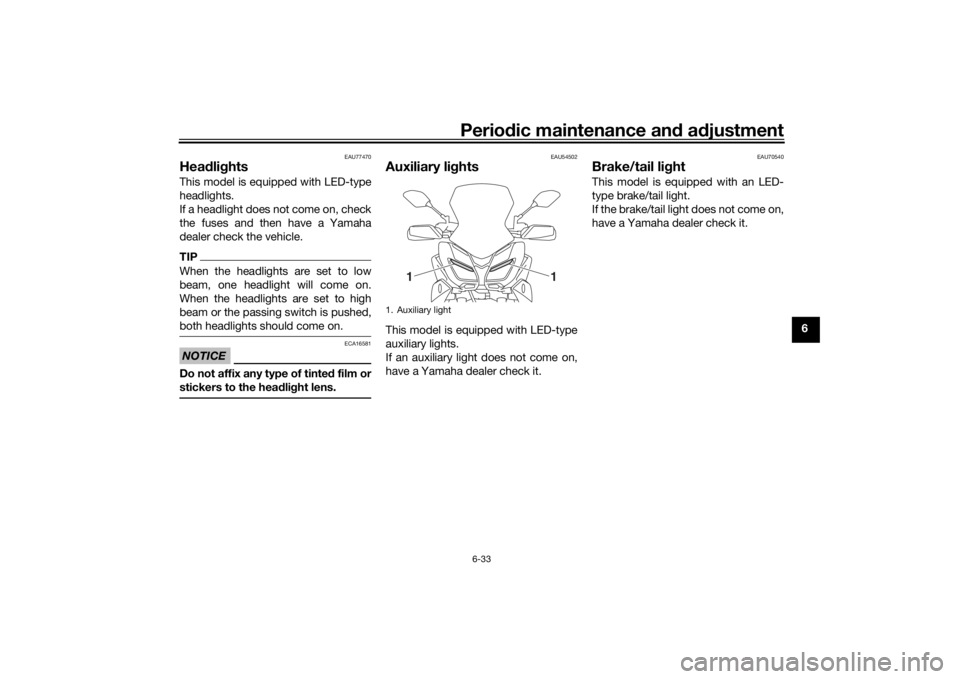
Auxiliary li ghtsThis model is equipped with LED-type
auxiliary lights.
If an auxiliary light does not come on,
have a Yamaha dealer check it.
EAU70540
Brake/tail li ghtThis model is equipped with an LED-
type brake/tail light.
If the brake/tail light does not come on,
have a Yamaha dealer check it.
1. Auxiliary light
1
1
UB1JE0E0.book Page 33 Tuesday, February 13, 2018 9:12 AM
Page 116 of 120

10-1
10
IndexAABS ....................................................... 3-27
ABS warning light ................................... 3-6
Air filter element .................................... 6-15
Auxiliary DC connector ......................... 3-44
Auxiliary DC jack ................................... 3-43
Auxiliary lights ....................................... 6-33BBattery .................................................. 6-29
Brake and clutch levers, checking and
lubricating ........................................... 6-26
Brake and shift pedals, checking and
lubricating ........................................... 6-26
Brake fluid, changing ............................ 6-22
Brake fluid level, checking .................... 6-21
Brake lever ............................................ 3-26
Brake lever free play, checking............. 6-19
Brake light switches.............................. 6-20
Brake pedal........................................... 3-27
Brake/tail light ....................................... 6-33CCables, checking and lubricating ......... 6-25
Canister................................................. 6-11
Care ........................................................ 7-1
Catalytic converter ................................ 3-33
Centerstand and sidestand, checking
and lubricating .................................... 6-27
Clutch lever ........................................... 3-25
Clutch lever free play, adjusting ........... 6-19
Coolant ................................................. 6-13
Cruise control indicator lights ................. 3-5
Cruise control switches .......................... 3-4
Cruise control system ............................. 3-8
DData recording, vehicle .......................... 9-2
Diagnostic connector ............................. 9-2
Dimmer/Pass switch .............................. 3-4
Display, main screen ............................ 3-11
Display, menu screen ........................... 3-15
D-mode (drive mode) ........................... 3-25
Drive chain, cleaning and lubricating ... 6-24
Drive chain slack .................................. 6-23
Drive mode switch.................................. 3-4EEngine break-in ...................................... 5-3
Engine idling speed, checking ............. 6-15
Engine oil .............................................. 6-11
Engine oil and Coolant warning light ...... 3-7
Engine serial number .............................. 9-1
Engine trouble warning light ................... 3-5FFront and rear brake pads, checking ... 6-20
Front fork, adjusting ............................. 3-39
Front fork, checking ............................. 6-28
Fuel ....................................................... 3-31
Fuel consumption, tips for reducing ...... 5-3
Fuel tank cap ........................................ 3-30
Fuel tank overflow hose ....................... 3-33
Fuses, replacing ................................... 6-31HHandlebar position, adjusting .............. 3-39
Handlebar switches ................................ 3-3
Hazard switch......................................... 3-4
Headlight beams, adjusting.................. 3-38
Headlights ............................................ 6-33
Helmet holder ....................................... 3-37
High beam indicator light ....................... 3-5 Horn switch .............................................3-4
IIdentification numbers ............................9-1
Ignition circuit cut-off system ...............3-45
Immobilizer system .................................3-1
Immobilizer system indi
cator light ..........3-7
Indicator lights and warning lights ..........3-5LLicense plate light bulb, replacing ........6-34MMain switch/steering lock .......................3-2
Maintenance and lubrication, periodic....6-5
Maintenance, emission control system ..................................................6-3
Matte color, caution ................................7-1
Model label .............................................9-1NNeutral indicator light ..............................3-5PPanel, removing and installing ................6-9
Parking ....................................................5-4
Part locations ..........................................2-1QQuick shift system ................................3-26RRider seat height, adjusting ..................3-35SSafety information ...................................1-1
Seats .....................................................3-34
Shift indicator light ..................................3-6
Shifting ....................................................5-2
Shift pedal .............................................3-26
Shock absorber assembly, adjusting ....3-41
Sidestand ..............................................3-44
UB1JE0E0.book Page 1 Tuesday, February 13, 2018 9:12 AM