wheel YAMAHA TTR110 2013 Owners Manual
[x] Cancel search | Manufacturer: YAMAHA, Model Year: 2013, Model line: TTR110, Model: YAMAHA TTR110 2013Pages: 88, PDF Size: 2.02 MB
Page 9 of 88

TABLE OF CONTENTS
LOCATION OF IMPORTANT
LABELS ............................................1-1
SAFETY INFORMATION .................. 2-1
DESCRIPTION .................................. 3-1
Left view .......................................... 3-1
Right view ........................................ 3-2
Controls and instruments ................3-3
INSTRUMENT AND CONTROL
FUNCTIONS ....................................... 4-1
Main switch ..................................... 4-1
Handlebar switches ........................ 4-1
Shift pedal ......................................4-2
Brake lever ..................................... 4-2
Brake pedal .................................... 4-3
Fuel tank cap .................................. 4-3
Fuel ................................................ 4-3
Fuel tank breather hose ................. 4-6
Fuel cock ........................................ 4-6
Starter (choke) lever ....................... 4-7
Kickstarter ......................................4-8
Seat ................................................ 4-8
Shock absorber assembly .............. 4-9
Sidestand ....................................... 4-9
Starting circuit cut-off system ......... 4-9 FOR YOUR SAFETY –
PRE-OPERATION CHECKS
............. 5-1
OPERATION AND IMPORTANT
RIDING POINTS ................................ 6-1
Starting and warming up a cold engine ......................................... 6-1
Starting a warm engine .................. 6-2
Shifting ........................................... 6-2
Engine break-in .............................. 6-3
Parking ........................................... 6-4
PERIODIC MAINTENANCE AND
ADJUSTMENT ................................... 7-1
Owner’s tool kit .............................. 7-2
Periodic maintenance chart for the emission control system ............. 7-3
General maintenance and lubrication chart .......................... 7-4
Removing and installing panels ..... 7-7
Checking the spark plug ................ 7-8
Engine oil ....................................... 7-9
Cleaning the air filter element ...... 7-11
Cleaning the spark arrester ......... 7-13
Adjusting the carburetor ............... 7-14
Adjusting the engine idling
speed ........................................ 7-14
Checking the throttle grip free play ........................................... 7-15
Valve clearance ........................... 7-15
Tires ............................................. 7-15 Spoke wheels ............................... 7-17
Adjusting the clutch free play ....... 7-17
Adjusting the brake lever free
play ........................................... 7-18
Adjusting the brake pedal free
play ........................................... 7-19
Checking the shift pedal ............... 7-20
Checking the front and rear brake shoes ........................................ 7-20
Drive chain slack .......................... 7-21
Cleaning and lubricating the drive chain ......................................... 7-22
Checking and lubricating the cables ....................................... 7-23
Checking and lubricating the throttle grip and cable ............... 7-23
Checking and lubricating the
brake lever ................................ 7-23
Checking and lubricating the brake pedal ............................... 7-24
Checking and lubricating the sidestand .................................. 7-24
Lubricating the swingarm pivots ... 7-24
Checking the front fork ................. 7-25
Checking the steering .................. 7-25
Checking the wheel bearings ....... 7-26
Battery .......................................... 7-26
Replacing the fuse ....................... 7-27
Supporting the motorcycle ........... 7-28
Front wheel .................................. 7-29
Rear wheel ................................... 7-30
U5B685E0.book Page 1 Tuesday, July 10, 2012 5:06 PM
Page 21 of 88

SAFETY INFORMATION
2-2
2
●
Many accidents involve inexperi-
enced operators. Make sure that you are qualified and that you only lend your mo-
torcycle to other qualified opera-
tors.
Know your skills and limits. Staying within your limits may
help you to avoid an accident.
We recommend that you prac- tice riding your motorcycle until
you have become thoroughly fa-
miliar with the motorcycle and all
of its controls.
●
Many accidents have been caused
by error of the motorcycle opera-
tor. A typical error made by the op-
erator is veering wide on a turn
due to excessive speed or under-
cornering (insufficient lean angle
for the speed). Never travel faster
than warranted by conditions.
●
Ride cautiously in unfamiliar ar-
eas. You may encounter hidden
obstacles that could cause an ac-
cident.
●
The posture of the operator is im-
portant for proper control. The op-
erator should keep both hands on the handlebar and both feet on the
operator footrests during operation
to maintain control of the motorcy-
cle.
●
Never ride under the influence of
alcohol or other drugs.
●
Be sure the transmission is in neu-
tral before starting the engine.
Protective Apparel
The majority of fatalities from motorcy-
cle accidents are the result of head in-
juries. The use of a safety helmet is the
single most critical factor in the preven-
tion or reduction of head injuries.
●
Always wear an approved helmet.
●
Wear a face shield or goggles.
Wind in your unprotected eyes
could contribute to an impairment
of vision that could delay seeing a
hazard.
●
The use of a jacket, heavy boots,
trousers, gloves, etc., is effective in
preventing or reducing abrasions
or lacerations.
●
Never wear loose-fitting clothes,
otherwise they could catch on the
control levers, footrests, or wheels
and cause injury or an accident.
●
Always wear protective clothing
that covers your legs, ankles, and
feet. The engine or exhaust sys-
tem become very hot during or af-
ter operation and can cause burns.
Avoid Carbon Monoxide Poisoning
All engine exhaust contains carbon
monoxide, a deadly gas. Breathing car-
bon monoxide can cause headaches,
dizziness, drowsiness, nausea, confu-
sion, and eventually death.
Carbon Monoxide is a colorless, odor-
less, tasteless gas which may be
present even if you do not see or smell
any engine exhaust. Deadly levels of
carbon monoxide can collect rapidly
and you can quickly be overcome and
unable to save yourself. Also, deadly
levels of carbon monoxide can linger
for hours or days in enclosed or poorly
ventilated areas. If you experience any
symptoms of carbon monoxide poison-
ing, leave the area immediately, get
fresh air, and SEEK MEDICAL TREAT-
MENT.
U5B685E0.book Page 2 Tuesday, July 10, 2012 5:06 PM
Page 23 of 88

SAFETY INFORMATION
2-4
2
ucts or having other modifications per-
formed to your vehicle that change any
of the vehicle’s design or operation
characteristics can put you and others
at greater risk of serious injury or death.
You are responsible for injuries related
to changes in the vehicle.
Keep the following guidelines in mind,
as well as those provided under “Load-
ing” when mounting accessories.
●
Never install accessories that
would impair the performance of
your motorcycle. Carefully inspect
the accessory before using it to
make sure that it does not in any
way reduce ground clearance or
cornering clearance, limit suspen-
sion travel, steering travel or con-
trol operation.
Accessories fitted to the handle- bar or the front fork area can
create instability due to improper
weight distribution. If accesso-
ries are added to the handlebar
or front fork area, they must be
as lightweight as possible and
should be kept to a minimum. Bulky or large accessories may
seriously affect the stability of
the motorcycle. Wind may at-
tempt to lift the motorcycle, or
the motorcycle may become un-
stable in cross winds.
Certain accessories can dis- place the operator from his or
her normal riding position. This
improper position limits the free-
dom of movement of the opera-
tor and may limit control ability,
therefore, such accessories are
not recommended.
●
Use caution when adding electri-
cal accessories. If electrical acces-
sories exceed the capacity of the
motorcycle’s electrical system, an
electric failure could result, which
could cause a dangerous loss of
lights or engine power.
Aftermarket Tires and Rims
The tires and rims that came with your
motorcycle were designed to match the
performance capabilities and to provide
the best combination of handling, brak-
ing, and comfort. Other tires, rims, siz-
es, and combinations may not be appropriate. Refer to page 7-15 for tire
specifications and more information on
replacing your tires.
Transporting the Motorcycle
Be sure to observe following instruc-
tions before transporting the motorcy-
cle in another vehicle.
●
Remove all loose items from the
motorcycle.
●
Check that the fuel cock (if
equipped) is in the “OFF” position
and that there are no fuel leaks.
●
Point the front wheel straight
ahead on the trailer or in the truck
bed, and choke it in a rail to pre-
vent movement.
●
Shift the transmission in gear (for
models with a manual transmis-
sion).
●
Secure the motorcycle with tie-
downs or suitable straps that are
attached to solid parts of the mo-
torcycle, such as the frame or up-
per front fork triple clamp (and not,
for example, to rubber-mounted
handlebars or turn signals, or parts
that could break). Choose the lo-
U5B685E0.book Page 4 Tuesday, July 10, 2012 5:06 PM
Page 39 of 88

FOR YOUR SAFETY – PRE-OPERATION CHECKS
5-2
5
Control cables Make sure that operation is smooth.
Lubricate if necessary. 7-23
Drive chain Check chain slack.
Adjust if necessary.
Check chain condition.
Lubricate if necessary.
7-21, 7-22
Wheels and tires Check for damage.
Check tire condition and tread depth.
Check air pressure.
Correct if necessary. 7-15, 7-17
Shift pedal Make sure that operation is smooth.
Correct if necessary. 7-20
Brake pedal Make sure that operation is smooth.
Lubricate pedal pivoting point if necessary.
7-24
Brake lever Make sure that operation is smooth.
Lubricate lever pivoting point if necessary. 7-23
Sidestand Make sure that operation is smooth.
Lubricate pivot if necessary. 7-24
Chassis fasteners Make sure that all nuts, bolts and screws are properly tightened.
Tighten if necessary.
—
Engine stop switch Check operation. 4-1
ITEM CHECKS PAGE
U5B685E0.book Page 2 Tuesday, July 10, 2012 5:06 PM
Page 47 of 88
PERIODIC MAINTENANCE AND ADJUSTMENT
7-4
7
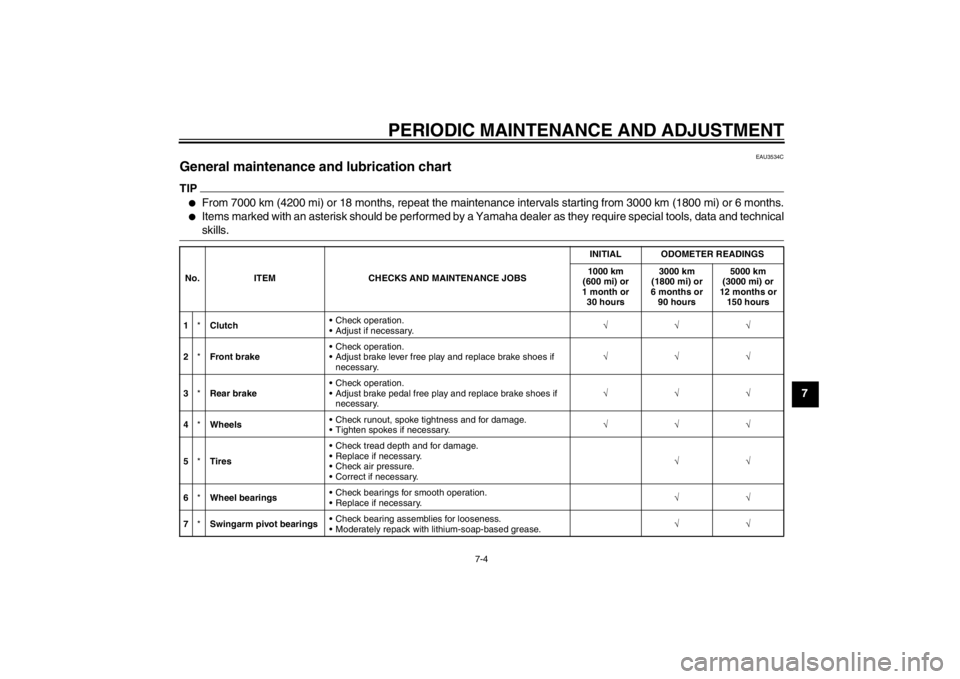
EAU3534C
General maintenance and lubrication chart TIP●
From 7000 km (4200 mi) or 18 months, repeat the maintenance intervals starting from 3000 km (1800 mi) or 6 months.
●
Items marked with an asterisk should be performed by a Yamaha dealer as they require special tools, data and technical
skills.
No. ITEM CHECKS AND MAINTENANCE JOBS INITIAL ODOMETER READINGS
1000 km
(600 mi) or
1 month or 30 hours 3000 km
(1800 mi) or
6 months or 90 hours 5000 km
(3000 mi) or
12 months or 150 hours
1 *Clutch Check operation.
Adjust if necessary. √√√
2 *Front brake Check operation.
Adjust brake lever free play and replace brake shoes if
necessary. √√√
3 *Rear brake Check operation.
Adjust brake pedal free play and replace brake shoes if
necessary. √√√
4 *Wheels Check runout, spoke tightness and for damage.
Tighten spokes if necessary. √√√
5 *Tires Check tread depth and for damage.
Replace if necessary.
Check air pressure.
Correct if necessary.
√√
6 *Wheel bearings Check bearings for smooth operation.
Replace if necessary.
√√
7 *Swingarm pivot bearings Check bearing assemblies for looseness.
Moderately repack with lithium-soap-based grease. √√
U5B685E0.book Page 4 Tuesday, July 10, 2012 5:06 PM
Page 59 of 88
PERIODIC MAINTENANCE AND ADJUSTMENT
7-16
7
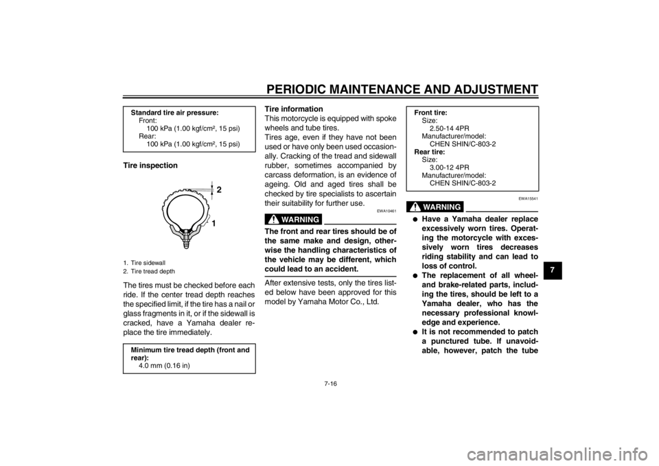
Tire inspection
The tires must be checked before each
ride. If the center tread depth reaches
the specified limit, if the tire has a nail or
glass fragments in it, or if the sidewall is
cracked, have a Yamaha dealer re-
place the tire immediately. Tire information
This motorcycle is equipped with spoke
wheels and tube tires.
Tires age, even if they have not been
used or have only been used occasion-
ally. Cracking of the tread and sidewall
rubber, sometimes accompanied by
carcass deformation, is an evidence of
ageing. Old and aged tires shall be
checked by tire specialists to ascertain
their suitability for further use.
WARNING
EWA10461
The front and rear tires should be of
the same make and design, other-
wise the handling characteristics of
the vehicle may be different, which
could lead to an accident.After extensive tests, only the tires list-
ed below have been approved for this
model by Yamaha Motor Co., Ltd.
WARNING
EWA15541
●
Have a Yamaha dealer replace
excessively worn tires. Operat-
ing the motorcycle with exces-
sively worn tires decreases
riding stability and can lead to
loss of control.
●
The replacement of all wheel-
and brake-related parts, includ-
ing the tires, should be left to a
Yamaha dealer, who has the necessary professional knowl-
edge and experience.
●
It is not recommended to patch
a punctured tube. If unavoid-
able, however, patch the tube
Standard tire air pressure: Front:
100 kPa (1.00 kgf/cm², 15 psi)
Rear:
100 kPa (1.00 kgf/cm², 15 psi)1. Tire sidewall
2. Tire tread depthMinimum tire tread depth (front and
rear): 4.0 mm (0.16 in)
12
Front tire:Size:
2.50-14 4PR
Manufacturer/model:
CHEN SHIN/C-803-2
Rear tire: Size:
3.00-12 4PR
Manufacturer/model: CHEN SHIN/C-803-2
U5B685E0.book Page 16 Tuesday, July 10, 2012 5:06 PM
Page 60 of 88
PERIODIC MAINTENANCE AND ADJUSTMENT
7-17
7very carefully and replace it as
soon as possible with a high-
quality product.
●
Ride conservatively after
changing a tire since the tire
must seat itself on the rim prop-
erly. Failure to allow proper
seating may cause tire failure,
which may result in damage to
the motorcycle and injury to the
rider.
EAU21943
Spoke wheels
WARNING
EWA10610
The wheels on this model are not de-
signed for use with tubeless tires.
Do not attempt to use tubeless tires
on this model.To maximize the performance, durabil-
ity, and safe operation of your motorcy-
cle, note the following points regarding
the specified wheels.●
The wheel rims should be checked
for cracks, bends, warpage or oth-
er damage, and the spokes for
looseness or damage before each
ride. If any damage is found, have
a Yamaha dealer replace the
wheel. Do not attempt even the
smallest repair to the wheel. A de-
formed or cracked wheel must be
replaced.
●
The wheel should be balanced
whenever either the tire or wheel
has been changed or replaced. An
unbalanced wheel can result in
poor performance, adverse han-
dling characteristics, and a short-
ened tire life.
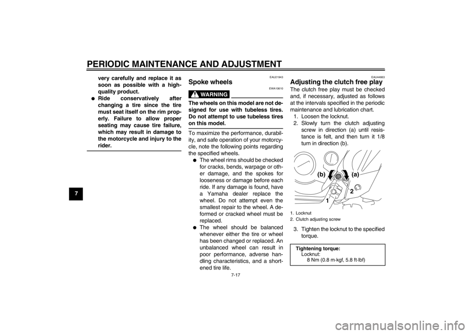
EAU44663
Adjusting the clutch free play The clutch free play must be checked
and, if necessary, adjusted as follows
at the intervals specified in the periodic
maintenance and lubrication chart.
1. Loosen the locknut.
2. Slowly turn the clutch adjusting screw in direction (a) until resis-
tance is felt, and then turn it 1/8
turn in direction (b).
3. Tighten the locknut to the specified torque.1. Locknut
2. Clutch adjusting screwTightening torque:Locknut:
8 Nm (0.8 m·kgf, 5.8 ft·lbf)
1 2
(a)
(b)
U5B685E0.book Page 17 Tuesday, July 10, 2012 5:06 PM
Page 62 of 88
PERIODIC MAINTENANCE AND ADJUSTMENT
7-19
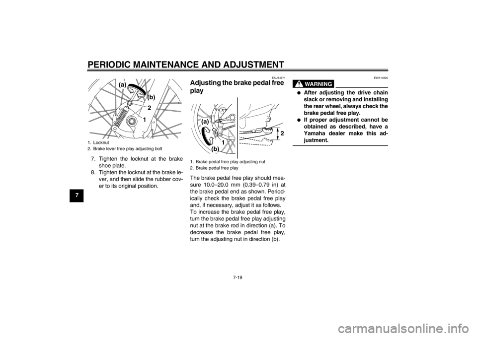
77. Tighten the locknut at the brake
shoe plate.
8. Tighten the locknut at the brake le- ver, and then slide the rubber cov-
er to its original position.
EAU44671
Adjusting the brake pedal free
play The brake pedal free play should mea-
sure 10.0–20.0 mm (0.39–0.79 in) at
the brake pedal end as shown. Period-
ically check the brake pedal free play
and, if necessary, adjust it as follows.
To increase the brake pedal free play,
turn the brake pedal free play adjusting
nut at the brake rod in direction (a). To
decrease the brake pedal free play,
turn the adjusting nut in direction (b).
WARNING
EWA14820
●
After adjusting the drive chain
slack or removing and installing
the rear wheel, always check the
brake pedal free play.
●
If proper adjustment cannot be
obtained as described, have a
Yamaha dealer make this ad-
justment.
1. Locknut
2. Brake lever free play adjusting bolt
21(b)
(a)
1. Brake pedal free play adjusting nut
2. Brake pedal free play
U5B685E0.book Page 19 Tuesday, July 10, 2012 5:06 PM
Page 65 of 88
PERIODIC MAINTENANCE AND ADJUSTMENT
7-22
7
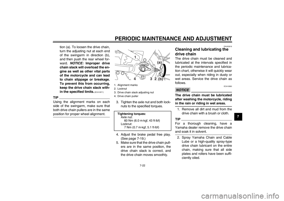
tion (a). To loosen the drive chain,
turn the adjusting nut at each end
of the swingarm in direction (b),
and then push the rear wheel for-
ward.
NOTICE: Improper drive
chain slack will overload the en-
gine as well as other vital parts
of the motorcycle and can lead
to chain slippage or breakage.
To prevent this from occurring,
keep the drive chain slack with-
in the specified limits.
[ECA10571]
TIPUsing the alignment marks on each
side of the swingarm, make sure that
both drive chain pullers are in the same
position for proper wheel alignment.
3. Tighten the axle nut and both lock- nuts to the specified torques.
4. Adjust the brake pedal free play. (See page 7-19.)
5. Make sure that the drive chain pull- ers are in the same position, the
drive chain slack is correct, and
the drive chain moves smoothly.
EAU23016
Cleaning and l ubricating the
drive chain The drive chain must be cleaned and
lubricated at the intervals specified in
the periodic maintenance and lubrica-
tion chart, otherwise it will quickly wear
out, especially when riding in dusty or
wet areas. Service the drive chain as
follows.NOTICE
ECA10583
The drive chain must be lubricated
after washing the motorcycle, riding
in the rain or riding in wet areas.1. Remove all dirt and mud from the
drive chain with a brush or cloth.TIPFor a thorough cleaning, have a
Yamaha dealer remove the drive chain
and soak it in solvent.2. Spray Yamaha Chain and CableLube or a high-quality spray-type
drive chain lubricant on the entire
chain, making sure that all side
plates and rollers have been suffi-
ciently oiled.
1. Alignment marks
2. Locknut
3. Drive chain slack adjusting nut
4. Drive chain puller
Tightening torques:Axle nut:60 Nm (6.0 m·kgf, 43 ft·lbf)
Locknut: 7 Nm (0.7 m·kgf, 5.1 ft·lbf)
(a)
(b)
432 1
U5B685E0.book Page 22 Tuesday, July 10, 2012 5:06 PM
Page 68 of 88
PERIODIC MAINTENANCE AND ADJUSTMENT
7-25
7
EAU23272
Checking the front fork The condition and operation of the front
fork must be checked as follows at the
intervals specified in the periodic main-
tenance and lubrication chart.
To check the condition
Check the inner tubes for scratches,
damage and excessive oil leakage.
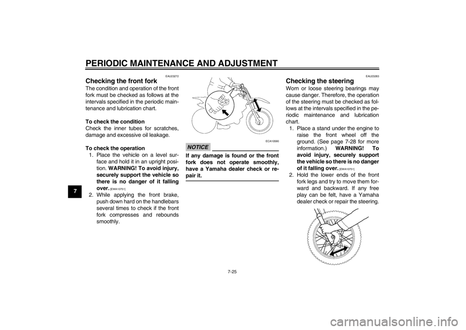
To check the operation1. Place the vehicle on a level sur- face and hold it in an upright posi-
tion. WARNING! To avoid injury,
securely support the vehicle so
there is no danger of it falling
over.
[EWA10751]
2. While applying the front brake, push down hard on the handlebars
several times to check if the front
fork compresses and rebounds
smoothly.
NOTICE
ECA10590
If any damage is found or the front
fork does not operate smoothly,
have a Yamaha dealer check or re-
pair it.
EAU23283
Checking the steering Worn or loose steering bearings may
cause danger. Therefore, the operation
of the steering must be checked as fol-
lows at the intervals specified in the pe-
riodic maintenance and lubrication
chart.1. Place a stand under the engine to raise the front wheel off the
ground. (See page 7-28 for more
information.) WARNING! To
avoid injury, securely support
the vehicle so there is no danger
of it falling over.
[EWA10751]
2. Hold the lower ends of the front fork legs and try to move them for-
ward and backward. If any free
play can be felt, have a Yamaha
dealer check or repair the steering.
U5B685E0.book Page 25 Tuesday, July 10, 2012 5:06 PM