lock YAMAHA TTR125 2001 Notices Demploi (in French)
[x] Cancel search | Manufacturer: YAMAHA, Model Year: 2001, Model line: TTR125, Model: YAMAHA TTR125 2001Pages: 508, PDF Size: 16.81 MB
Page 300 of 508
4 - 46
ENGCLUTCH AND PRIMARY DRIVEN GEAR
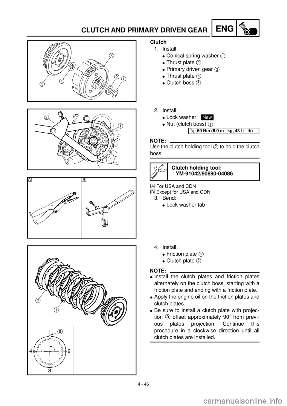
Clutch
1. Install:
lConical spring washer 1
lThrust plate 2
lPrimary driven gear 3
lThrust plate 4
lClutch boss 5
2. Install:
lLock washer
lNut (clutch boss) 1
NOTE:
Use the clutch holding tool 2 to hold the clutch
boss.
For USA and CDN
õExcept for USA and CDN
3. Bend:
lLock washer tab
Clutch holding tool:
YM-91042/90890-04086
New
T R..60 Nm (6.0 m · kg, 43 ft · lb)
õ
4. Install:
lFriction plate 1
lClutch plate 2
NOTE:
lInstall the clutch plates and friction plates
alternately on the clutch boss, starting with a
friction plate and ending with a friction plate.
lApply the engine oil on the friction plates and
clutch plates.
lBe sure to install a clutch plate with projec-
tion a offset approximately 90˚ from previ-
ous plates projection. Continue this
procedure in a clockwise direction until all
clutch plates are installed.
Page 304 of 508
4 - 48
ENGCLUTCH AND PRIMARY DRIVEN GEAR
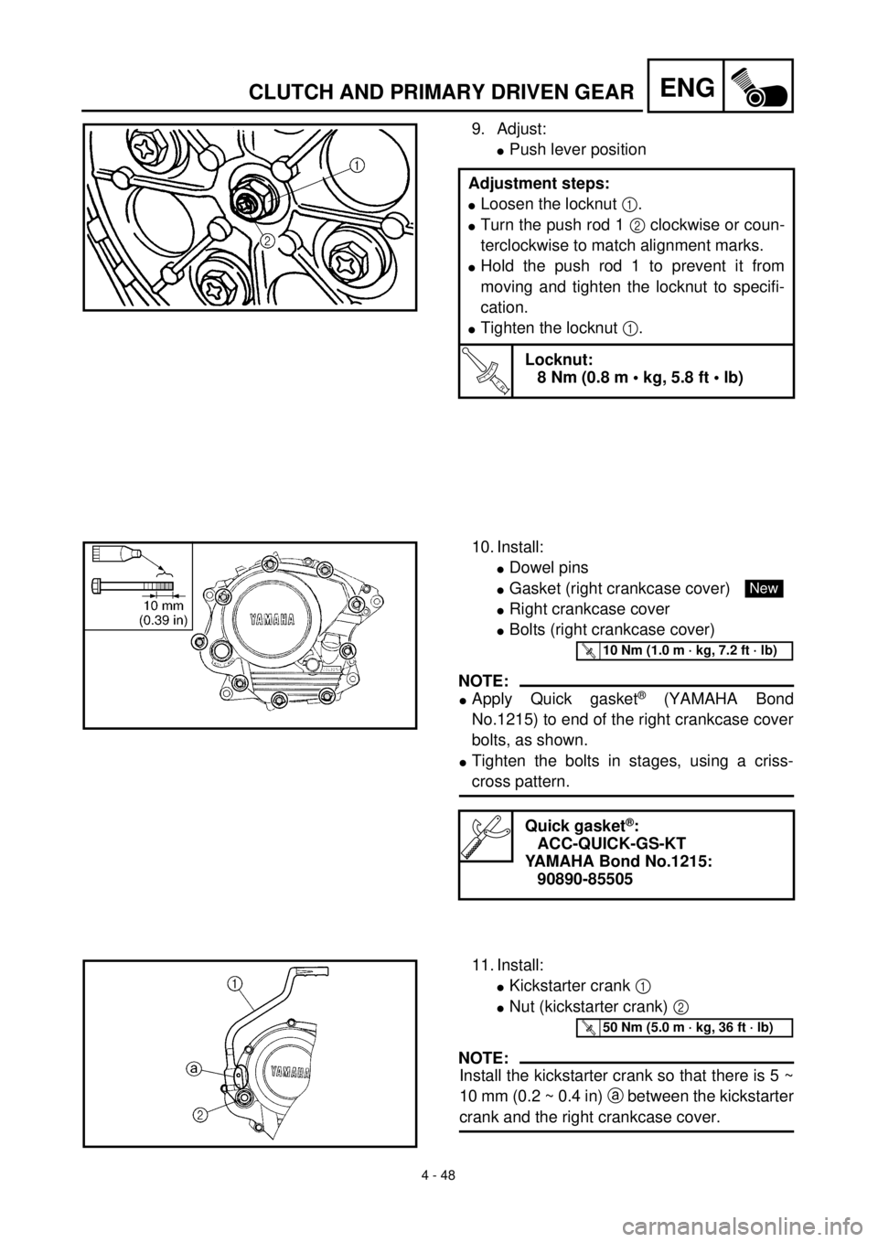
9. Adjust:
lPush lever position
Adjustment steps:
lLoosen the locknut 1.
lTurn the push rod 1 2 clockwise or coun-
terclockwise to match alignment marks.
lHold the push rod 1 to prevent it from
moving and tighten the locknut to specifi-
cation.
lTighten the locknut 1.
T R..
Locknut:
8 Nm (0.8 m • kg, 5.8 ft • lb)
10. Install:
lDowel pins
lGasket (right crankcase cover)
lRight crankcase cover
lBolts (right crankcase cover)
NOTE:
lApply Quick gasket® (YAMAHA Bond
No.1215) to end of the right crankcase cover
bolts, as shown.
lTighten the bolts in stages, using a criss-
cross pattern.
Quick gasket®:
ACC-QUICK-GS-KT
YAMAHA Bond No.1215:
90890-85505
New
T R..10 Nm (1.0 m · kg, 7.2 ft · lb)
11. Install:
lKickstarter crank 1
lNut (kickstarter crank) 2
NOTE:
Install the kickstarter crank so that there is 5 ~
10 mm (0.2 ~ 0.4 in) a between the kickstarter
crank and the right crankcase cover.
T R..50 Nm (5.0 m · kg, 36 ft · lb)
Page 320 of 508
4 - 56
ENGKICK AXLE AND SHIFT SHAFT
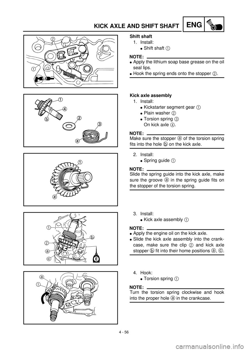
Shift shaft
1. Install:
lShift shaft 1
NOTE:
lApply the lithium soap base grease on the oil
seal lips.
lHook the spring ends onto the stopper 2.
Kick axle assembly
1. Install:
lKickstarter segment gear 1
lPlain washer 2
lTorsion spring 3
On kick axle 4.
NOTE:
Make sure the stopper a of the torsion spring
fits into the hole b on the kick axle.
2. Install:
lSpring guide 1
NOTE:
Slide the spring guide into the kick axle, make
sure the groove a in the spring guide fits on
the stopper of the torsion spring.
3. Install:
lKick axle assembly 1
NOTE:
lApply the engine oil on the kick axle.
lSlide the kick axle assembly into the crank-
case, make sure the clip 2 and kick axle
stopper b fit into their home positions a, c.
4. Hook:
lTorsion spring 1
NOTE:
Turn the torsion spring clockwise and hook
into the proper hole a in the crankcase.
Page 392 of 508
5 - 14
CHASFRONT BRAKE (TT-R125LW)
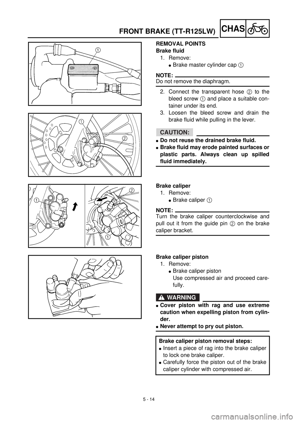
REMOVAL POINTS
Brake fluid
1. Remove:
lBrake master cylinder cap 1
NOTE:
Do not remove the diaphragm.
2. Connect the transparent hose 2 to the
bleed screw 1 and place a suitable con-
tainer under its end.
3. Loosen the bleed screw and drain the
brake fluid while pulling in the lever.
CAUTION:
lDo not reuse the drained brake fluid.
lBrake fluid may erode painted surfaces or
plastic parts. Always clean up spilled
fluid immediately.
Brake caliper
1. Remove:
lBrake caliper 1
NOTE:
Turn the brake caliper counterclockwise and
pull out it from the guide pin 2 on the brake
caliper bracket.
Brake caliper piston
1. Remove:
lBrake caliper piston
Use compressed air and proceed care-
fully.
WARNING
lCover piston with rag and use extreme
caution when expelling piston from cylin-
der.
lNever attempt to pry out piston.
Brake caliper piston removal steps:
lInsert a piece of rag into the brake caliper
to lock one brake caliper.
lCarefully force the piston out of the brake
caliper cylinder with compressed air.
Page 393 of 508
5 - 14
CHAS
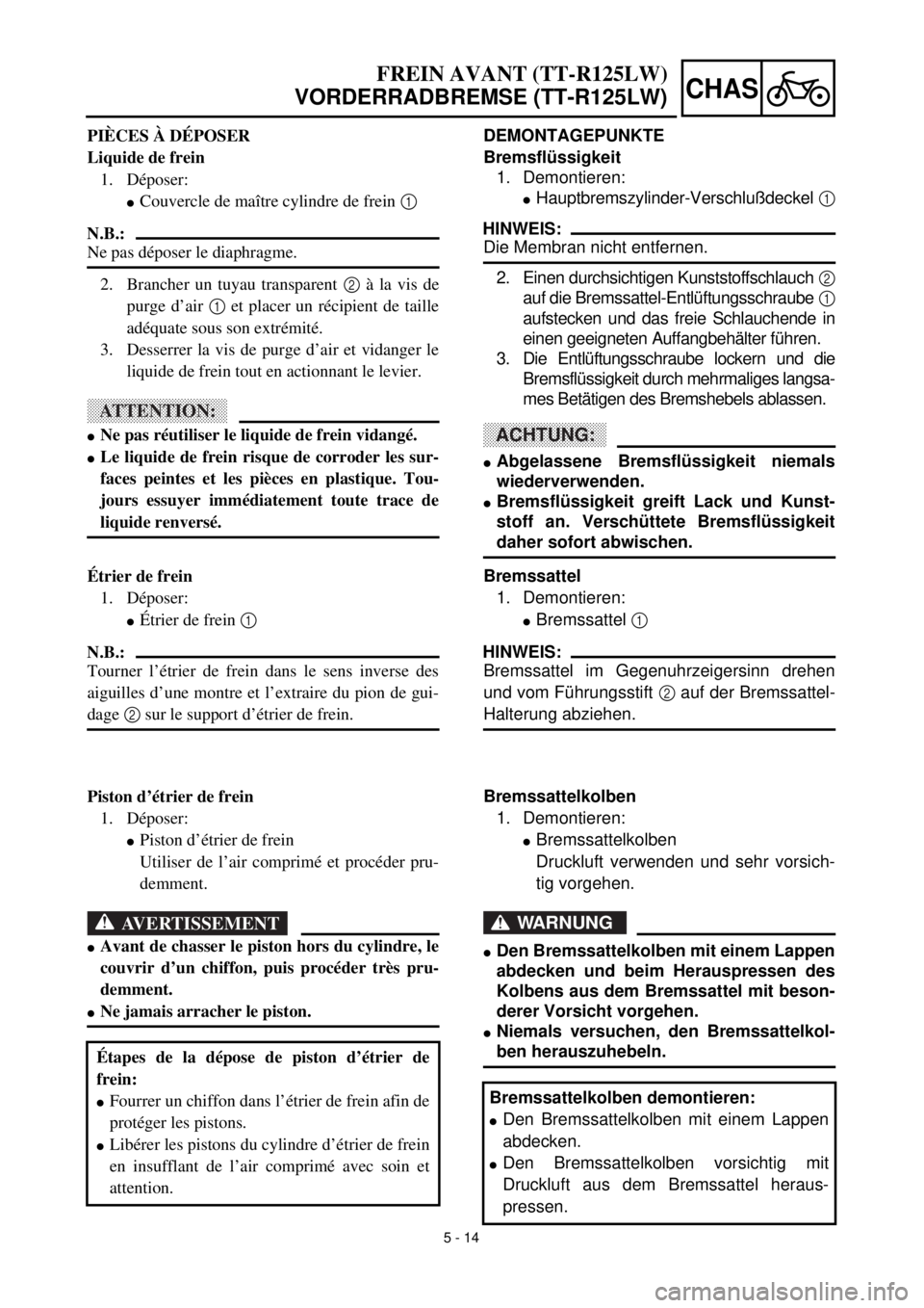
DEMONTAGEPUNKTE
Bremsflüssigkeit
1. Demontieren:
lHauptbremszylinder-Verschlußdeckel 1
HINWEIS:
Die Membran nicht entfernen.
2. Einen durchsichtigen Kunststoffschlauch 2
auf die Bremssattel-Entlüftungsschraube 1
aufstecken und das freie Schlauchende in
einen geeigneten Auffangbehälter führen.
3. Die Entlüftungsschraube lockern und die
Bremsflüssigkeit durch mehrmaliges langsa-
mes Betätigen des Bremshebels ablassen.
ACHTUNG:
lAbgelassene Bremsflüssigkeit niemals
wiederverwenden.
lBremsflüssigkeit greift Lack und Kunst-
stoff an. Verschüttete Bremsflüssigkeit
daher sofort abwischen.
Bremssattel
1. Demontieren:
lBremssattel 1
HINWEIS:
Bremssattel im Gegenuhrzeigersinn drehen
und vom Führungsstift 2 auf der Bremssattel-
Halterung abziehen.
Bremssattelkolben
1. Demontieren:
lBremssattelkolben
Druckluft verwenden und sehr vorsich-
tig vorgehen.
WARNUNG
lDen Bremssattelkolben mit einem Lappen
abdecken und beim Herauspressen des
Kolbens aus dem Bremssattel mit beson-
derer Vorsicht vorgehen.
lNiemals versuchen, den Bremssattelkol-
ben herauszuhebeln.
Bremssattelkolben demontieren:
lDen Bremssattelkolben mit einem Lappen
abdecken.
lDen Bremssattelkolben vorsichtig mit
Druckluft aus dem Bremssattel heraus-
pressen.
FREIN AVANT (TT-R125LW)
VORDERRADBREMSE (TT-R125LW)
PIÈCES À DÉPOSER
Liquide de frein
1. Déposer:
lCouvercle de maître cylindre de frein 1
N.B.:
Ne pas déposer le diaphragme.
2. Brancher un tuyau transparent 2 à la vis de
purge d’air 1 et placer un récipient de taille
adéquate sous son extrémité.
3. Desserrer la vis de purge d’air et vidanger le
liquide de frein tout en actionnant le levier.
ATTENTION:
lNe pas réutiliser le liquide de frein vidangé.
lLe liquide de frein risque de corroder les sur-
faces peintes et les pièces en plastique. Tou-
jours essuyer immédiatement toute trace de
liquide renversé.
Étrier de frein
1. Déposer:
lÉtrier de frein 1
N.B.:
Tourner l’étrier de frein dans le sens inverse des
aiguilles d’une montre et l’extraire du pion de gui-
dage 2 sur le support d’étrier de frein.
Piston d’étrier de frein
1. Déposer:
lPiston d’étrier de frein
Utiliser de l’air comprimé et procéder pru-
demment.
AVERTISSEMENT
lAvant de chasser le piston hors du cylindre, le
couvrir d’un chiffon, puis procéder très pru-
demment.
lNe jamais arracher le piston.
Étapes de la dépose de piston d’étrier de
frein:
lFourrer un chiffon dans l’étrier de frein afin de
protéger les pistons.
lLibérer les pistons du cylindre d’étrier de frein
en insufflant de l’air comprimé avec soin et
attention.
Page 400 of 508
5 - 18
CHASFRONT BRAKE (TT-R125LW)
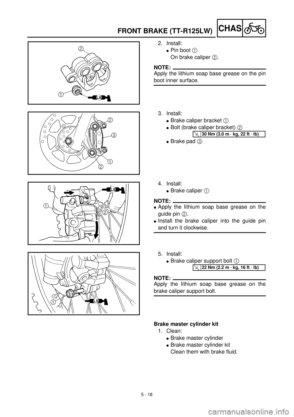
2. Install:
lPin boot 1
On brake caliper 2.
NOTE:
Apply the lithium soap base grease on the pin
boot inner surface.
3. Install:
lBrake caliper bracket 1
lBolt (brake caliper bracket) 2
lBrake pad 3
T R..30 Nm (3.0 m · kg, 22 ft · lb)
4. Install:
lBrake caliper 1
NOTE:
lApply the lithium soap base grease on the
guide pin 2.
lInstall the brake caliper into the guide pin
and turn it clockwise.
5. Install:
lBrake caliper support bolt 1
NOTE:
Apply the lithium soap base grease on the
brake caliper support bolt.
T R..22 Nm (2.2 m · kg, 16 ft · lb)
Brake master cylinder kit
1. Clean:
lBrake master cylinder
lBrake master cylinder kit
Clean them with brake fluid.
Page 408 of 508
5 - 22
CHAS
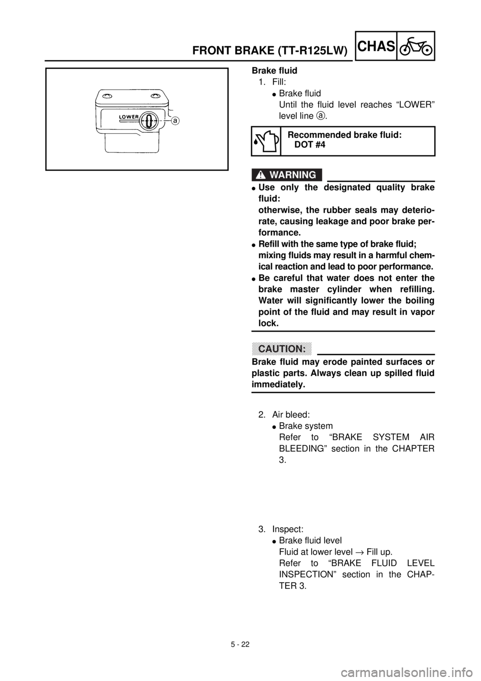
Brake fluid
1. Fill:
l
Brake fluid
Until the fluid level reaches “LOWER”
level line
a
.
WARNING
l
Use only the designated quality brake
fluid:
otherwise, the rubber seals may deterio-
rate, causing leakage and poor brake per-
formance.
l
Refill with the same type of brake fluid;
mixing fluids may result in a harmful chem-
ical reaction and lead to poor performance.
l
Be careful that water does not enter the
brake master cylinder when refilling.
Water will significantly lower the boiling
point of the fluid and may result in vapor
lock.
CAUTION:
Brake fluid may erode painted surfaces or
plastic parts. Always clean up spilled fluid
immediately.
Recommended brake fluid:
DOT #4
2. Air bleed:
l
Brake system
Refer to “BRAKE SYSTEM AIR
BLEEDING” section in the CHAPTER
3.
3. Inspect:
l
Brake fluid level
Fluid at lower level
®
Fill up.
Refer to “BRAKE FLUID LEVEL
INSPECTION” section in the CHAP-
TER 3.
FRONT BRAKE (TT-R125LW)
Page 409 of 508
5 - 22
CHAS
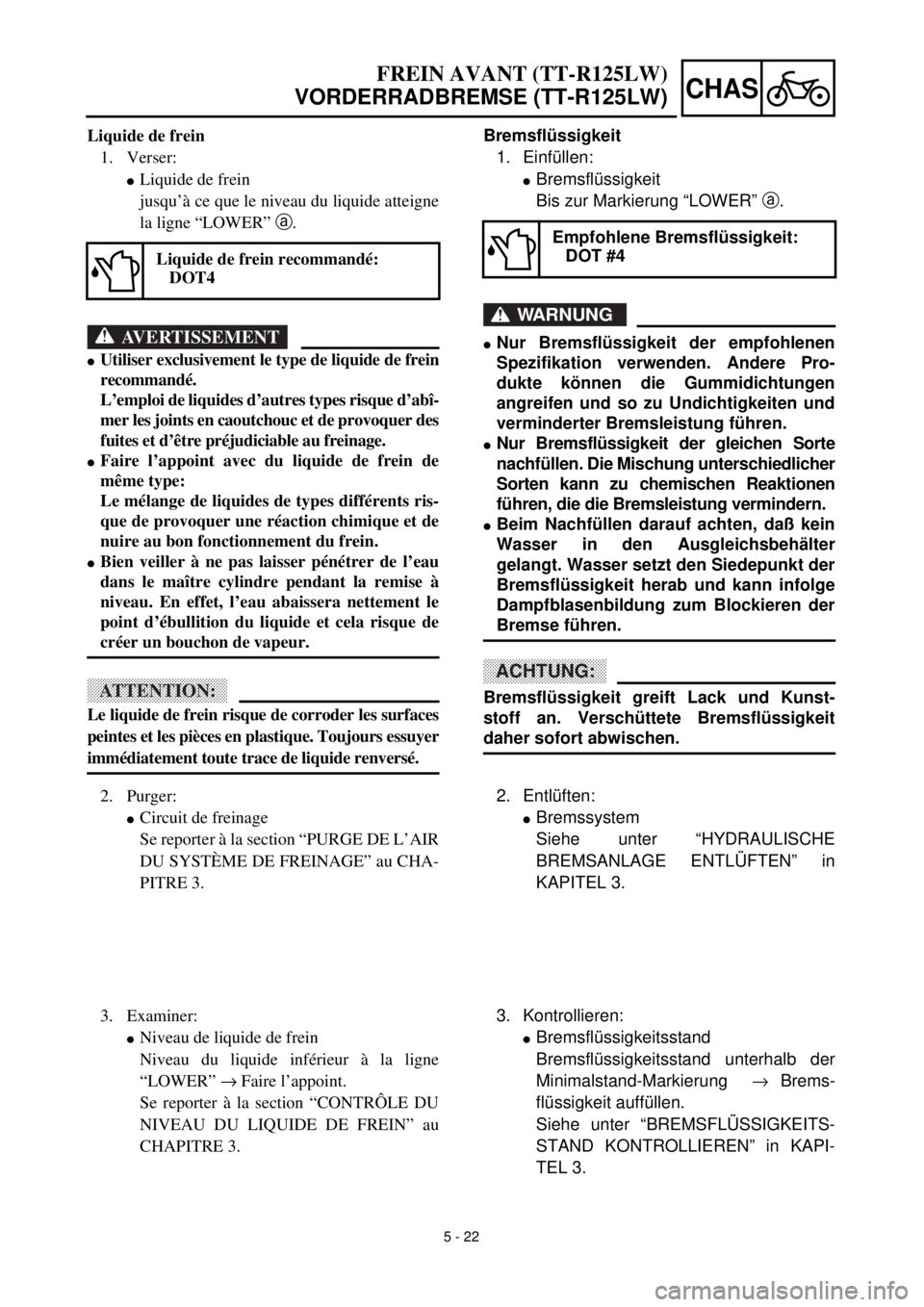
Bremsflüssigkeit
1. Einfüllen:
l
Bremsflüssigkeit
Bis zur Markierung “LOWER”
a
.
WARNUNG
l
Nur Bremsflüssigkeit der empfohlenen
Spezifikation verwenden. Andere Pro-
dukte können die Gummidichtungen
angreifen und so zu Undichtigkeiten und
verminderter Bremsleistung führen.
l
Nur Bremsflüssigkeit der gleichen Sorte
nachfüllen. Die Mischung unterschiedlicher
Sorten kann zu chemischen Reaktionen
führen, die die Bremsleistung vermindern.
l
Beim Nachfüllen darauf achten, daß kein
Wasser in den Ausgleichsbehälter
gelangt. Wasser setzt den Siedepunkt der
Bremsflüssigkeit herab und kann infolge
Dampfblasenbildung zum Blockieren der
Bremse führen.
ACHTUNG:
Bremsflüssigkeit greift Lack und Kunst-
stoff an. Verschüttete Bremsflüssigkeit
daher sofort abwischen.
Empfohlene Bremsflüssigkeit:
DOT #4
2. Entlüften:
l
Bremssystem
Siehe unter “HYDRAULISCHE
BREMSANLAGE ENTLÜFTEN” in
KAPITEL 3.
3. Kontrollieren:
l
Bremsflüssigkeitsstand
Bremsflüssigkeitsstand unterhalb der
Minimalstand-Markierung
®
Brems-
flüssigkeit auffüllen.
Siehe unter “BREMSFLÜSSIGKEITS-
STAND KONTROLLIEREN” in KAPI-
TEL 3.
FREIN AVANT (TT-R125LW)
VORDERRADBREMSE (TT-R125LW)
Liquide de frein
1. Verser:
l
Liquide de frein
jusqu’à ce que le niveau du liquide atteigne
la ligne “LOWER”
a
.
AVERTISSEMENT
l
Utiliser exclusivement le type de liquide de frein
recommandé.
L’emploi de liquides d’autres types risque d’abî-
mer les joints en caoutchouc et de provoquer des
fuites et d’être préjudiciable au freinage.
l
Faire l’appoint avec du liquide de frein de
même type:
Le mélange de liquides de types différents ris-
que de provoquer une réaction chimique et de
nuire au bon fonctionnement du frein.
l
Bien veiller à ne pas laisser pénétrer de l’eau
dans le maître cylindre pendant la remise à
niveau. En effet, l’eau abaissera nettement le
point d’ébullition du liquide et cela risque de
créer un bouchon de vapeur.
ATTENTION:
Le liquide de frein risque de corroder les surfaces
peintes et les pièces en plastique. Toujours essuyer
immédiatement toute trace de liquide renversé.
Liquide de frein recommandé:
DOT4
2. Purger:
l
Circuit de freinage
Se reporter à la section “PURGE DE L’AIR
DU SYSTÈME DE FREINAGE” au CHA-
PITRE 3.
3. Examiner:
l
Niveau de liquide de frein
Niveau du liquide inférieur à la ligne
“LOWER”
®
Faire l’appoint.
Se reporter à la section “CONTRÔLE DU
NIVEAU DU LIQUIDE DE FREIN” au
CHAPITRE 3.
Page 414 of 508
5 - 25
CHAS
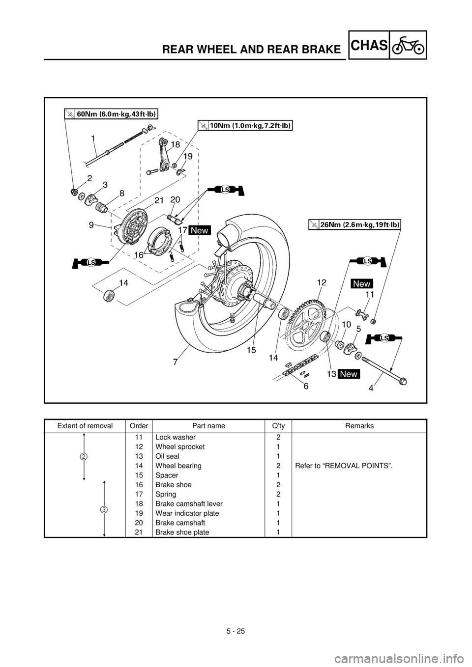
Extent of removal Order Part name Q’ty Remarks
11 Lock washer 2
12 Wheel sprocket 1
13 Oil seal 1
14 Wheel bearing 2 Refer to “REMOVAL POINTS”.
15 Spacer 1
16 Brake shoe 2
17 Spring 2
18 Brake camshaft lever 1
19 Wear indicator plate 1
20 Brake camshaft 1
21 Brake shoe plate 1
3
2
REAR WHEEL AND REAR BRAKE
Page 424 of 508
5 - 30
CHASREAR WHEEL AND REAR BRAKE
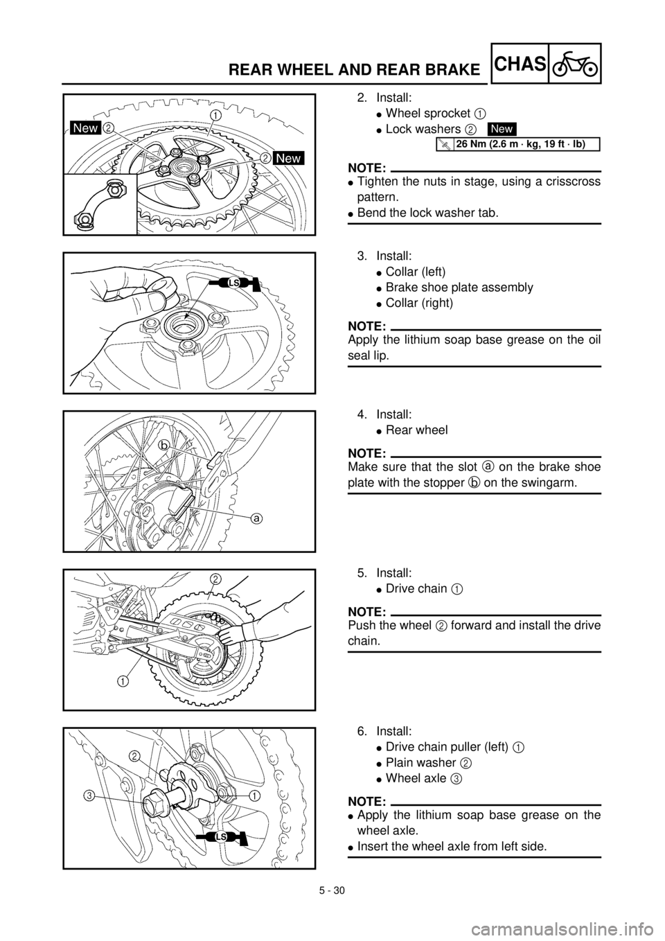
2. Install:
lWheel sprocket 1
lLock washers 2
NOTE:
lTighten the nuts in stage, using a crisscross
pattern.
lBend the lock washer tab.
New
T R..26 Nm (2.6 m · kg, 19 ft · lb)
3. Install:
lCollar (left)
lBrake shoe plate assembly
lCollar (right)
NOTE:
Apply the lithium soap base grease on the oil
seal lip.
4. Install:
lRear wheel
NOTE:
Make sure that the slot a on the brake shoe
plate with the stopper b on the swingarm.
5. Install:
lDrive chain 1
NOTE:
Push the wheel 2 forward and install the drive
chain.
6. Install:
lDrive chain puller (left) 1
lPlain washer 2
lWheel axle 3
NOTE:
lApply the lithium soap base grease on the
wheel axle.
lInsert the wheel axle from left side.