relay YAMAHA TTR125 2002 Notices Demploi (in French)
[x] Cancel search | Manufacturer: YAMAHA, Model Year: 2002, Model line: TTR125, Model: YAMAHA TTR125 2002Pages: 509, PDF Size: 16.83 MB
Page 86 of 509

SPEC
2 - 17
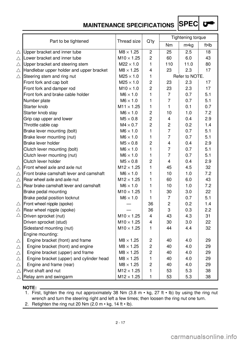
MAINTENANCE SPECIFICATIONS
NOTE:
1. First, tighten the ring nut approximately 38 Nm (3.8 m • kg, 27 ft • lb) by using the ring nut
wrench and turn the steering right and left a few times; then loosen the ring nut one turn.
2. Retighten the ring nut 20 Nm (2.0 m • kg, 14 ft • lb).Part to be tightened Thread size Q’tyTightening torque
Nm m•kg ft•lb
Upper bracket and inner tube M8 ´ 1.25 2 25 2.5 18
Lower bracket and inner tube M10 ´ 1.25 2 60 6.0 43
Upper bracket and steering stem M22 ´ 1.0 1 110 11.0 80
Handlebar upper holder and upper bracket M8 ´ 1.25 4 23 2.3 17
Steering stem and ring nut M25 ´ 1.0 1 Refer to NOTE.
Front fork and cap bolt M25 ´ 1.0 2 23 2.3 17
Front fork and damper rod M10 ´ 1.0 2 23 2.3 17
Front fork and brake cable holder M6 ´ 1.0 1 7 0.7 5.1
Number plate M6 ´ 1.0 1 7 0.7 5.1
Starter knob M11 ´ 1.25 1 1 0.1 0.7
Starter knob stay M6 ´ 1.0 2 10 1.0 7.2
Grip cap upper and lower M5 ´ 0.8 2 4 0.4 2.9
Throttle cable cap M4 ´ 0.7 2 2 0.2 1.4
Brake lever mounting (bolt) M6 ´ 1.0 1 7 0.7 5.1
Brake lever mounting (nut) M6 ´ 1.0 1 7 0.7 5.1
Brake lever holder M5 ´ 0.8 2 4 0.4 2.9
Clutch lever mounting (bolt) M6 ´ 1.0 1 7 0.7 5.1
Clutch lever mounting (nut) M6 ´ 1.0 1 7 0.7 5.1
Clutch lever holder M5 ´ 0.8 2 4 0.4 2.9
Front wheel axle and axle nut M12 ´ 1.25 1 45 4.5 32
Front brake camshaft lever and camshaft M6 ´ 1.0 1 10 1.0 7.2
Rear wheel axle and axle nut M12 ´ 1.25 1 60 6.0 43
Rear brake camshaft lever and camshaft M6 ´ 1.0 1 10 1.0 7.2
Brake pedal mounting M10 ´ 1.25 1 30 3.0 22
Brake pedal position locknut M6 ´ 1.0 1 7 0.7 5.1
Front wheel nipple (spoke) — 36 2 0.2 1.4
Rear wheel nipple (spoke) — 36 3 0.3 2.2
Driven sprocket (nut) M10 ´ 1.25 4 43 4.3 31
Driven sprocket (stud) M10 ´ 1.25 4 30 3.0 22
Sidestand mounting (nut) M10 ´ 1.25 1 44 4.4 32
Engine mounting:
Engine bracket (front) and frame M8 ´ 1.25 2 40 4.0 29
Engine bracket (front) and engine M8 ´ 1.25 2 40 4.0 29
Engine bracket (upper) and frame M8 ´ 1.25 2 40 4.0 29
Engine bracket (upper) and cylinder head M8 ´ 1.25 1 40 4.0 29
Engine and frame (rear) M8 ´ 1.25 2 40 4.0 29
Pivot shaft and nut M12 ´ 1.25 1 53 5.3 38
Relay arm and swingarm M12 ´ 1.25 1 53 5.3 38
Page 87 of 509

SPEC
2 - 18
MAINTENANCE SPECIFICATIONS
NOTE:
- marked portion shall be checked for torque tightening after break-in or before each ride.Part to be tightened Thread size Q’tyTightening torque
Nm m•kg ft•lb
Relay arm and connecting arm M10 ´ 1.25 1 35 3.5 25
Connecting arm and frame M10 ´ 1.25 1 35 3.5 25
Rear shock absorber assembly and frame M12 ´ 1.25 1 53 5.3 38
Rear shock absorber assembly and relay arm M10 ´ 1.25 1 35 3.5 25
Rear shock absorber and locknut (preload) M46 ´ 1.5 1 42 4.2 30
Drive chain tensioner (upper) M8 ´ 1.25 1 23 2.3 17
Drive chain tensioner (lower) M6 ´ 1.0 1 7 0.7 5.1
Drive chain support and swingarm M6 ´ 1.0 2 7 0.7 5.1
Drive chain guide and swingarm M6 ´ 1.0 2 7 0.7 5.1
Drive chain guard mounting M6 ´ 1.0 2 7 0.7 5.1
Fuel tank mounting M6 ´ 1.0 2 10 1.0 7.2
Fuel tank and fuel cock M6 ´ 1.0 2 7 0.7 5.1
Fuel tank and fuel tank bracket M6 ´ 1.0 4 7 0.7 5.1
Front fender mounting M6 ´ 1.0 4 7 0.7 5.1
Rear fender mounting M6 ´ 1.0 4 7 0.7 5.1
Flap guard mounting M6 ´ 1.0 2 4 0.4 2.9
Left side cover mounting M6 ´ 1.0 2 7 0.7 5.1
Seat mounting M6 ´ 1.0 2 7 0.7 5.1
Page 91 of 509

SPEC
2 - 22
MAINTENANCE SPECIFICATIONS
NOTE:
- marked portion shall be checked for torque tightening after break-in or before each ride.Part to be tightened Thread size Q’tyTightening torque
Nm m•kg ft•lb
Bead stopper M8 ´ 1.25 1 3 0.3 2.2
Driven sprocket (nut) M10 ´ 1.25 4 43 4.3 31
Driven sprocket (stud) M10 ´ 1.25 4 30 3.0 22
Sidestand mounting (nut) M10 ´ 1.25 1 44 4.4 32
Engine mounting:
Engine bracket (front) and frame M8 ´ 1.25 2 40 4.0 29
Engine bracket (front) and engine M8 ´ 1.25 2 40 4.0 29
Engine bracket (upper) and frame M8 ´ 1.25 2 40 4.0 29
Engine bracket (upper) and cylinder head M8 ´ 1.25 1 40 4.0 29
Engine and frame (rear) M8 ´ 1.25 2 40 4.0 29
Pivot shaft and nut M12 ´ 1.25 1 53 5.3 38
Relay arm and swingarm M12 ´ 1.25 1 53 5.3 38
Relay arm and connecting arm M10 ´ 1.25 1 35 3.5 25
Connecting arm and frame M10 ´ 1.25 1 35 3.5 25
Rear shock absorber assembly and frame M12 ´ 1.25 1 53 5.3 38
Rear shock absorber assembly and relay arm M10 ´ 1.25 1 35 3.5 25
Rear shock absorber and locknut (preload) M46 ´ 1.5 1 42 4.2 30
Drive chain tensioner (upper) M8 ´ 1.25 1 23 2.3 17
Drive chain tensioner (lower) M6 ´ 1.0 1 7 0.7 5.1
Drive chain support and swingarm M6 ´ 1.0 2 7 0.7 5.1
Drive chain guide and swingarm M6 ´ 1.0 2 7 0.7 5.1
Drive chain guard mounting M6 ´ 1.0 2 7 0.7 5.1
Fuel tank mounting M6 ´ 1.0 2 10 1.0 7.2
Fuel tank and fuel cock M6 ´ 1.0 2 7 0.7 5.1
Fuel tank and fuel tank bracket M6 ´ 1.0 4 7 0.7 5.1
Front fender mounting M6 ´ 1.0 4 7 0.7 5.1
Rear fender mounting M6 ´ 1.0 4 7 0.7 5.1
Flap guard mounting M6 ´ 1.0 2 4 0.4 2.9
Left side cover mounting M6 ´ 1.0 2 7 0.7 5.1
Seat mounting M6 ´ 1.0 2 7 0.7 5.1
Page 474 of 509

5 - 55
CHASSWINGARM
EC570000
SWINGARM
Extent of removal:1 Swingarm removal
Extent of removal Order Part name Q’ty Remarks
Preparation for removalSWINGARM REMOVAL
Hold the machine by placing the
suitable stand under the engine.
WARNING
Support the machine securely so there is nodanger of it falling over.
Rear wheel Refer to “REAR WHEEL AND REAR
BRAKE” section.
1 Drive chain tensioner (upper) 1
2 Drive chain tensioner (lower) 1
3 Bolt (connecting arm-frame) 1
4 Bolt (rear shock absorber-relay arm) 1Hold the swingarm.
5 Pivot shaft 1
6 Swingarm 1
1
Page 476 of 509

5 - 56
CHASSWINGARM
EC578000
SWINGARM DISASSEMBLY
Extent of removal:1 Swingarm disassembly 2 Connecting arm removal and disassembly
3 Relay arm removal and disassembly
Extent of removal Order Part name Q’ty Remarks
SWINGARM DISASSEMBLY
1Drive chain guard 1
2Drive chain support 1
3Drive chain guide 1
4Dust cover 4
5Collar 1
6Connecting arm 1
7Oil seal 2
8Collar 2
9Dust cover 2
0Bushing 1
ARelay arm 1
BDust cover 2
CBushing 1
DSwingarm 1
3
1
2
Page 478 of 509

5 - 57
CHASSWINGARM
REMOVAL POINTS
Bushing
1. Remove:
lBushing 1
NOTE:
Remove the bushing by pressing.
INSPECTION
Wash the bushings, collars, and covers in a
solvent.
Swingarm
1. Inspect:
lBushing 1
lBushing 2
Damage/pitting ® Replace bushings as
a set.
2. Inspect:
lDust cover
Damage ® Replace.
3. Inspect:
lSwingarm
Damage/bends/cracks ® Replace.
Relay arm
1. Inspect:
lCollar 1
lBushing 2
Damage/pitting ® Replace collar and
bushing as a set.
lBushing 3
lBushing 4
Damage/pitting ® Replace bushings as
a set.
lCollar 5
lBushing 6
lBushing 7
Damage/pitting ® Replace collars and
bushing as a set.
2. Inspect:
lOil seal 8
lDust cover 9
Damage ® Replace.
3. Inspect:
lRelay arm 0
Damage/bends/cracks ® Replace.
Page 480 of 509

5 - 58
CHAS
Connecting arm
1. Inspect:
lCollar 1
lBushing 2
Damage/pitting ® Replace collar and
bushings as a set.
2. Inspect:
lDust cover 3
Damage ® Replace.
3. Inspect:
lConnecting arm 4
Damage/bends/cracks ® Replace.
EC575000
ASSEMBLY AND INSTALLATION
Bushing
1. Install:
lBushing
NOTE:
Make sure to press in the bushing so that they
are flush with the surface of the connecting
arm and relay arm.
Swingarm assembly
1. Install:
lBushing 1
lDust covers 2
On swingarm.
NOTE:
Apply the molybdenum disulfide grease on the
bushing and dust cover lip.
SWINGARM
Page 482 of 509

5 - 59
CHAS
2. Install:
lOil seals 1
lCollars 2
lBushing 3
lDust covers 4
lDust covers 5
lRubber boot 6
On relay arm.
NOTE:
Apply the molybdenum disulfide grease on the
bushing, collar, oil seal lip and dust cover lip.
3. Install:
lCollar 1
lDust covers 2
On connecting arm.
NOTE:
Apply the molybdenum disulfide grease on the
collar and dust cover lip.
4. Install:
lRelay arm 1
lBolt (relay arm)
lPlain washer
lNut (relay arm)
On swingarm.
NOTE:
Apply the molybdenum disulfide grease on the
bolt (relay arm).
5. Install:
lConnecting arm 1
lBolt (connecting arm)
lPlain washer
lNut (connecting arm)
On relay arm.
NOTE:
Apply the molybdenum disulfide grease on the
bolt (connecting arm).
T R..53 Nm (5.3 m · kg, 38 ft · lb)
T R..35 Nm (3.5 m · kg, 25 ft · lb)
SWINGARM
Page 484 of 509

5 - 60
CHASSWINGARM
6. Install:
lDrive chain guide 1
lCollars
lBolts (drive chain guide) 2
T R..7 Nm (0.7 m · kg, 5.1 ft · lb)
7. Install:
lDrive chain support 1
lCollars
lBolts (drive chain support) 2
lDrive chain guard 3
lBolts (drive chain guide) 4
T R..7 Nm (0.7 m · kg, 5.1 ft · lb)
T R..7 Nm (0.7 m · kg, 5.1 ft · lb)LT
Installation
1. Install:
lSwingarm
lPivot shaft 1
lPlain washer
lNut (pivot shaft)
NOTE:
Apply the molybdenum disulfide grease on the
pivot shaft.
2. Check:
lSwingarm side play a
Free play exists ® Replace bushing.
lSwingarm up and down movement b
Unsmooth movement/binding/rough
spots ® Grease or replace bushing.
T R..53 Nm (5.3 m · kg, 38 ft · lb)
3. Install:
lBolt (rear shock absorber - relay arm) 1
lPlain washer
lNut (rear shock absorber-relay arm)
NOTE:
Apply the molybdenum disulfide grease on the
bolt (rear shock absorber - relay arm).
T R..35 Nm (3.5 m · kg, 25 ft · lb)
Page 488 of 509

5 - 62
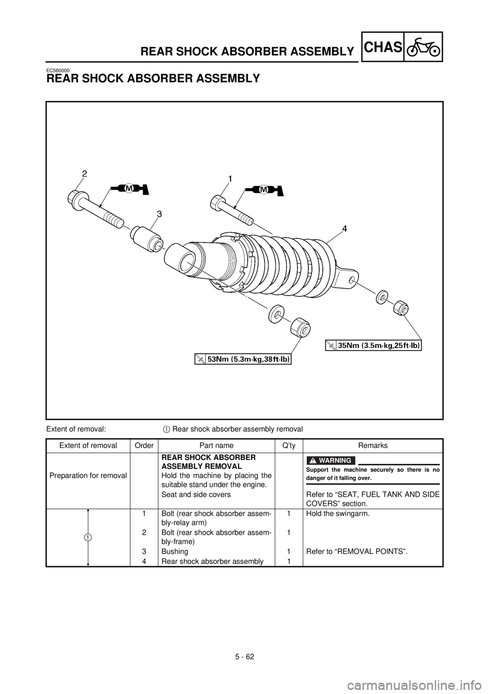
CHASREAR SHOCK ABSORBER ASSEMBLY
EC580000
REAR SHOCK ABSORBER ASSEMBLY
Extent of removal:1 Rear shock absorber assembly removal
Extent of removal Order Part name Q’ty Remarks
Preparation for removalREAR SHOCK ABSORBER
ASSEMBLY REMOVAL
Hold the machine by placing the
suitable stand under the engine.
WARNING
Support the machine securely so there is nodanger of it falling over.
Seat and side covers Refer to “SEAT, FUEL TANK AND SIDE
COVERS” section.
1 Bolt (rear shock absorber assem-
bly-relay arm)1 Hold the swingarm.
2 Bolt (rear shock absorber assem-
bly-frame)1
3 Bushing 1 Refer to “REMOVAL POINTS”.
4 Rear shock absorber assembly 1
1