air filter YAMAHA TTR50 2006 Owners Manual
[x] Cancel search | Manufacturer: YAMAHA, Model Year: 2006, Model line: TTR50, Model: YAMAHA TTR50 2006Pages: 390, PDF Size: 9.69 MB
Page 27 of 390
GEN
INFO
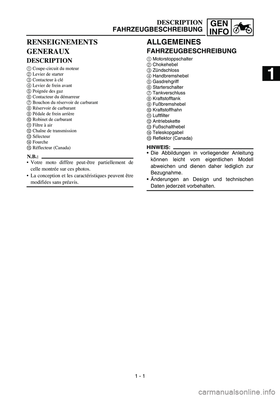
ALLGEMEINES
FAHRZEUGBESCHREIBUNG
1 Motorstoppschalter
2 Chokehebel
3 Zündschloss
4 Handbremshebel
5 Gasdrehgriff
6 Starterschalter
7 Tankverschluss
8 Kraftstofftank
9 Fußbremshebel
0 Kraftstoffhahn
A Luftfilter
B Antriebskette
C Fußschalthebel
D Teleskopgabel
E Reflektor (Canada)
HINWEIS:
Die Abbildungen in vorliegender Anleitung
können leicht vom eigentlichen Modell
abweichen und dienen daher lediglich zur
Bezugnahme.
Änderungen an Design und technischen
Daten jederzeit vorbehalten.
DESCRIPTION
FAHRZEUGBESCHREIBUNG
RENSEIGNEMENTS
GENERAUX
DESCRIPTION
1 Coupe-circuit du moteur
2 Levier de starter
3 Contacteur à clé
4 Levier de frein avant
5 Poignée des gaz
6 Contacteur du démarreur
7 Bouchon du réservoir de carburant
8 Réservoir de carburant
9 Pédale de frein arrière
0 Robinet de carburant
A Filtre à air
B Chaîne de transmission
C Sélecteur
D Fourche
E Réflecteur (Canada)
N.B.:
Votre moto diffère peut-être partiellement de
celle montrée sur ces photos.
La conception et les caractéristiques peuvent être
modifiées sans préavis.
1 - 1
1
2
3
4
5
6
Page 45 of 390
GEN
INFO
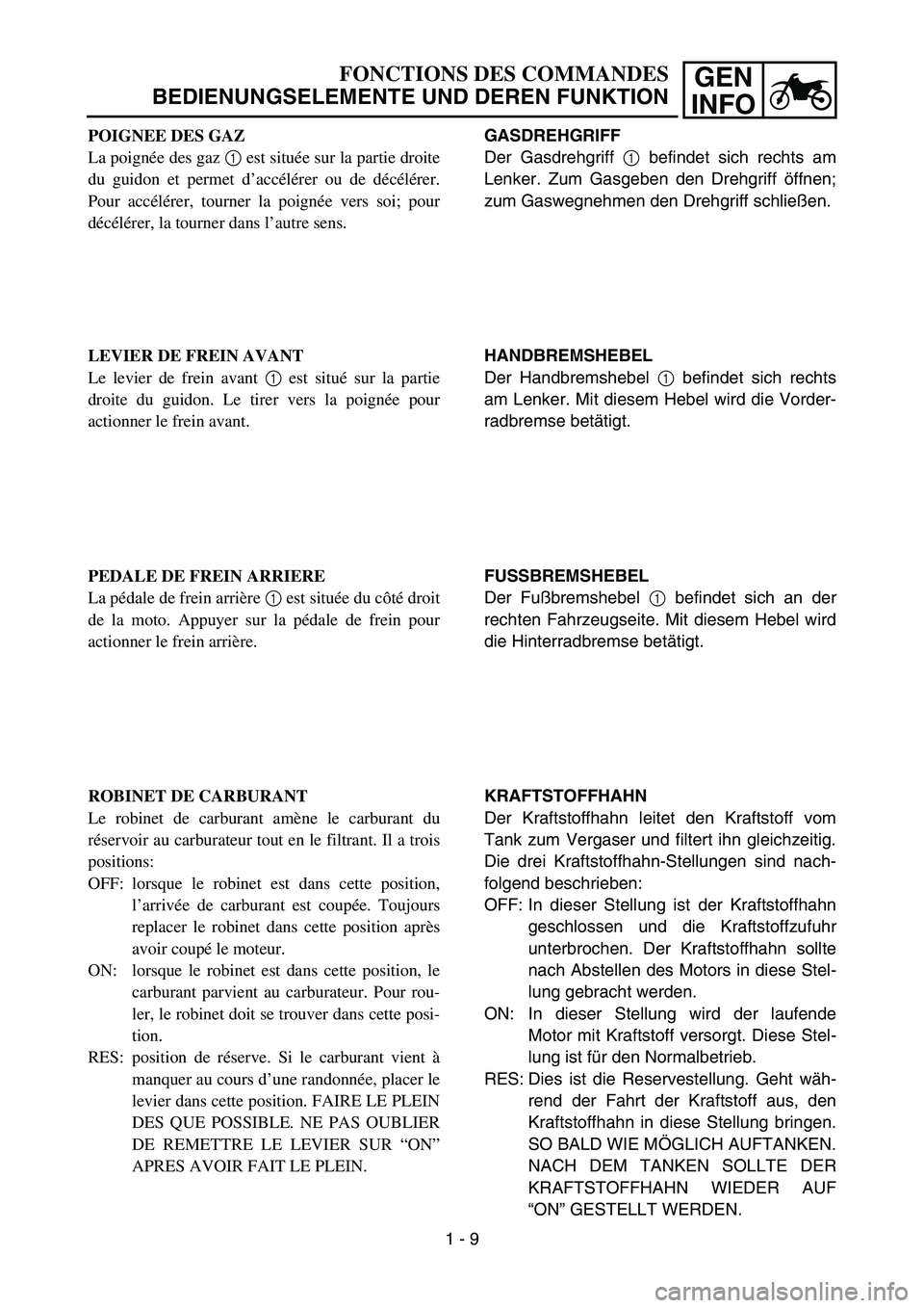
GASDREHGRIFF
Der Gasdrehgriff 1 befindet sich rechts am
Lenker. Zum Gasgeben den Drehgriff öffnen;
zum Gaswegnehmen den Drehgriff schlie ßen.
HANDBREMSHEBEL
Der Handbremshebel 1 befindet sich rechts
am Lenker. Mit diesem Hebel wird die Vorder-
radbremse bet ätigt.
FUSSBREMSHEBEL
Der Fu ßbremshebel 1 befindet sich an der
rechten Fahrzeugseite. Mit diesem Hebel wird
die Hinterradbremse bet ätigt.
KRAFTSTOFFHAHN
Der Kraftstoffhahn leitet den Kraftstoff vom
Tank zum Vergaser und filtert ihn gleichzeitig.
Die drei Kraftstoffhahn-Stellungen sind nach-
folgend beschrieben:
OFF: In dieser Stellung ist der Kraftstoffhahn geschlossen und die Kraftstoffzufuhr
unterbrochen. Der Kraftstoffhahn sollte
nach Abstellen des Motors in diese Stel-
lung gebracht werden.
ON: In dieser Stellung wird der laufende Motor mit Kraftstoff versorgt. Diese Stel-
lung ist f ür den Normalbetrieb.
RES: Dies ist die Reservestellung. Geht w äh-
rend der Fahrt der Kraftstoff aus, den
Kraftstoffhahn in diese Stellung bringen.
SO BALD WIE M ÖGLICH AUFTANKEN.
NACH DEM TANKEN SOLLTE DER
KRAFTSTOFFHAHN WIEDER AUF
“ ON ” GESTELLT WERDEN.
FONCTIONS DES COMMANDES
BEDIENUNGSELEMENTE UND DEREN FUNKTION
POIGNEE DES GAZ
La poign ée des gaz 1 est situ ée sur la partie droite
du guidon et permet d ’acc élé rer ou de d écélé rer.
Pour acc élé rer, tourner la poign ée vers soi; pour
d écélé rer, la tourner dans l ’autre sens.
LEVIER DE FREIN AVANT
Le levier de frein avant 1 est situ é sur la partie
droite du guidon. Le tirer vers la poign ée pour
actionner le frein avant.
PEDALE DE FREIN ARRIERE
La p édale de frein arri ère 1 est situ ée du c ôté droit
de la moto. Appuyer sur la p édale de frein pour
actionner le frein arri ère.
ROBINET DE CARBURANT
Le robinet de carburant am ène le carburant du
r é servoir au carburateur tout en le filtrant. Il a trois
positions:
OFF: lorsque le robinet est dans cette position, l’ arriv ée de carburant est coup ée. Toujours
replacer le robinet dans cette position apr ès
avoir coup é le moteur.
ON: lorsque le robinet est dans cette position, le carburant parvient au carburateur. Pour rou-
ler, le robinet doit se trouver dans cette posi-
tion.
RES: position de r éserve. Si le carburant vient à
manquer au cours d ’une randonn ée, placer le
levier dans cette position. FAIRE LE PLEIN
DES QUE POSSIBLE. NE PAS OUBLIER
DE REMETTRE LE LEVIER SUR “ON ”
APRES AVOIR FAIT LE PLEIN.
1 - 9
Page 57 of 390
SPEC
2 - 2
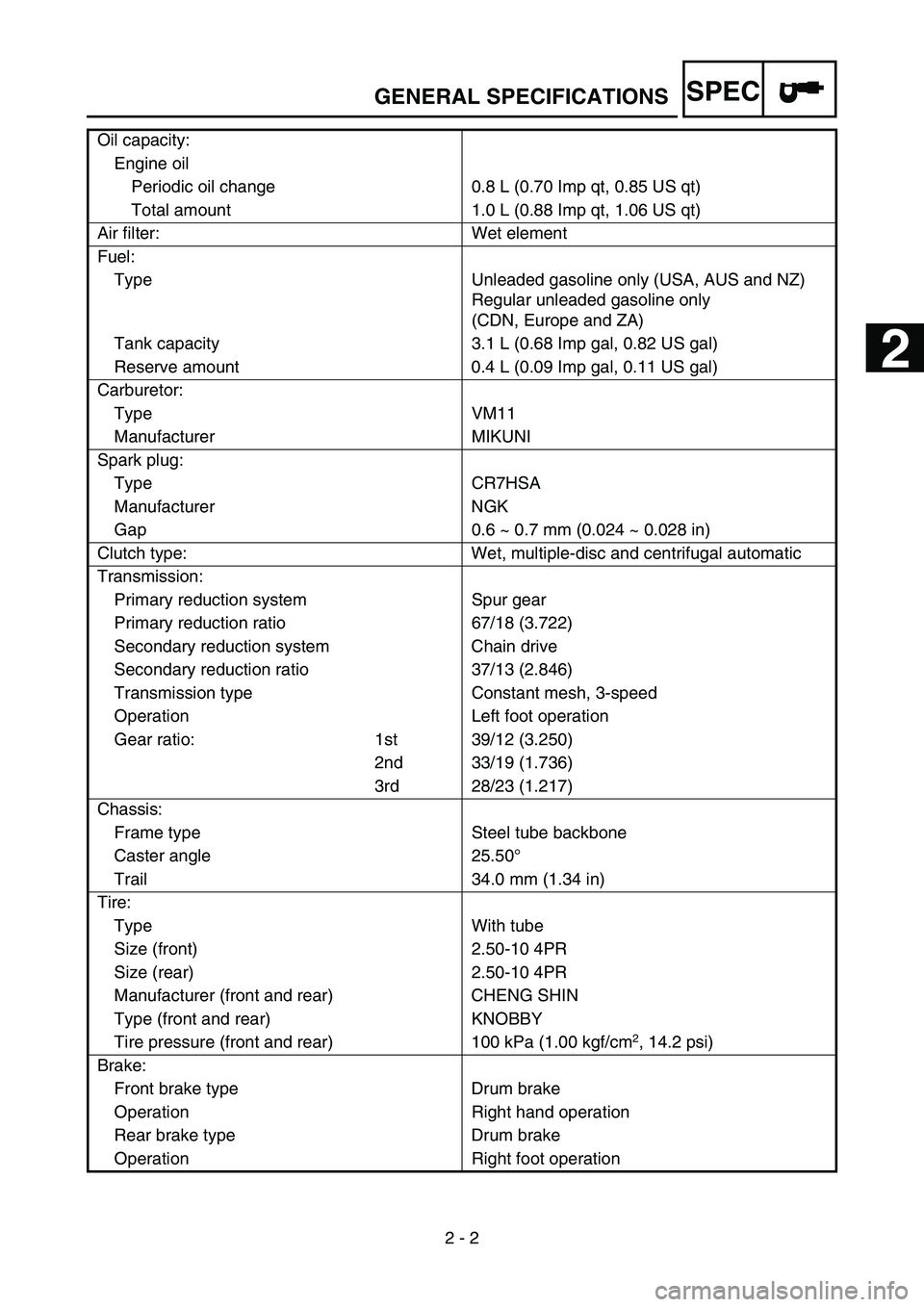
Oil capacity:
Engine oil Periodic oil change 0.8 L (0.70 Imp qt, 0.85 US qt)
Total amount 1.0 L (0.88 Imp qt, 1.06 US qt)
Air filter: Wet element
Fuel: Type Unleaded gasoline only (USA, AUS and NZ) Regular unleaded gasoline only
(CDN, Europe and ZA)
Tank capacity 3.1 L (0.68 Imp gal, 0.82 US gal)
Reserve amount 0.4 L (0.09 Imp gal, 0.11 US gal)
Carburetor: Type VM11
Manufacturer MIKUNI
Spark plug: Type CR7HSA
Manufacturer NGK
Gap 0.6 ~ 0.7 mm (0.024 ~ 0.028 in)
Clutch type: Wet, multiple-disc and centrifugal automatic
Transmission: Primary reduction system Spur gear
Primary reduction ratio 67/18 (3.722)
Secondary reduction system Chain drive
Secondary reduction ratio 37/13 (2.846)
Transmission type Constant mesh, 3-speed
Operation Left foot operation
Gear ratio: 1st 39/12 (3.250) 2nd 33/19 (1.736)
3rd 28/23 (1.217)
Chassis: Frame type Steel tube backbone
Caster angle 25.50 °
Trail 34.0 mm (1.34 in)
Tire: Type With tube
Size (front) 2.50-10 4PR
Size (rear) 2.50-10 4PR
Manufacturer (front and rear) CHENG SHIN
Type (front and rear) KNOBBY
Tire pressure (front and rear) 100 kPa (1.00 kgf/cm
2, 14.2 psi)
Brake: Front brake type Drum brake
Operation Right hand operation
Rear brake type Drum brake
Operation Right foot operation
GENERAL SPECIFICATIONS
1
2
3
4
5
6
Page 64 of 390
SPEC
2 - 9
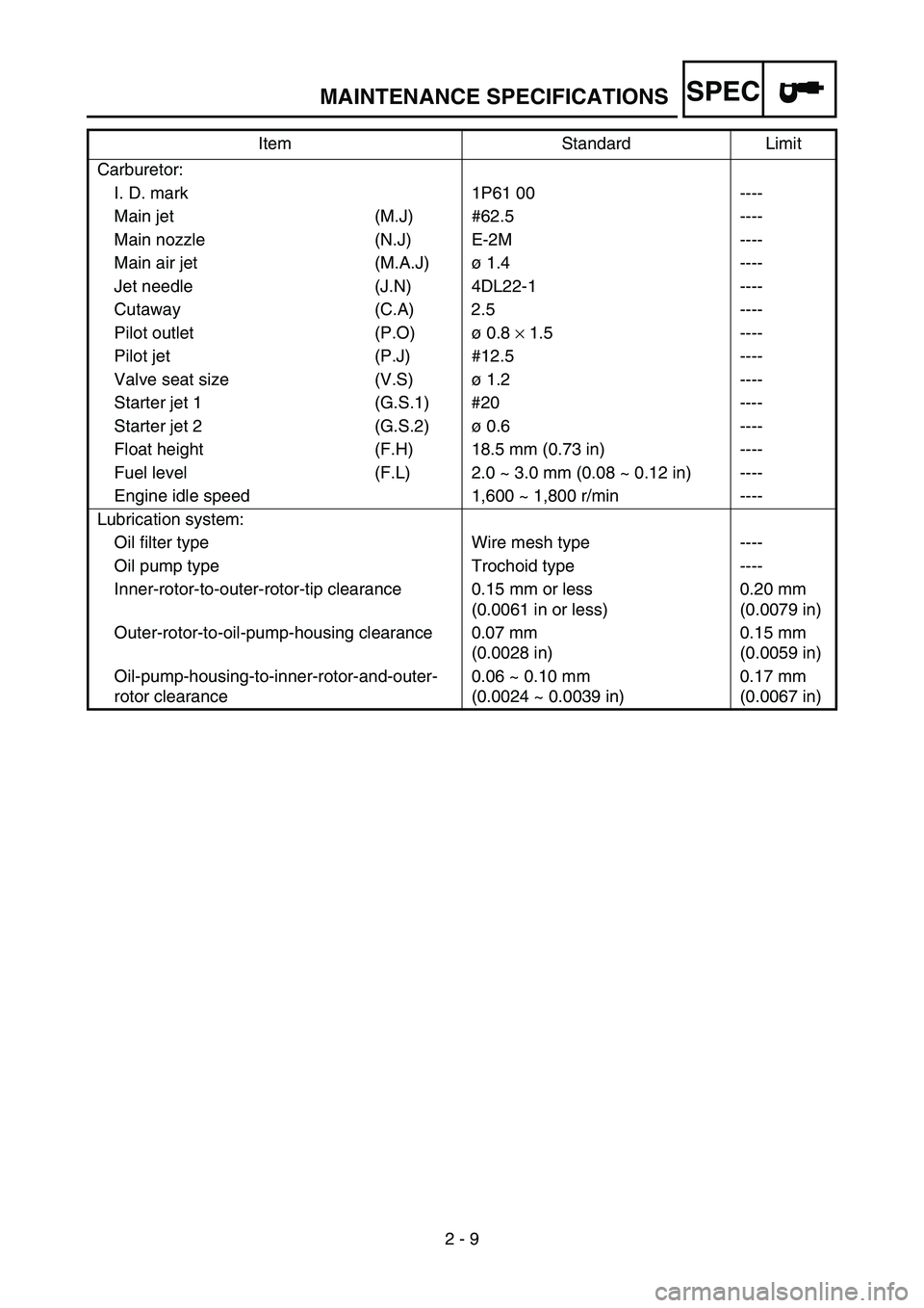
Carburetor:
I. D. mark 1P61 00 ----
Main jet (M.J) #62.5 ----
Main nozzle (N.J) E-2M ----
Main air jet (M.A.J) ø 1.4 ----
Jet needle (J.N) 4DL22-1 ----
Cutaway (C.A) 2.5 ----
Pilot outlet (P.O) ø 0.8 × 1.5 ----
Pilot jet (P.J) #12.5 ----
Valve seat size (V.S) ø 1.2 ----
Starter jet 1 (G.S.1) #20 ----
Starter jet 2 (G.S.2) ø 0.6 ----
Float height (F.H) 18.5 mm (0.73 in) ----
Fuel level (F.L) 2.0 ~ 3.0 mm (0.08 ~ 0.12 in) ----
Engine idle speed 1,600 ~ 1,800 r/min ----
Lubrication system: Oil filter type Wire mesh type ----
Oil pump type Trochoid type ----
Inner-rotor-to-outer-rotor-tip clearance 0.15 mm or less (0.0061 in or less)0.20 mm
(0.0079 in)
Outer-rotor-to-oil-pump-housing clearance 0.07 mm (0.0028 in)0.15 mm
(0.0059 in)
Oil-pump-housing-to-inner-rotor-and-outer-
rotor clearance 0.06 ~ 0.10 mm
(0.0024 ~ 0.0039 in)0.17 mm
(0.0067 in)
Item Standard Limit
MAINTENANCE SPECIFICATIONS
Page 65 of 390
SPEC
2 - 10
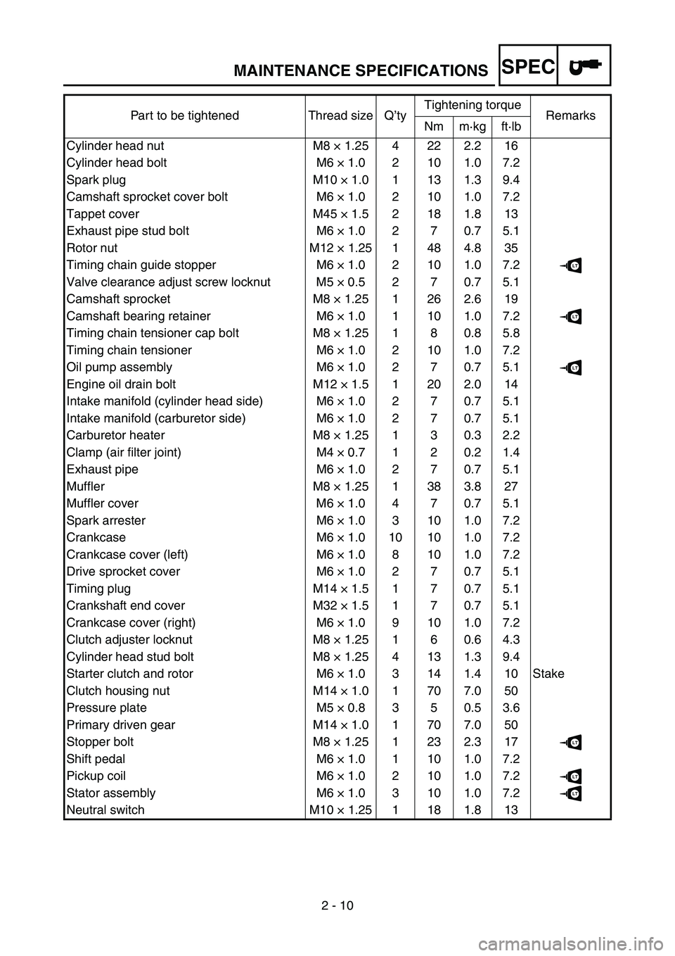
Part to be tightened Thread size Q
’ty Tightening torque
Remarks
Nm m ·kg ft ·lb
Cylinder head nut M8 × 1.25 4 22 2.2 16
Cylinder head bolt M6 × 1.0 2 10 1.0 7.2
Spark plug M10 × 1.0 1 13 1.3 9.4
Camshaft sprocket cover bolt M6 × 1.0 2 10 1.0 7.2
Tappet cover M45 × 1.5 2 18 1.8 13
Exhaust pipe stud bolt M6 × 1.0 2 7 0.7 5.1
Rotor nut M12 × 1.25 1 48 4.8 35
Timing chain guide stopper M6 × 1.0 2 10 1.0 7.2
LT
Valve clearance adjust screw locknut M5 × 0.5 2 7 0.7 5.1
Camshaft sprocket M8 × 1.25 1 26 2.6 19
Camshaft bearing retainer M6 × 1.0 1 10 1.0 7.2
LT
Timing chain tensioner cap bolt M8 × 1.25 1 8 0.8 5.8
Timing chain tensioner M6 × 1.0 2 10 1.0 7.2
Oil pump assembly M6 × 1.0 2 7 0.7 5.1
LT
Engine oil drain bolt M12 × 1.5 1 20 2.0 14
Intake manifold (cylinder head side) M6 × 1.0 2 7 0.7 5.1
Intake manifold (carburetor side) M6 × 1.0 2 7 0.7 5.1
Carburetor heater M8 × 1.25 1 3 0.3 2.2
Clamp (air filter joint) M4 × 0.7 1 2 0.2 1.4
Exhaust pipe M6 × 1.0 2 7 0.7 5.1
Muffler M8 × 1.25 1 38 3.8 27
Muffler cover M6 × 1.0 4 7 0.7 5.1
Spark arrester M6 × 1.0 3 10 1.0 7.2
Crankcase M6 × 1.0 10 10 1.0 7.2
Crankcase cover (left) M6 × 1.0 8 10 1.0 7.2
Drive sprocket cover M6 × 1.0 2 7 0.7 5.1
Timing plug M14 × 1.5 1 7 0.7 5.1
Crankshaft end cover M32 × 1.5 1 7 0.7 5.1
Crankcase cover (right) M6 × 1.0 9 10 1.0 7.2
Clutch adjuster locknut M8 × 1.25 1 6 0.6 4.3
Cylinder head stud bolt M8 × 1.25 4 13 1.3 9.4
Starter clutch and rotor M6 × 1.0 3 14 1.4 10 Stake
Clutch housing nut M14 × 1.0 1 70 7.0 50
Pressure plate M5 × 0.8 3 5 0.5 3.6
Primary driven gear M14 × 1.0 1 70 7.0 50
Stopper bolt M8 × 1.25 1 23 2.3 17
LT
Shift pedal M6 × 1.0 1 10 1.0 7.2
Pickup coil M6 × 1.0 2 10 1.0 7.2
LT
Stator assembly M6 × 1.0 3 10 1.0 7.2LT
Neutral switch M10 × 1.25 1 18 1.8 13
MAINTENANCE SPECIFICATIONS
Page 106 of 390
2 - 18
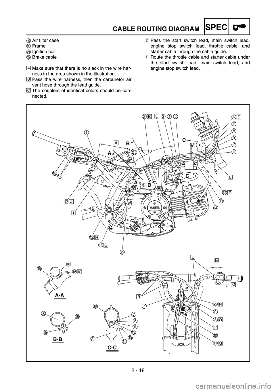
SPECCABLE ROUTING DIAGRAM
IAir filter case
J Frame
K Ignition coil
L Brake cable
È Make sure that there is no slack in the wire har-
ness in the area shown in the illustration.
É Pass the wire harness, then the carburetor air
vent hose through the lead guide.
Ê The couplers of identical colors should be con-
nected. Ë
Pass the start switch lead, main switch lead,
engine stop switch lead, throttle cable, and
starter cable through the cable guide.
Ì Route the throttle cable and starter cable under
the start switch lead, main switch lead, and
engine stop switch lead.
2
É
BÍ
B Ñ
BÏ
F Î
LÕ
\b
8 \b
×
0
\f Ø
E
E Ò 6
\f
7
8
\b
0
\f
C
D
H
H
7
J
I
I
K 8
7
\b
C
0
\f
E H
G 345
Ê
Ì
Ð
ÙÓ
Ô
Ô
È
B
A C
C
B
A
B-B
A-A
C-C
1
Page 107 of 390
2 - 18
SPEC
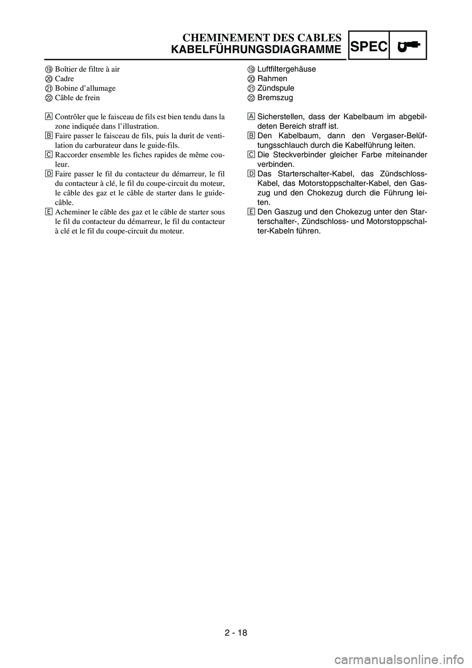
ILuftfiltergeh
äuse
J Rahmen
K Z
ündspule
L Bremszug
È Sicherstellen, dass der Kabelbaum im abgebil-
deten Bereich straff ist.
É Den Kabelbaum, dann den Vergaser-Bel
üf-
tungsschlauch durch die Kabelf ührung leiten.
Ê Die Steckverbinder gleicher Farbe miteinander
verbinden.
Ë Das Starterschalter-Kabel, das Z
ündschloss-
Kabel, das Motorstoppschalter-Kabel, den Gas-
zug und den Chokezug durch die F ührung lei-
ten.
Ì Den Gaszug und den Chokezug unter den Star-
terschalter-, Z
ündschloss- und Motorstoppschal-
ter-Kabeln f ühren.
CHEMINEMENT DES CABLES
KABELF ÜHRUNGSDIAGRAMME
I Boîtier de filtre à air
J Cadre
K Bobine d ’allumage
L Câble de frein
È Contr ôler que le faisceau de fils est bien tendu dans la
zone indiqu ée dans l ’illustration.
É Faire passer le faisceau de fils, puis la durit de venti-
lation du carburateur dans le guide-fils.
Ê Raccorder ensemble les fiches rapides de m ême cou-
leur.
Ë Faire passer le fil du contacteur du d émarreur, le fil
du contacteur à cl é, le fil du coupe-circuit du moteur,
le c âble des gaz et le c âble de starter dans le guide-
c âble.
Ì Acheminer le c âble des gaz et le c âble de starter sous
le fil du contacteur du d émarreur, le fil du contacteur
à cl é et le fil du coupe-circuit du moteur.
Page 110 of 390
2 - 20
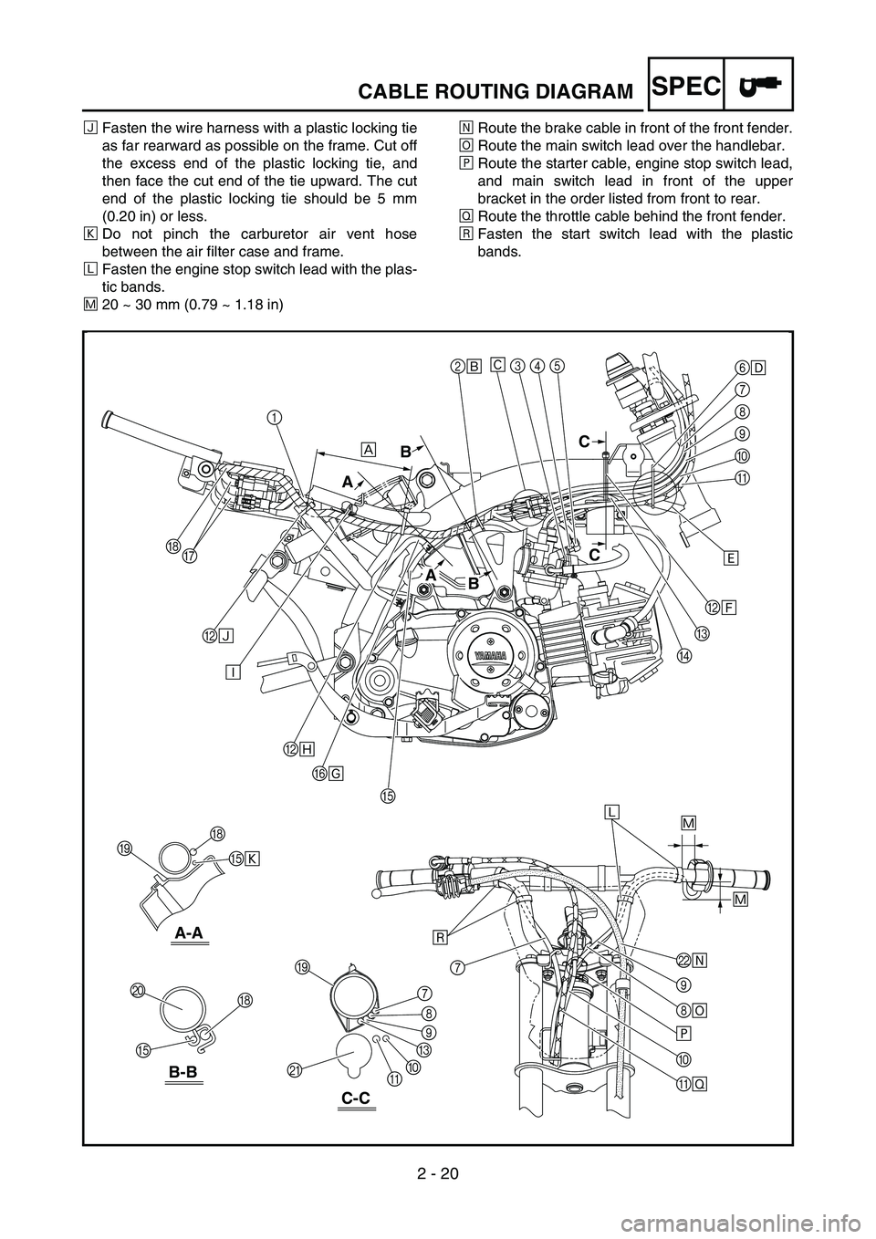
SPECCABLE ROUTING DIAGRAM
ÑFasten the wire harness with a plastic locking tie
as far rearward as possible on the frame. Cut off
the excess end of the plastic locking tie, and
then face the cut end of the tie upward. The cut
end of the plastic locking tie should be 5 mm
(0.20 in) or less.
Ò Do not pinch the carburetor air vent hose
between the air filter case and frame.
Ó Fasten the engine stop switch lead with the plas-
tic bands.
Ô 20 ~ 30 mm (0.79 ~ 1.18 in) Õ
Route the brake cable in front of the front fender.
Ö Route the main switch lead over the handlebar.
× Route the starter cable, engine stop switch lead,
and main switch lead in front of the upper
bracket in the order listed from front to rear.
Ø Route the throttle cable behind the front fender.
Ù Fasten the start switch lead with the plastic
bands.
2
É
BÍ
B Ñ
BÏ
F Î
LÕ
\b
8 \b
×
0
\f Ø
E
E Ò 6
\f
7
8
\b
0
\f
C
D
H
H
7
J
I
I
K 8
7
\b
C
0
\f
E H
G 345
Ê
Ì
Ð
ÙÓ
Ô
Ô
È
B
A C
C
B
A
B-B
A-A
C-C
1
Page 111 of 390
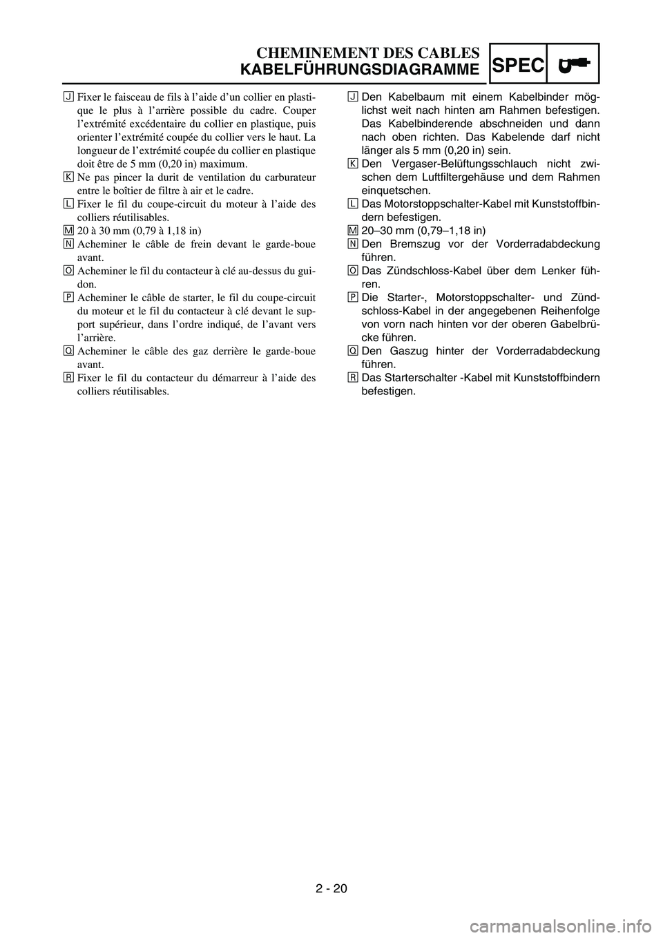
2 - 20
SPEC
ÑDen Kabelbaum mit einem Kabelbinder m
ög-
lichst weit nach hinten am Rahmen befestigen.
Das Kabelbinderende abschneiden und dann
nach oben richten. Das Kabelende darf nicht
l ä nger als 5 mm (0,20 in) sein.
Ò Den Vergaser-Bel
üftungsschlauch nicht zwi-
schen dem Luftfiltergeh äuse und dem Rahmen
einquetschen.
Ó Das Motorstoppschalter-Kabel mit Kunststoffbin-
dern befestigen.
Ô 20
–30 mm (0,79 –1,18 in)
Õ Den Bremszug vor der Vorderradabdeckung
f
ü hren.
Ö Das Z
ündschloss-Kabel über dem Lenker f üh-
ren.
× Die Starter-, Motorstoppschalter- und Z
ünd-
schloss-Kabel in der angegebenen Reihenfolge
von vorn nach hinten vor der oberen Gabelbr ü-
cke f ühren.
Ø Den Gaszug hinter der Vorderradabdeckung
f
ü hren.
Ù Das Starterschalter -Kabel mit Kunststoffbindern
befestigen.
CHEMINEMENT DES CABLES
KABELF ÜHRUNGSDIAGRAMME
Ñ Fixer le faisceau de fils à l ’aide d ’un collier en plasti-
que le plus à l ’arri ère possible du cadre. Couper
l ’ extr émit é exc édentaire du collier en plastique, puis
orienter l ’extr émit é coup ée du collier vers le haut. La
longueur de l ’extr émit é coup ée du collier en plastique
doit être de 5 mm (0,20 in) maximum.
Ò Ne pas pincer la durit de ventilation du carburateur
entre le bo îtier de filtre à air et le cadre.
Ó Fixer le fil du coupe-circuit du moteur à l ’aide des
colliers r éutilisables.
Ô 20 à 30 mm (0,79 à 1,18 in)
Õ Acheminer le c âble de frein devant le garde-boue
avant.
Ö Acheminer le fil du contacteur à cl é au-dessus du gui-
don.
× Acheminer le c âble de starter, le fil du coupe-circuit
du moteur et le fil du contacteur à cl é devant le sup-
port sup érieur, dans l ’ordre indiqu é, de l ’avant vers
l ’ arri ère.
Ø Acheminer le c âble des gaz derri ère le garde-boue
avant.
Ù Fixer le fil du contacteur du d émarreur à l ’aide des
colliers r éutilisables.
Page 118 of 390
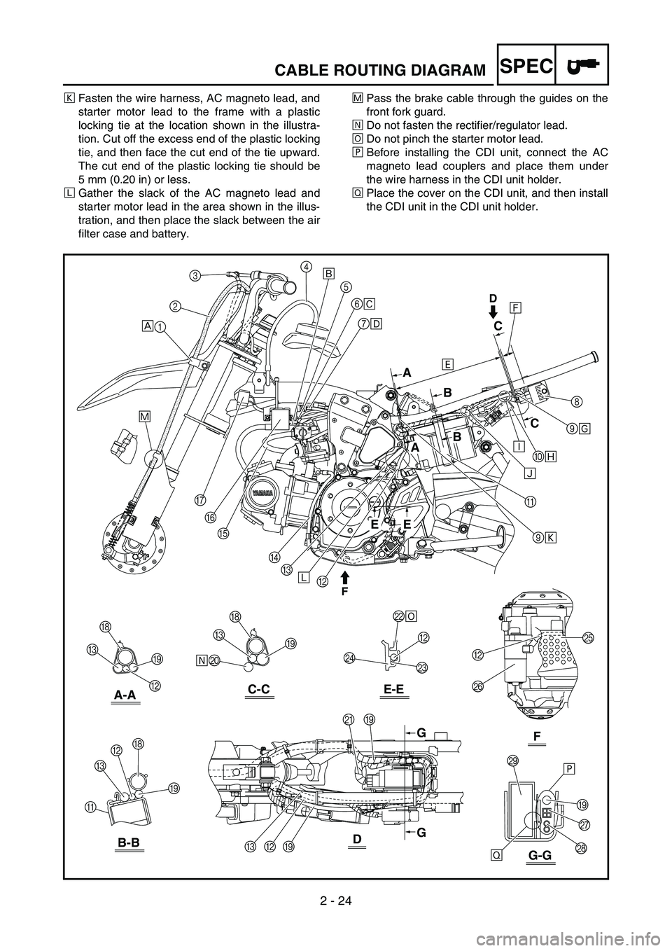
2 - 24
SPECCABLE ROUTING DIAGRAM
ÒFasten the wire harness, AC magneto lead, and
starter motor lead to the frame with a plastic
locking tie at the location shown in the illustra-
tion. Cut off the excess end of the plastic locking
tie, and then face the cut end of the tie upward.
The cut end of the plastic locking tie should be
5 mm (0.20 in) or less.
Ó Gather the slack of the AC magneto lead and
starter motor lead in the area shown in the illus-
tration, and then place the slack between the air
filter case and battery. Ô
Pass the brake cable through the guides on the
front fork guard.
Õ Do not fasten the rectifier/regulator lead.
Ö Do not pinch the starter motor lead.
× Before installing the CDI unit, connect the AC
magneto lead couplers and place them under
the wire harness in the CDI unit holder.
Ø Place the cover on the CDI unit, and then install
the CDI unit in the CDI unit holder.
RES
OFF
FUEL
A
EE
A
B C
C
B
G
G
D
F
È1
ÕJ
2
3
4
5
8
\f
6
Ê
\bÎ
0 Ï
\b Ò
L \b
B
C
D
E
F
G
H I
B I
H
C
NB
M B
P O
R Q
I
S
I
K
I
B
C
I
H
B
C
\f C
Ó
×
Ø
Ô
ÐÑ
Ì
Í
7 \f
É
C-C
E-EA-A
B-B
G-G
D
F