replacement YAMAHA TTR50 2006 Owners Manual
[x] Cancel search | Manufacturer: YAMAHA, Model Year: 2006, Model line: TTR50, Model: YAMAHA TTR50 2006Pages: 390, PDF Size: 9.69 MB
Page 32 of 390
1 - 4
GEN
INFO
IMPORTANT INFORMATION
EC132000
ALL REPLACEMENT PARTS
1. We recommend to use Yamaha genuine
parts for all replacements. Use oil and/or
grease recommended by Yamaha for
assembly and adjustment.
EC133000
GASKETS, OIL SEALS AND O-RINGS
1. All gaskets, oil seals, and O-rings shouldbe replaced when an engine is overhauled.
All gasket surfaces, oil seal lips, and O-
rings must be cleaned.
2. Properly oil all mating parts and bearings
during reassembly. Apply grease to the oil
seal lips.
EC134000
LOCK WASHERS/PLATES AND COTTER
PINS
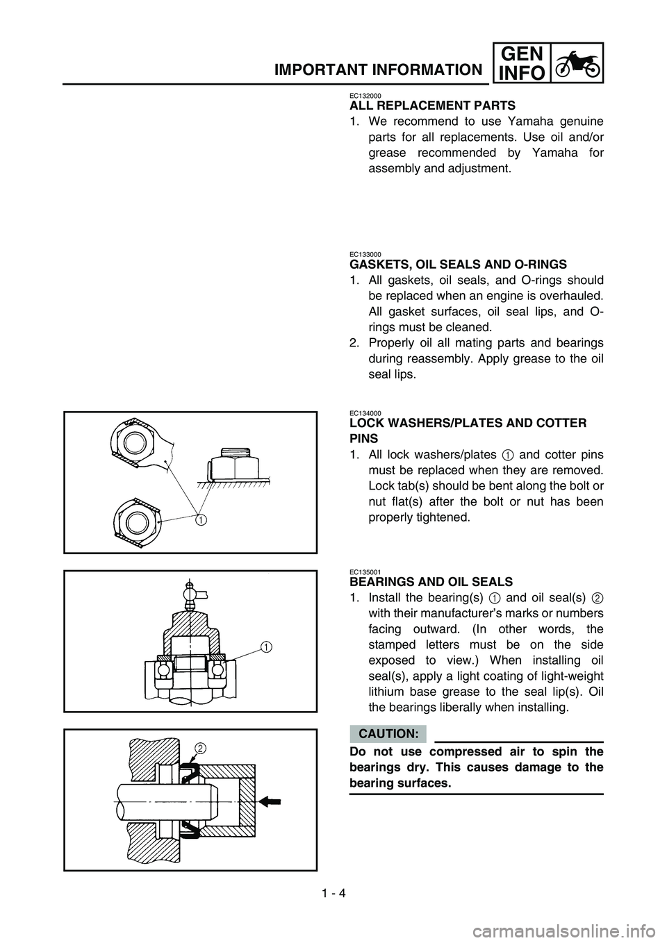
1. All lock washers/plates 1 and cotter pins
must be replaced when they are removed.
Lock tab(s) should be bent along the bolt or
nut flat(s) after the bolt or nut has been
properly tightened.
EC135001
BEARINGS AND OIL SEALS
1. Install the bearing(s) 1 and oil seal(s) 2
with their manufacturer ’s marks or numbers
facing outward. (In other words, the
stamped letters must be on the side
exposed to view.) When installing oil
seal(s), apply a light coating of light-weight
lithium base grease to the seal lip(s). Oil
the bearings liberally when installing.
CAUTION:
Do not use compressed air to spin the
bearings dry. This causes damage to the
bearing surfaces.
Page 140 of 390
3 - 9
INSPADJENGINE OIL LEVEL INSPECTION/
ENGINE OIL REPLACEMENT
5. Install:
Oil filler cap
6. Start the engine and let it warm up for sev-
eral minutes.
7. Turn off the engine and inspect the oil level once again.
NOTE:
Wait a few minutes until the oil settles before
inspecting the oil level.
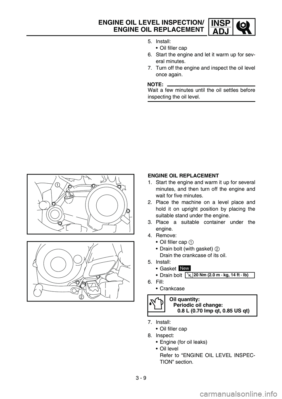
ENGINE OIL REPLACEMENT
1. Start the engine and warm it up for severalminutes, and then turn off the engine and
wait for five minutes.
2. Place the machine on a level place and hold it on upright position by placing the
suitable stand under the engine.
3. Place a suitable container under the engine.
4. Remove:
Oil filler cap 1
Drain bolt (with gasket) 2
Drain the crankcase of its oil.
5. Install: Gasket
Drain bolt
6. Fill: Crankcase
7. Install: Oil filler cap
8. Inspect: Engine (for oil leaks)
Oil level
Refer to “ENGINE OIL LEVEL INSPEC-
TION ” section.
Oil quantity:
Periodic oil change: 0.8 L (0.70 Imp qt, 0.85 US qt)
1
2
New
T R..20 Nm (2.0 m · kg, 14 ft · lb)
Page 186 of 390
3 - 31
INSPADJ
FUSE INSPECTION
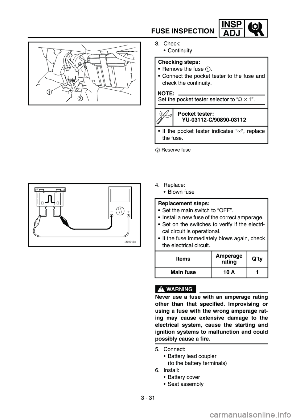
3. Check:
Continuity
2 Reserve fuse
Checking steps:
Remove the fuse 1
.
Connect the pocket tester to the fuse and
check the continuity.
NOTE:
Set the pocket tester selector to “Ω × 1 ”.
Pocket tester:
YU-03112-C/90890-03112
If the pocket tester indicates “∞ ”, replace
the fuse.
1 2
4. Replace:
Blown fuse
WARNING
Never use a fuse with an amperage rating
other than that specified. Improvising or
using a fuse with the wrong amperage rat-
ing may cause extensive damage to the
electrical system, cause the starting and
ignition systems to malfunction and could
possibly cause a fire.
5. Connect:
Battery lead coupler
(to the battery terminals)
6. Install: Battery cover
Seat assembly
Replacement steps:
Set the main switch to “OFF ”.
Install a new fuse of the correct amperage.
Set on the switches to verify if the electri-
cal circuit is operational.
If the fuse immediately blows again, check
the electrical circuit.
Items Amperage
rating Q
’ty
Main fuse 10 A 1
Page 282 of 390
4 - 48
ENGENGINE REMOVAL
(4)
NewNew
LS
T R..30 Nm (3.0 m • kg, 22 ft • Ib)
T R..30 Nm (3.0 m •
kg, 22 ft • Ib)
T R..30 Nm (3.0 m •
kg, 22 ft • Ib)
T R..30 Nm (3.0 m •
kg, 22 ft • Ib)
T R..48 Nm (4.8 m •
kg, 35 ft • Ib)
T R..7 Nm (0.7 m •
kg, 5.1 ft • Ib)
T R..10 Nm (1.0 m • kg, 7.2 ft • Ib)
(3)
10
4
1 6
2
9
3
11
7
5 8
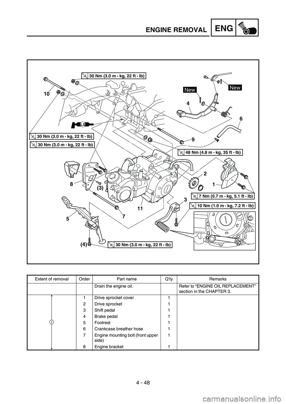
Extent of removal Order Part name Q
’ty Remarks
Drain the engine oil. Refer to “ENGINE OIL REPLACEMENT ”
section in the CHAPTER 3.
1 Drive sprocket cover 1
2 Drive sprocket 1
3 Shift pedal 1
4 Brake pedal 1
5 Footrest 1
6 Crankcase breather hose 1
7 Engine mounting bolt (front upper side) 1
8 Engine bracket 1
1
Page 288 of 390
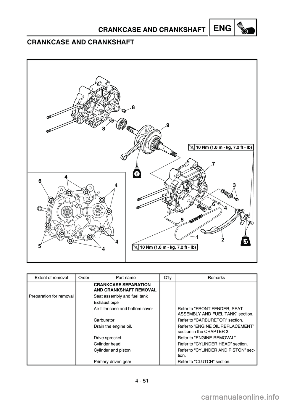
4 - 51
ENGCRANKCASE AND CRANKSHAFT
CRANKCASE AND CRANKSHAFT
E
T R..10 Nm (1.0 m • kg, 7.2 ft • Ib)
T R..10 Nm (1.0 m •
kg, 7.2 ft • Ib)
LT
4
4 3
4
4
5 6
7
9
8
8
12
5 6
4
Extent of removal Order Part name Q ’ty Remarks
CRANKCASE SEPARATION
AND CRANKSHAFT REMOVAL
Preparation for removal Seat assembly and fuel tank
Exhaust pipe
Air filter case and bottom cover Refer to “FRONT FENDER, SEAT
ASSEMBLY AND FUEL TANK ” section.
Carburetor Refer to “CARBURETOR ” section.
Drain the engine oil. Refer to “ENGINE OIL REPLACEMENT ”
section in the CHAPTER 3.
Drive sprocket Refer to “ENGINE REMOVAL ”.
Cylinder head Refer to “CYLINDER HEAD ” section.
Cylinder and piston Refer to “CYLINDER AND PISTON ” sec-
tion.
Primary driven gear Refer to “CLUTCH ” section.
Page 362 of 390
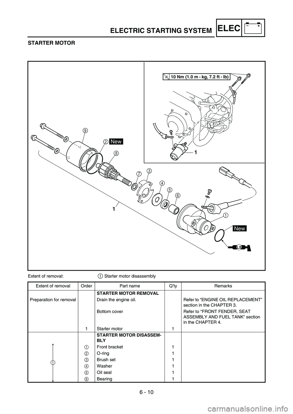
6 - 10
–+ELEC
STARTER MOTOR
1
3
45 6
8
2
\b
1
1
LS
New
New
T R..10 Nm (1.0 m •
kg, 7.2 ft • Ib)
7
Extent of removal:1 Starter motor disassembly
Extent of removal Order Part name Q ’ty Remarks
STARTER MOTOR REMOVAL
Preparation for removal Drain the engine oil. Refer to “ENGINE OIL REPLACEMENT ”
section in the CHAPTER 3.
Bottom cover Refer to “FRONT FENDER, SEAT
ASSEMBLY AND FUEL TANK ” section
in the CHAPTER 4.
1 Starter motor 1 STARTER MOTOR DISASSEM-
BLY
1 Front bracket 1
2 O-ring 1
3 Brush set 1
4 Washer 1
5 Oil seal 1
6 Bearing 1
1
ELECTRIC STARTING SYSTEM