YAMAHA TTR90 2000 Owners Manual
Manufacturer: YAMAHA, Model Year: 2000, Model line: TTR90, Model: YAMAHA TTR90 2000Pages: 287, PDF Size: 6.77 MB
Page 271 of 287
–+ELEC
SYSTEME D’ALLUMAGE
ZÜNDANLAGE
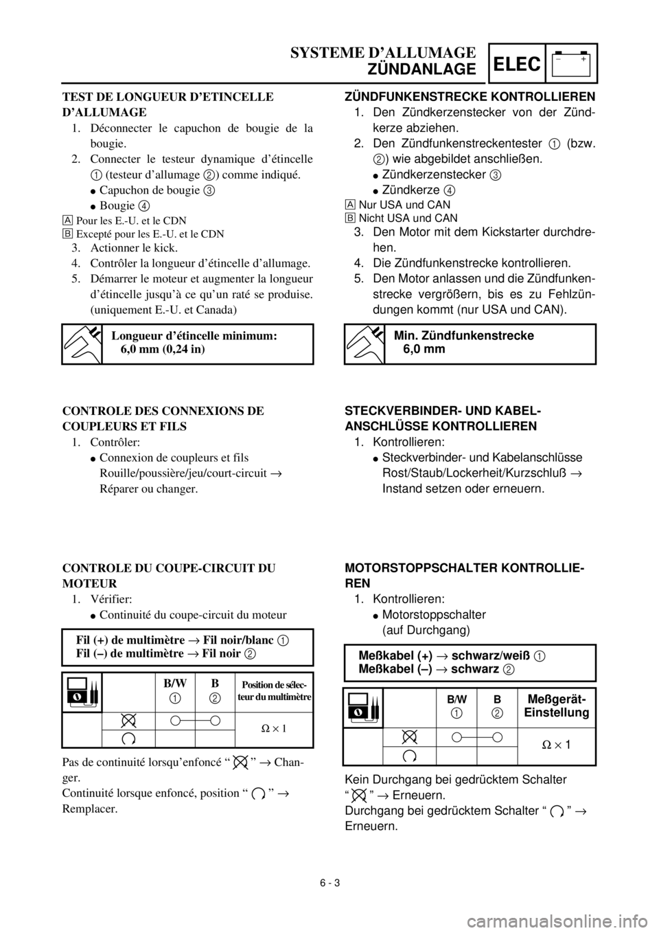
ZÜNDFUNKENSTRECKE KONTROLLIEREN
1. Den Zündkerzenstecker von der Zünd-
kerze abziehen.
2. Den Zündfunkenstreckentester
1
(bzw.
2
) wie abgebildet anschließen.
l
Zündkerzenstecker
3
l
Zündkerze
4
Nur USA und CAN
õ
Nicht USA und CAN
3. Den Motor mit dem Kickstarter durchdre-
hen.
4. Die Zündfunkenstrecke kontrollieren.
5. Den Motor anlassen und die Zündfunken-
strecke vergrößern, bis es zu Fehlzün-
dungen kommt (nur USA und CAN).
Min. Zündfunkenstrecke
6,0 mm
MOTORSTOPPSCHALTER KONTROLLIE-
REN
1. Kontrollieren:
l
Motorstoppschalter
(auf Durchgang)
Kein Durchgang bei gedrücktem Schalter
“”
®
Erneuern.
Durchgang bei gedrücktem Schalter “ ”
®
Erneuern.
Meßkabel (+)
®
schwarz/weiß
1
Meßkabel (–)
®
schwarz
2
B/W
1
B
2
Meßgerät-
Einstellung
W
´
1
TEST DE LONGUEUR D’ETINCELLE
D’ALLUMAGE
1. Déconnecter le capuchon de bougie de la
bougie.
2. Connecter le testeur dynamique d’étincelle
1 (testeur d’allumage 2) comme indiqué.
lCapuchon de bougie 3
lBougie 4
Pour les E.-U. et le CDN
õExcepté pour les E.-U. et le CDN
3. Actionner le kick.
4. Contrôler la longueur d’étincelle d’allumage.
5. Démarrer le moteur et augmenter la longueur
d’étincelle jusqu’à ce qu’un raté se produise.
(uniquement E.-U. et Canada)
Longueur d’étincelle minimum:
6,0 mm (0,24 in)
CONTROLE DES CONNEXIONS DE
COUPLEURS ET FILS
1. Contrôler:
lConnexion de coupleurs et fils
Rouille/poussière/jeu/court-circuit ®
Réparer ou changer.
CONTROLE DU COUPE-CIRCUIT DU
MOTEUR
1. Vérifier:
lContinuité du coupe-circuit du moteur
Pas de continuité lorsqu’enfoncé “ ” ® Chan-
ger.
Continuité lorsque enfoncé, position “ ” ®
Remplacer.Fil (+) de multimètre ® Fil noir/blanc 1
Fil (–) de multimètre ® Fil noir 2
B/W
1B
2Position de sélec-
teur du multimètre
W ´ 1
6 - 3
STECKVERBINDER- UND KABEL-
ANSCHLÜSSE KONTROLLIEREN
1. Kontrollieren:
lSteckverbinder- und Kabelanschlüsse
Rost/Staub/Lockerheit/Kurzschluß ®
Instand setzen oder erneuern.
Page 272 of 287
6 - 4
–+ELEC
IGNITION SYSTEM
EC626002
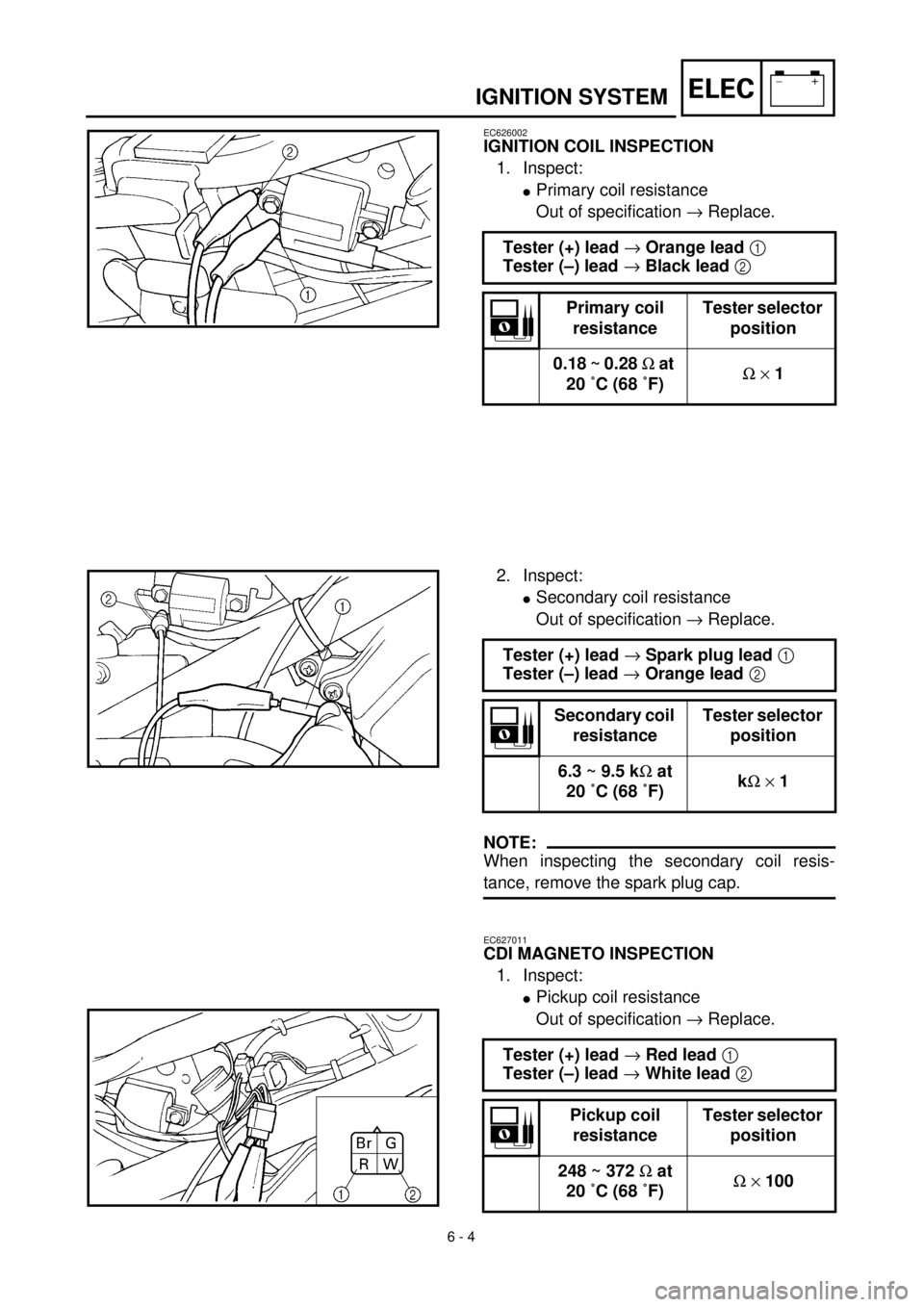
IGNITION COIL INSPECTION
1. Inspect:
l
Primary coil resistance
Out of specification
®
Replace.
Tester (+) lead
®
Orange lead
1
Tester (–) lead
®
Black lead
2
Primary coil
resistanceTester selector
position
0.18 ~ 0.28
W
at
20 ˚C (68 ˚F)
W
´
1
2. Inspect:
l
Secondary coil resistance
Out of specification
®
Replace.
NOTE:
When inspecting the secondary coil resis-
tance, remove the spark plug cap.
EC627011
CDI MAGNETO INSPECTION
1. Inspect:
lPickup coil resistance
Out of specification ® Replace. Tester (+) lead ® Spark plug lead 1
Tester (–) lead ® Orange lead 2
Secondary coil
resistanceTester selector
position
6.3 ~ 9.5 kW at
20 ˚C (68 ˚F)kW ´ 1
Tester (+) lead ® Red lead 1
Tester (–) lead ® White lead 2
Pickup coil
resistanceTester selector
position
248 ~ 372 W at
20 ˚C (68 ˚F)W ´ 100
Page 273 of 287
–+ELEC
SYSTEME D’ALLUMAGE
ZÜNDANLAGE
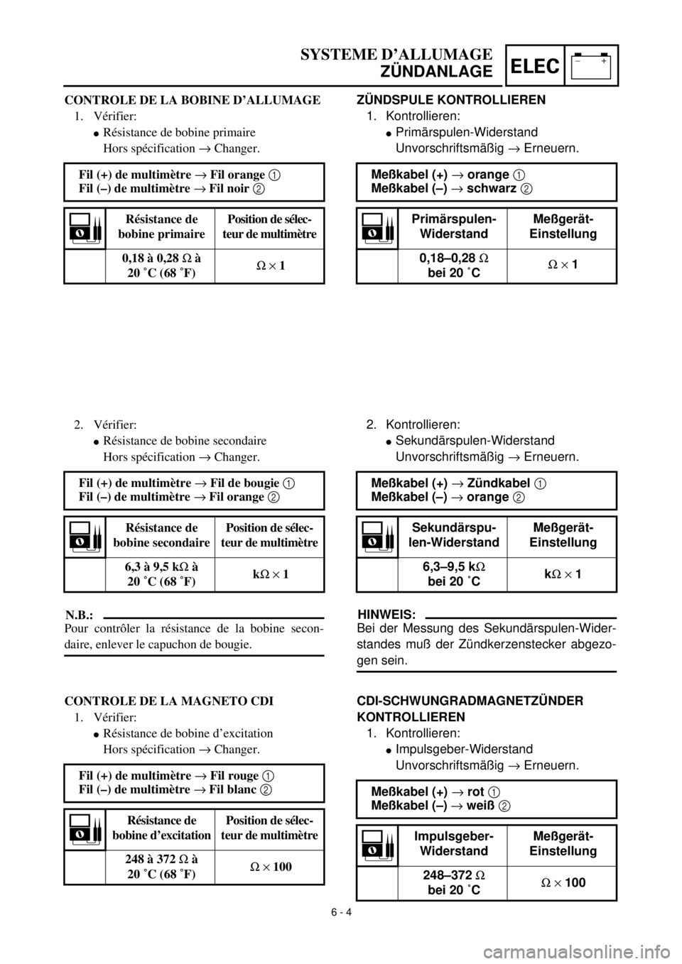
ZÜNDSPULE KONTROLLIEREN
1. Kontrollieren:
lPrimärspulen-Widerstand
Unvorschriftsmäßig ® Erneuern.
Meßkabel (+) ® orange 1
Meßkabel (–) ® schwarz 2
Primärspulen-
WiderstandMeßgerät-
Einstellung
0,18–0,28 W
bei 20 ˚CW ´ 1
CONTROLE DE LA BOBINE D’ALLUMAGE
1. Vérifier:
lRésistance de bobine primaire
Hors spécification ® Changer.
Fil (+) de multimètre ® Fil orange 1
Fil (–) de multimètre ® Fil noir 2
Résistance de
bobine primairePosition de sélec-
teur de multimètre
0,18 à 0,28 W à
20 ˚C (68 ˚F)W ´ 1
6 - 4
2. Vérifier:
lRésistance de bobine secondaire
Hors spécification ® Changer.
N.B.:
Pour contrôler la résistance de la bobine secon-
daire, enlever le capuchon de bougie.
CONTROLE DE LA MAGNETO CDI
1. Vérifier:
lRésistance de bobine d’excitation
Hors spécification ® Changer. Fil (+) de multimètre ® Fil de bougie 1
Fil (–) de multimètre ® Fil orange 2
Résistance de
bobine secondairePosition de sélec-
teur de multimètre
6,3 à 9,5 kW à
20 ˚C (68 ˚F)kW ´ 1
Fil (+) de multimètre ® Fil rouge 1
Fil (–) de multimètre ® Fil blanc 2
Résistance de
bobine d’excitationPosition de sélec-
teur de multimètre
248 à 372 W à
20 ˚C (68 ˚F)W ´ 100
2. Kontrollieren:
lSekundärspulen-Widerstand
Unvorschriftsmäßig ® Erneuern.
HINWEIS:
Bei der Messung des Sekundärspulen-Wider-
standes muß der Zündkerzenstecker abgezo-
gen sein.
CDI-SCHWUNGRADMAGNETZÜNDER
KONTROLLIEREN
1. Kontrollieren:
lImpulsgeber-Widerstand
Unvorschriftsmäßig ® Erneuern. Meßkabel (+) ® Zündkabel 1
Meßkabel (–) ® orange 2
Sekundärspu-
len-WiderstandMeßgerät-
Einstellung
6,3–9,5 kW
bei 20 ˚CkW ´ 1
Meßkabel (+) ® rot 1
Meßkabel (–) ® weiß 2
Impulsgeber-
WiderstandMeßgerät-
Einstellung
248–372 W
bei 20 ˚CW ´ 100
Page 274 of 287
6 - 5
–+ELECIGNITION SYSTEM
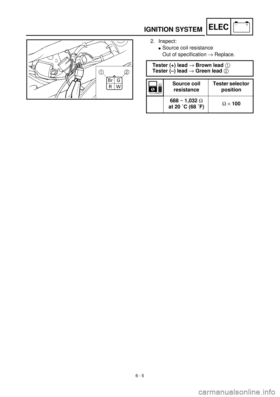
2. Inspect:
lSource coil resistance
Out of specification ® Replace.
Tester (+) lead ® Brown lead 1
Tester (–) lead ® Green lead 2
Source coil
resistanceTester selector
position
688 ~ 1,032 W
at 20 ˚C (68 ˚F)W ´ 100
Page 275 of 287

–+ELEC
SYSTEME D’ALLUMAGE
ZÜNDANLAGE
2. Kontrollieren:
lErregerspule-Widerstand
Unvorschriftsmäßig ® Erneuern.
Meßkabel (+) ® braun 1
Meßkabel (–) ® grün 2
Erregerspule-
WiderstandMeßgerät-
Einstellung
688–1.032 W
bei 20 ˚CW ´ 100
2. Vérifier:
lRésistance de bobine de source
Hors spécification ® Changer.
Fil (+) de multimètre ® Fil brun 1
Fil (–) de multimètre ® Fil vert 2
Résistance de
bobine de sourcePosition de sélec-
teur de multimètre
688 à 1.032 W à
20 ˚C (68 ˚F)W ´ 100
6 - 5
Page 276 of 287
–+ELEC
6 - 6
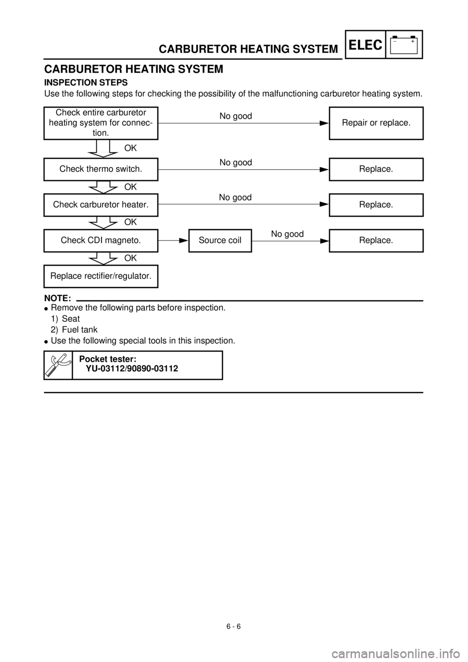
CARBURETOR HEATING SYSTEM
CARBURETOR HEATING SYSTEM
INSPECTION STEPS
Use the following steps for checking the possibility of the malfunctioning carburetor heating system.
NOTE:
lRemove the following parts before inspection.
1) Seat
2) Fuel tank
lUse the following special tools in this inspection.
Check entire carburetor
heating system for connec-
tion.Repair or replace.
Check thermo switch. Replace.
Check carburetor heater. Replace.
Check CDI magneto. Source coil Replace.
Replace rectifier/regulator.
Pocket tester:
YU-03112/90890-03112
OK
OK
OK
No good
No good
No good
No good
OK
Page 277 of 287
–+ELECSYSTEME DE RECHAUFFEMENT DU CARBURATEUR
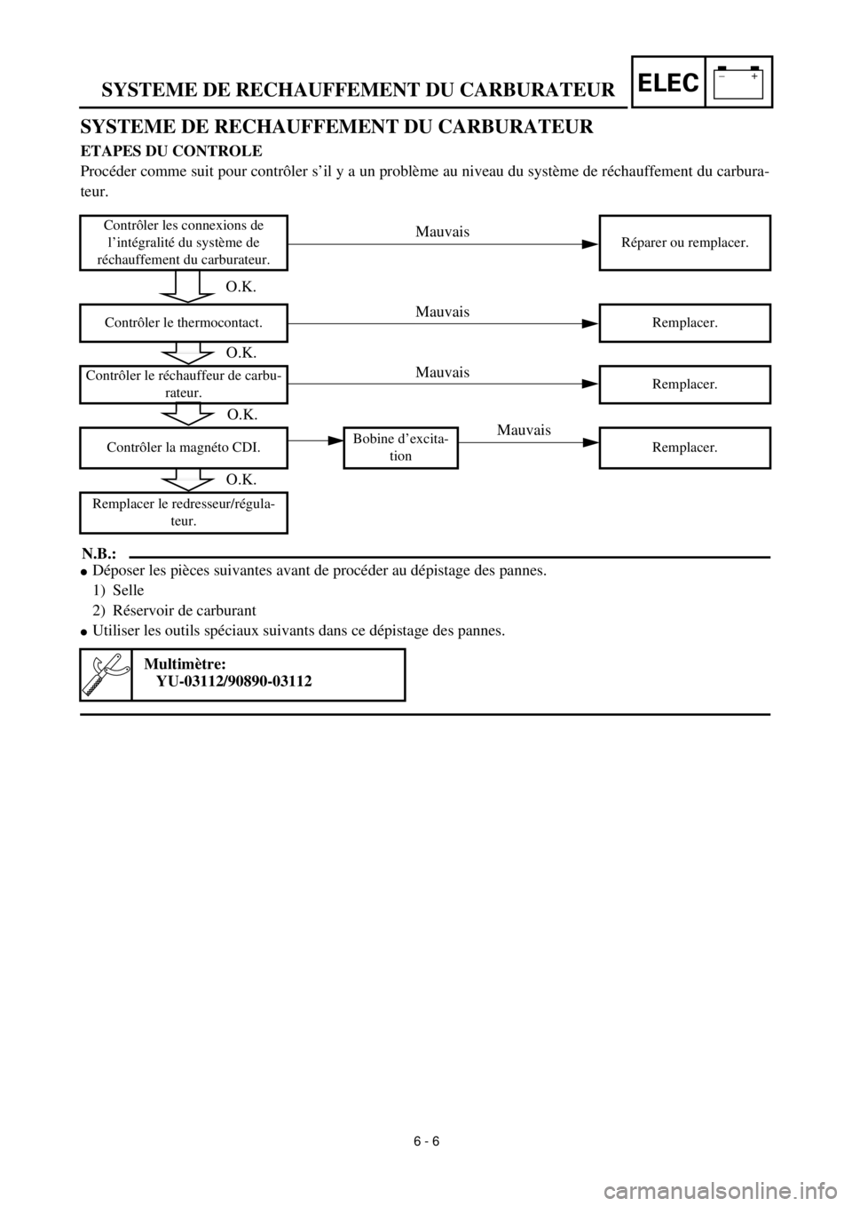
SYSTEME DE RECHAUFFEMENT DU CARBURATEUR
ETAPES DU CONTROLE
Procéder comme suit pour contrôler s’il y a un problème au niveau du système de réchauffement du carbura-
teur.
N.B.:
lDéposer les pièces suivantes avant de procéder au dépistage des pannes.
1) Selle
2) Réservoir de carburant
lUtiliser les outils spéciaux suivants dans ce dépistage des pannes.
Contrôler les connexions de
l’intégralité du système de
réchauffement du carburateur.Réparer ou remplacer.
Contrôler le thermocontact. Remplacer.
Contrôler le réchauffeur de carbu-
rateur.Remplacer.
Contrôler la magnéto CDI.Bobine d’excita-
tionRemplacer.
Remplacer le redresseur/régula-
teur.
Multimètre:
YU-03112/90890-03112
6 - 6
Mauvais
Mauvais
Mauvais
Mauvais
O.K.
O.K.
O.K.
O.K.
Page 278 of 287
–+ELECVERGASERBEHEIZUNGSSYSTEM
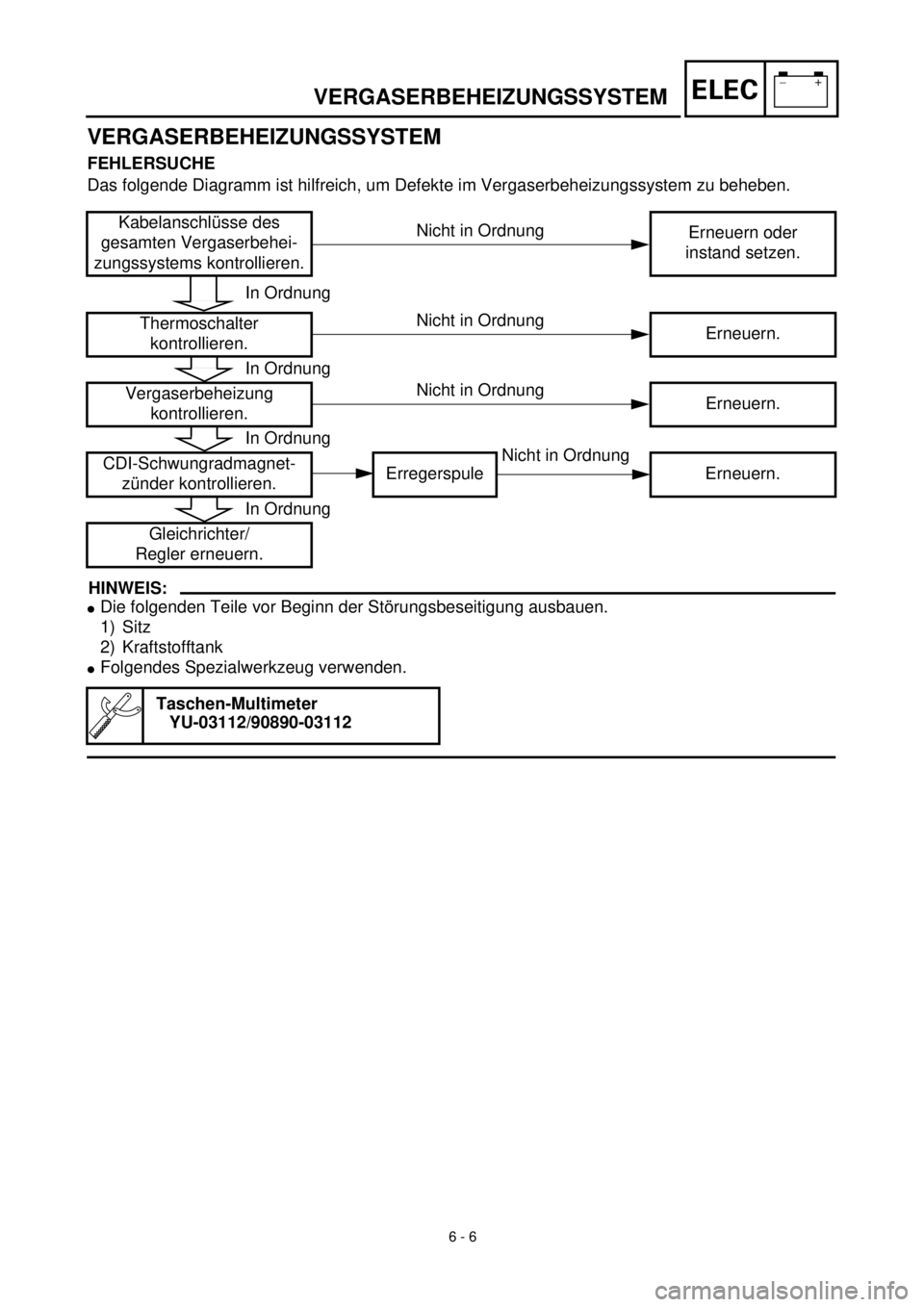
VERGASERBEHEIZUNGSSYSTEM
FEHLERSUCHE
Das folgende Diagramm ist hilfreich, um Defekte im Vergaserbeheizungssystem zu beheben.
HINWEIS:
lDie folgenden Teile vor Beginn der Störungsbeseitigung ausbauen.
1) Sitz
2) Kraftstofftank
lFolgendes Spezialwerkzeug verwenden.
Kabelanschlüsse des
gesamten Vergaserbehei-
zungssystems kontrollieren.Erneuern oder
instand setzen.
Thermoschalter
kontrollieren.Erneuern.
Vergaserbeheizung
kontrollieren.Erneuern.
CDI-Schwungradmagnet-
zünder kontrollieren.Erregerspule Erneuern.
Gleichrichter/
Regler erneuern.
Taschen-Multimeter
YU-03112/90890-03112
6 - 6
Nicht in Ordnung
Nicht in Ordnung
Nicht in Ordnung
Nicht in Ordnung
In Ordnung
In Ordnung
In Ordnung
In Ordnung
Page 279 of 287

–+ELEC
MEMO
Page 280 of 287
6 - 7
–+ELECCARBURETOR HEATING SYSTEM
EC624000
COUPLERS AND LEADS CONNECTION
INSPECTION
1. Check:
lCouplers and leads connection
Rust/dust/looseness/short-circuit ®
Repair or replace.
CDI MAGNETO INSPECTION
1. Inspect:
lSource coil resistance
Refer to “IGNITION SYSTEM” section.
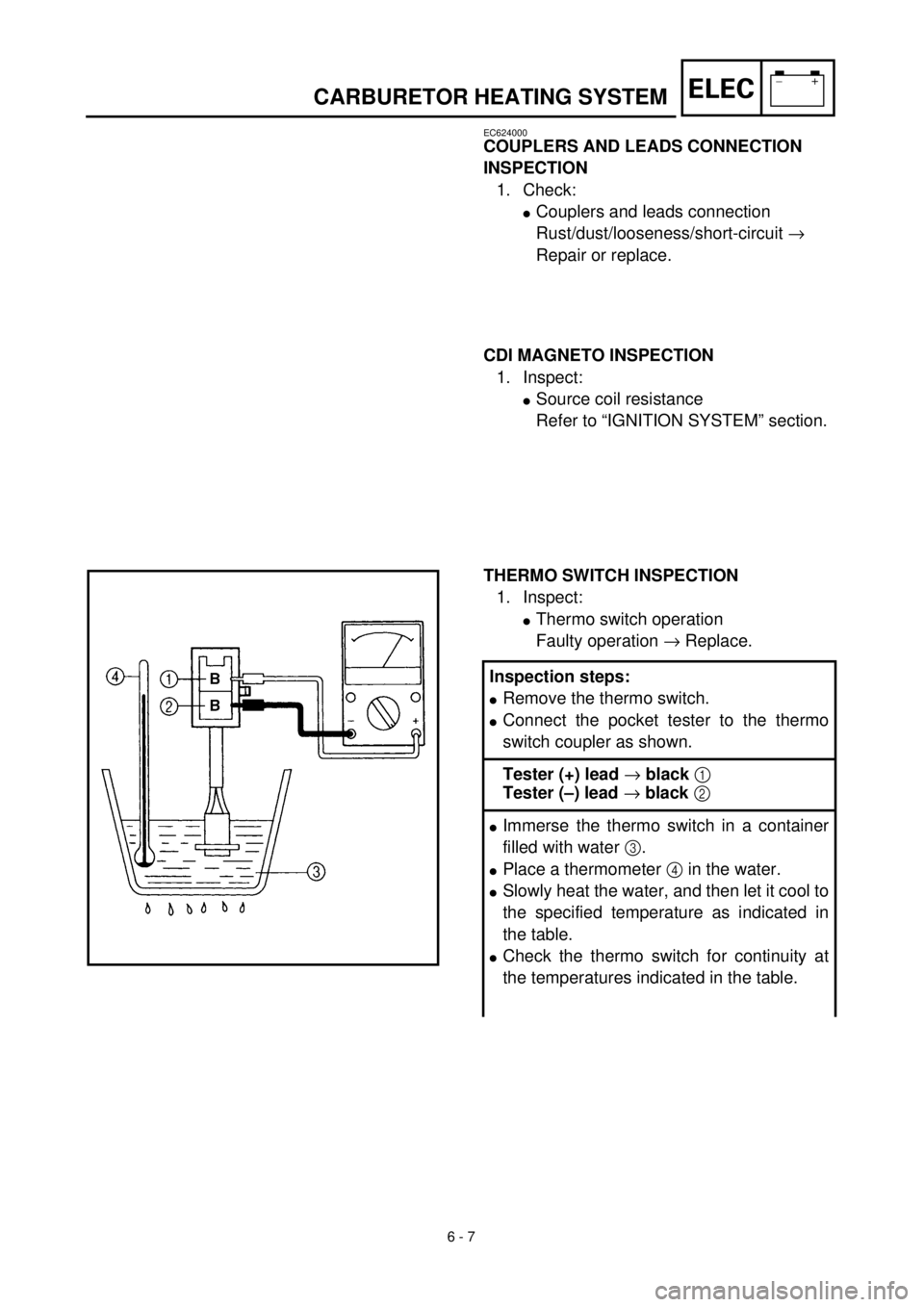
THERMO SWITCH INSPECTION
1. Inspect:
lThermo switch operation
Faulty operation ® Replace.
Inspection steps:
lRemove the thermo switch.
lConnect the pocket tester to the thermo
switch coupler as shown.
Tester (+) lead ® black 1
Tester (–) lead ® black 2
lImmerse the thermo switch in a container
filled with water 3.
lPlace a thermometer 4 in the water.
lSlowly heat the water, and then let it cool to
the specified temperature as indicated in
the table.
lCheck the thermo switch for continuity at
the temperatures indicated in the table.