length YAMAHA TTR90 2006 Notices Demploi (in French)
[x] Cancel search | Manufacturer: YAMAHA, Model Year: 2006, Model line: TTR90, Model: YAMAHA TTR90 2006Pages: 390, PDF Size: 9.12 MB
Page 8 of 390
4. When transporting the machine in
another vehicle, be sure is kept
upright and that the fuel cock is
turned to the “OFF”. If it should lean
over, gasoline may leak out of the car-
buretor or fuel tank.
5. Never start your engine or let it run
for any length of time in a closed
area. The exhaust fumes are poison-
ous and may cause loss of con-
sciousness and death within a short
time. Always operate your machine in
an area with adequate ventilation.
6. Always wear a helmet, gloves, boots,
trousers, and jacket for motocross
riding.
Page 54 of 390
GEN
INFO
1 - 13
STARTING AND OPERATION
STARTING AND OPERATION
CAUTION:
Prior to operating the machine, perform
steps listed in pre-operation check list.
WARNING
Never start your engine or let it run for any
length of time in a closed area. The exhaust
fumes are poisonous and can cause loss of
consciousness and death within a short
time. Always operate your machine in an
area with adequate ventilation.
STARTING A COLD ENGINE
TT-R90
WARNING
Before starting the engine, be sure to shift
the transmission into neutral.
1. Turn the fuel cock to “ON”.
2. Operate the starter (choke) and completely
close the throttle grip.
3. Slide the “ENGINE STOP” switch to the
“”.
4. Kick the kick starter with full strength to
start the engine.
5. After the engine starts, warm up for one or
two minutes. Make sure the stater (choke)
is returned to the original position before
riding.
TT-R90E
WARNING
Before starting the engine, be sure to shift
the transmission into neutral.
NOTE:
This model is equipped with an ignition cir-
cuit cut-off system. In case of electric start-
ing, the engine can be started only when the
transmission is in neutral.
If the engine fails to start by pushing the start
switch, release the switch, wait a few sec-
onds, and then try again. Each starting
attempt should be as short as possible to
preserve the battery. Do not crank the
engine more than 10 seconds on any one
attempt. If the engine does not start with the
starter motor, try using the kickstarter.1. Turn the fuel cock to “ON”.
2. Turn the main switch to “ON”.
3. Shift the transmission into neutral.
4. Operate the starter (choke) and completely
close the throttle grip.
5. Slide the “ENGINE STOP” switch to the
“”.
6. Start the engine by pushing the start switch
or by kicking the kickstarter.
7. After the engine starts, warm up for one or
two minutes. Make sure the stater (choke) is
returned to the original position before riding.
STARTING A WARM ENGINE
To start a warm engine, refer to the “Starting a
cold engine” section. The starter (choke)
should not be used. The throttle should be
opened slightly.
CAUTION:
See “Engine break-in Section” prior to
operating engine for the first time.
WARMING UP
To get maximum engine life, always “warm-up”
the engine before starting off. Never accelerate
hard with a cold engine! To see whether or not
the engine is warm, see if it responds to throttle
normally with the stater (choke) turned off.
WARNING
Before starting off, be sure to turn up or
remove the side stand.
Failure to retract the side stand completely
can result in a serious accident when you
try to turn a corner.
ENGINE BREAK-IN
Brake-in is important to better fit the moving
and sliding parts as well as the installed parts.
It is also important to accustom the rider to the
machine better.
Avoid full-throttle run on a new machine for the
first 5 hours.
After the trial run, check for loose parts, oil
leakage and other problems.
Make full inspection and adjustment especially of
slack cables and drive chain and loose spokes.
CAUTION:
After the break-in period, check every fit-
ting and fastener for looseness.
If any loose is found, retighten it securely.
Page 60 of 390
SPEC
2 - 1
EC200000
SPECIFICATIONS
EC211000
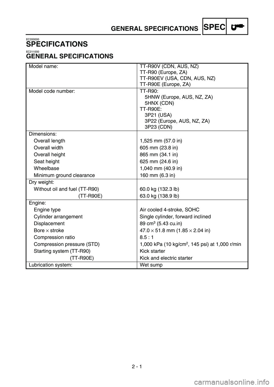
GENERAL SPECIFICATIONS
Model name: TT-R90V (CDN, AUS, NZ)
TT-R90 (Europe, ZA)
TT-R90EV (USA, CDN, AUS, NZ)
TT-R90E (Europe, ZA)
Model code number: TT-R90:
5HNW (Europe, AUS, NZ, ZA)
5HNX (CDN)
TT-R90E:
3P21 (USA)
3P22 (Europe, AUS, NZ, ZA)
3P23 (CDN)
Dimensions:
Overall length 1,525 mm (57.0 in)
Overall width 605 mm (23.8 in)
Overall height 865 mm (34.1 in)
Seat height 625 mm (24.6 in)
Wheelbase 1,040 mm (40.9 in)
Minimum ground clearance 160 mm (6.3 in)
Dry weight:
Without oil and fuel (TT-R90) 60.0 kg (132.3 lb)
(TT-R90E) 63.0 kg (138.9 lb)
Engine:
Engine type Air cooled 4-stroke, SOHC
Cylinder arrangement Single cylinder, forward inclined
Displacement 89 cm
3 (5.43 cu.in)
Bore × stroke 47.0 × 51.8 mm (1.85 × 2.04 in)
Compression ratio 8.5 : 1
Compression pressure (STD) 1,000 kPa (10 kg/cm
2, 145 psi) at 1,000 r/min
Starting system (TT-R90) Kick starter
(TT-R90E) Kick and electric starter
Lubrication system: Wet sump
GENERAL SPECIFICATIONS
Page 65 of 390
SPEC
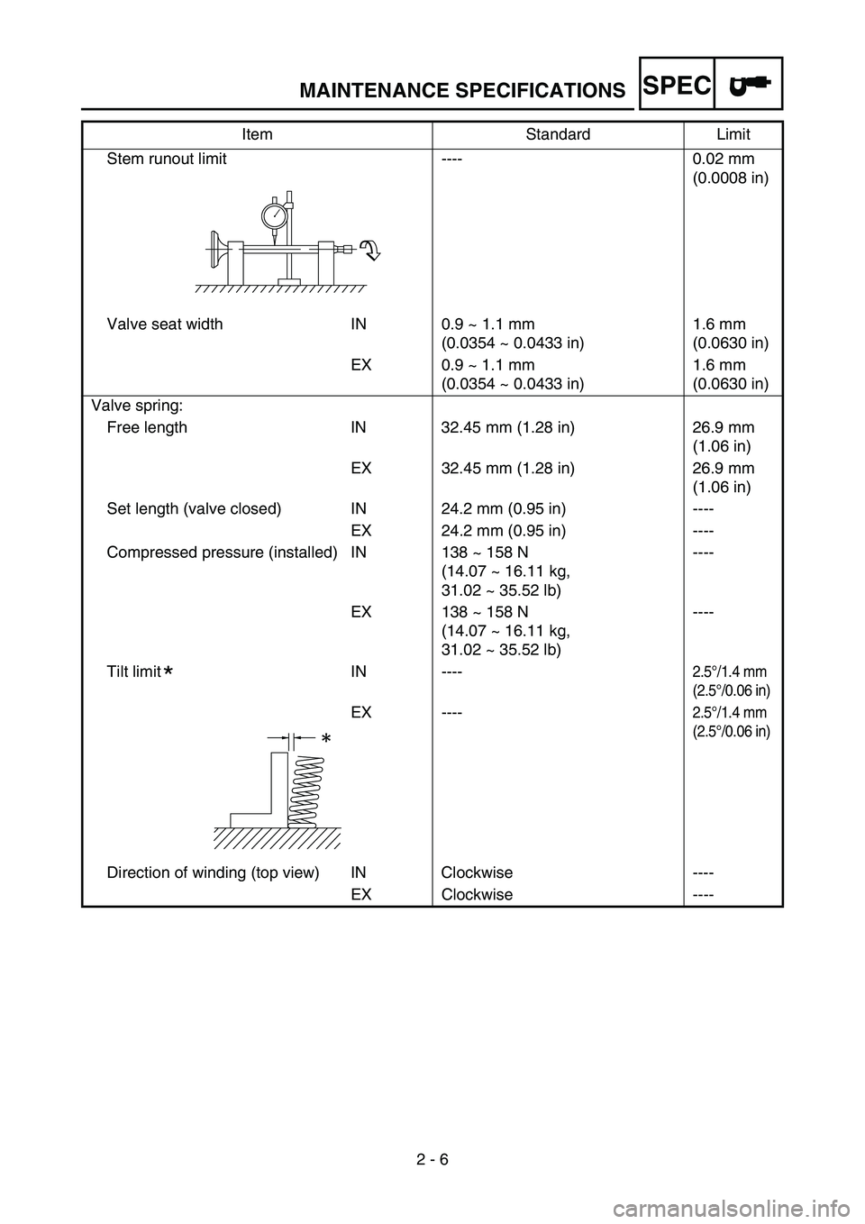
2 - 6 Stem runout limit ---- 0.02 mm
(0.0008 in)
Valve seat width IN 0.9 ~ 1.1 mm
(0.0354 ~ 0.0433 in)1.6 mm
(0.0630 in)
EX 0.9 ~ 1.1 mm
(0.0354 ~ 0.0433 in)1.6 mm
(0.0630 in)
Valve spring:
Free length IN 32.45 mm (1.28 in) 26.9 mm
(1.06 in)
EX 32.45 mm (1.28 in) 26.9 mm
(1.06 in)
Set length (valve closed) IN 24.2 mm (0.95 in) ----
EX 24.2 mm (0.95 in) ----
Compressed pressure (installed) IN 138 ~ 158 N
(14.07 ~ 16.11 kg,
31.02 ~ 35.52 lb)----
EX 138 ~ 158 N
(14.07 ~ 16.11 kg,
31.02 ~ 35.52 lb)----
Tilt limit IN ----
2.5°/1.4 mm
(2.5°/0.06 in)
EX ----2.5°/1.4 mm
(2.5°/0.06 in)
Direction of winding (top view) IN Clockwise ----
EX Clockwise ---- Item Standard Limit
*
MAINTENANCE SPECIFICATIONS
Page 67 of 390
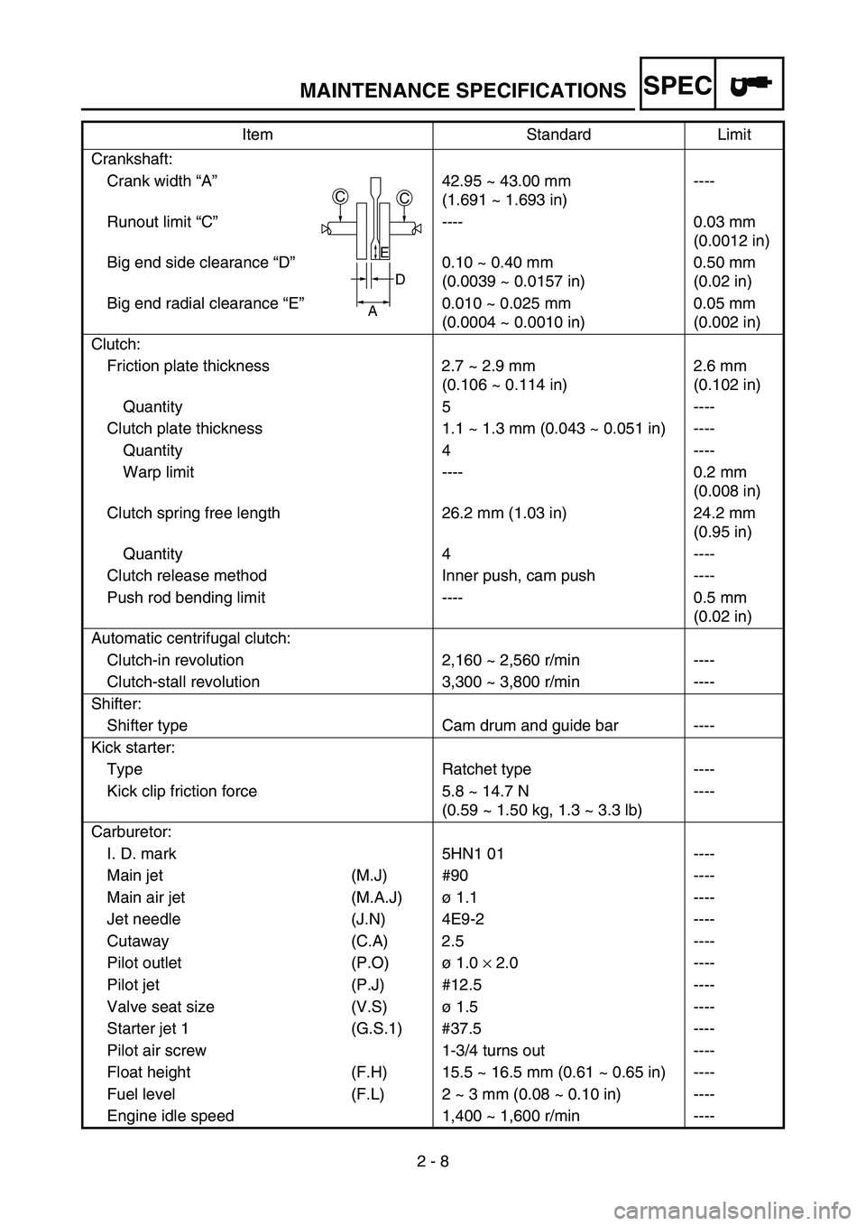
SPEC
2 - 8 Crankshaft:
Crank width “A”42.95 ~ 43.00 mm
(1.691 ~ 1.693 in)----
Runout limit “C”---- 0.03 mm
(0.0012 in)
Big end side clearance “D”0.10 ~ 0.40 mm
(0.0039 ~ 0.0157 in)0.50 mm
(0.02 in)
Big end radial clearance “E”0.010 ~ 0.025 mm
(0.0004 ~ 0.0010 in)0.05 mm
(0.002 in)
Clutch:
Friction plate thickness 2.7 ~ 2.9 mm
(0.106 ~ 0.114 in)2.6 mm
(0.102 in)
Quantity 5 ----
Clutch plate thickness 1.1 ~ 1.3 mm (0.043 ~ 0.051 in) ----
Quantity 4 ----
Warp limit ---- 0.2 mm
(0.008 in)
Clutch spring free length 26.2 mm (1.03 in) 24.2 mm
(0.95 in)
Quantity 4 ----
Clutch release method Inner push, cam push ----
Push rod bending limit ---- 0.5 mm
(0.02 in)
Automatic centrifugal clutch:
Clutch-in revolution 2,160 ~ 2,560 r/min ----
Clutch-stall revolution 3,300 ~ 3,800 r/min ----
Shifter:
Shifter type Cam drum and guide bar ----
Kick starter:
Type Ratchet type ----
Kick clip friction force 5.8 ~ 14.7 N
(0.59 ~ 1.50 kg, 1.3 ~ 3.3 lb)----
Carburetor:
I. D. mark 5HN1 01 ----
Main jet (M.J) #90 ----
Main air jet (M.A.J)ø 1.1 ----
Jet needle (J.N) 4E9-2 ----
Cutaway (C.A) 2.5 ----
Pilot outlet (P.O)ø 1.0 × 2.0 ----
Pilot jet (P.J) #12.5 ----
Valve seat size (V.S)ø 1.5 ----
Starter jet 1 (G.S.1) #37.5 ----
Pilot air screw 1-3/4 turns out ----
Float height (F.H) 15.5 ~ 16.5 mm (0.61 ~ 0.65 in) ----
Fuel level (F.L) 2 ~ 3 mm (0.08 ~ 0.10 in) ----
Engine idle speed 1,400 ~ 1,600 r/min ----Item Standard Limit
CC
D
A
E
MAINTENANCE SPECIFICATIONS
Page 70 of 390
SPEC
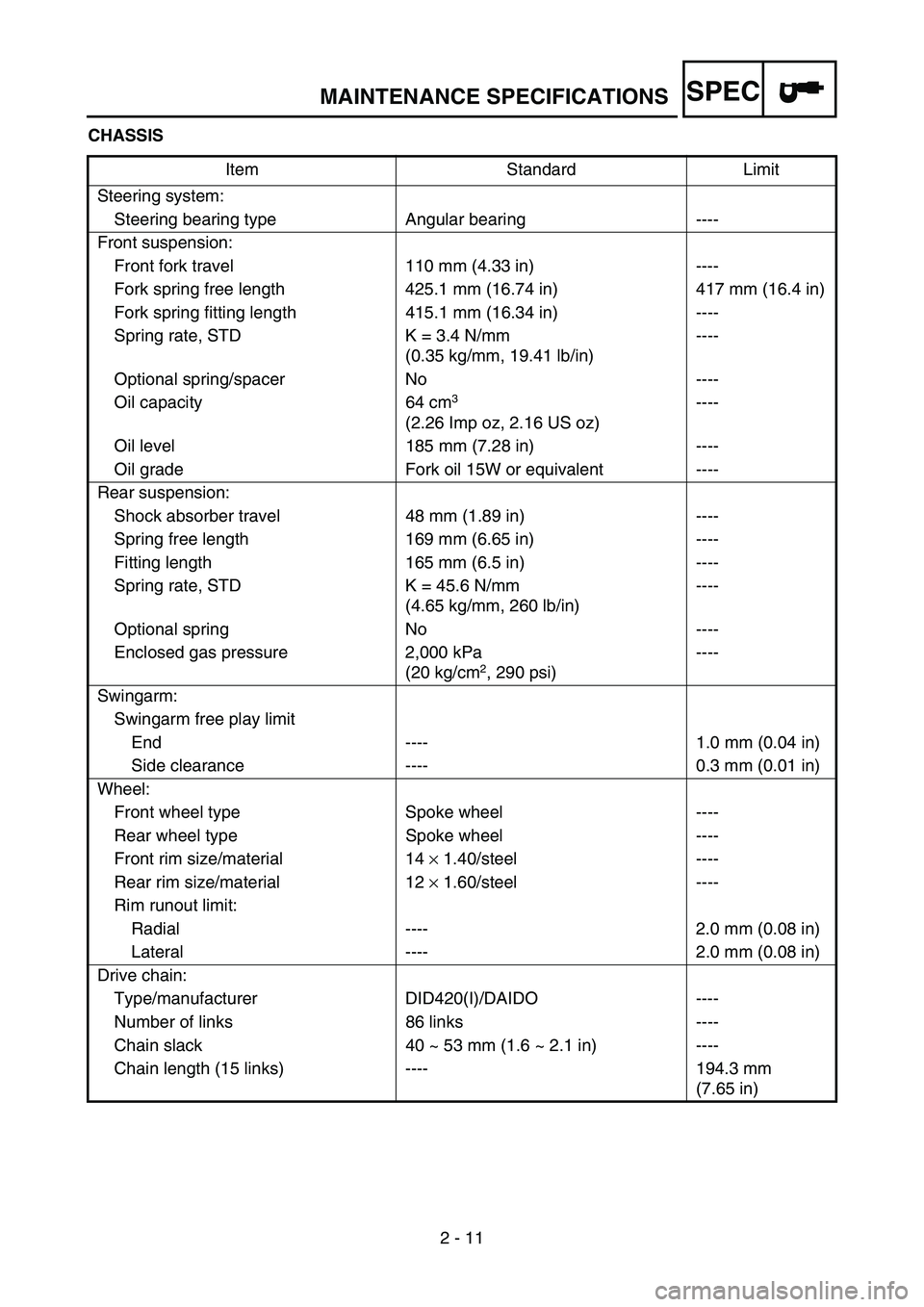
2 - 11 CHASSIS
Item Standard Limit
Steering system:
Steering bearing type Angular bearing ----
Front suspension:
Front fork travel 110 mm (4.33 in) ----
Fork spring free length 425.1 mm (16.74 in) 417 mm (16.4 in)
Fork spring fitting length 415.1 mm (16.34 in) ----
Spring rate, STD K = 3.4 N/mm
(0.35 kg/mm, 19.41 lb/in)----
Optional spring/spacer No ----
Oil capacity 64 cm
3
(2.26 Imp oz, 2.16 US oz) ----
Oil level 185 mm (7.28 in) ----
Oil grade Fork oil 15W or equivalent ----
Rear suspension:
Shock absorber travel 48 mm (1.89 in) ----
Spring free length 169 mm (6.65 in) ----
Fitting length 165 mm (6.5 in) ----
Spring rate, STD K = 45.6 N/mm
(4.65 kg/mm, 260 lb/in)----
Optional spring No ----
Enclosed gas pressure 2,000 kPa
(20 kg/cm
2, 290 psi)----
Swingarm:
Swingarm free play limit
End ---- 1.0 mm (0.04 in)
Side clearance ---- 0.3 mm (0.01 in)
Wheel:
Front wheel type Spoke wheel ----
Rear wheel type Spoke wheel ----
Front rim size/material 14 × 1.40/steel ----
Rear rim size/material 12 × 1.60/steel ----
Rim runout limit:
Radial ---- 2.0 mm (0.08 in)
Lateral ---- 2.0 mm (0.08 in)
Drive chain:
Type/manufacturer DID420(I)/DAIDO ----
Number of links 86 links ----
Chain slack 40 ~ 53 mm (1.6 ~ 2.1 in) ----
Chain length (15 links) ---- 194.3 mm
(7.65 in)
MAINTENANCE SPECIFICATIONS
Page 71 of 390
SPEC
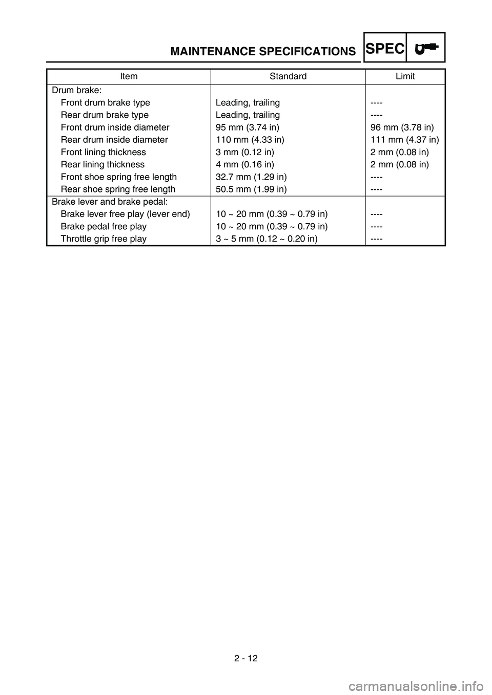
2 - 12 Drum brake:
Front drum brake type Leading, trailing ----
Rear drum brake type Leading, trailing ----
Front drum inside diameter 95 mm (3.74 in) 96 mm (3.78 in)
Rear drum inside diameter 110 mm (4.33 in) 111 mm (4.37 in)
Front lining thickness 3 mm (0.12 in) 2 mm (0.08 in)
Rear lining thickness 4 mm (0.16 in) 2 mm (0.08 in)
Front shoe spring free length 32.7 mm (1.29 in) ----
Rear shoe spring free length 50.5 mm (1.99 in) ----
Brake lever and brake pedal:
Brake lever free play (lever end) 10 ~ 20 mm (0.39 ~ 0.79 in) ----
Brake pedal free play 10 ~ 20 mm (0.39 ~ 0.79 in) ----
Throttle grip free play 3 ~ 5 mm (0.12 ~ 0.20 in) ----Item Standard Limit
MAINTENANCE SPECIFICATIONS
Page 74 of 390
SPEC
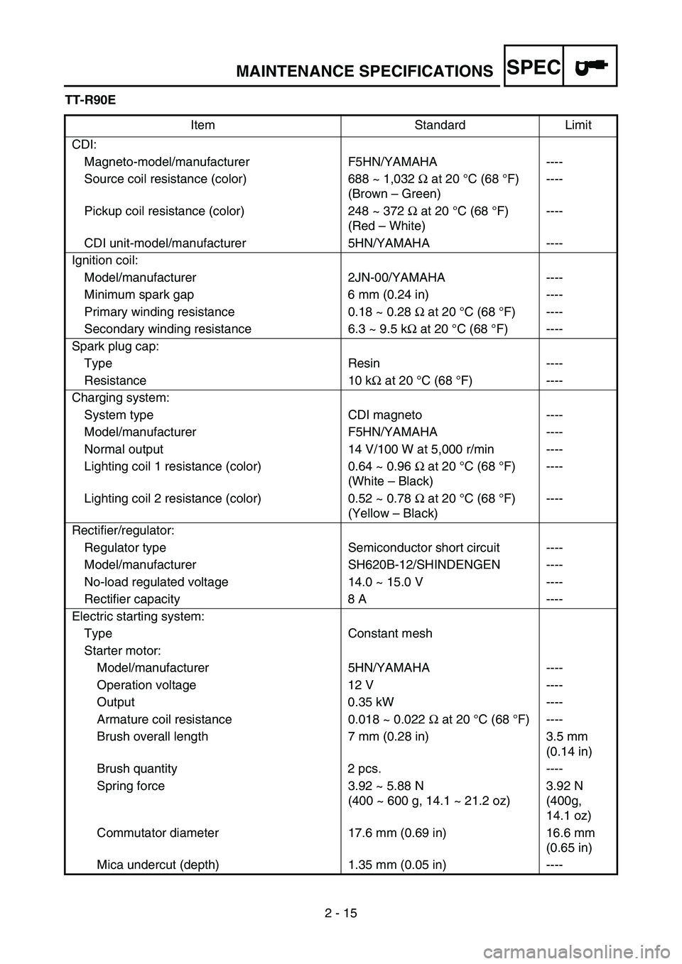
2 - 15 TT-R90E
Item Standard Limit
CDI:
Magneto-model/manufacturer F5HN/YAMAHA ----
Source coil resistance (color) 688 ~ 1,032 Ω at 20 °C (68 °F)
(Brown – Green)----
Pickup coil resistance (color) 248 ~ 372 Ω at 20 °C (68 °F)
(Red – White)----
CDI unit-model/manufacturer 5HN/YAMAHA ----
Ignition coil:
Model/manufacturer 2JN-00/YAMAHA ----
Minimum spark gap 6 mm (0.24 in) ----
Primary winding resistance 0.18 ~ 0.28 Ω at 20 °C (68 °F) ----
Secondary winding resistance 6.3 ~ 9.5 kΩ at 20 °C (68 °F) ----
Spark plug cap:
Type Resin ----
Resistance 10 kΩ at 20 °C (68 °F) ----
Charging system:
System type CDI magneto ----
Model/manufacturer F5HN/YAMAHA ----
Normal output 14 V/100 W at 5,000 r/min ----
Lighting coil 1 resistance (color) 0.64 ~ 0.96 Ω at 20 °C (68 °F)
(White – Black)----
Lighting coil 2 resistance (color) 0.52 ~ 0.78 Ω at 20 °C (68 °F)
(Yellow – Black)----
Rectifier/regulator:
Regulator type Semiconductor short circuit ----
Model/manufacturer SH620B-12/SHINDENGEN ----
No-load regulated voltage 14.0 ~ 15.0 V ----
Rectifier capacity 8 A ----
Electric starting system:
Type Constant mesh
Starter motor:
Model/manufacturer 5HN/YAMAHA ----
Operation voltage 12 V ----
Output 0.35 kW ----
Armature coil resistance 0.018 ~ 0.022 Ω at 20 °C (68 °F) ----
Brush overall length 7 mm (0.28 in) 3.5 mm
(0.14 in)
Brush quantity 2 pcs. ----
Spring force 3.92 ~ 5.88 N
(400 ~ 600 g, 14.1 ~ 21.2 oz)3.92 N
(400g,
14.1 oz)
Commutator diameter 17.6 mm (0.69 in) 16.6 mm
(0.65 in)
Mica undercut (depth) 1.35 mm (0.05 in) ----
MAINTENANCE SPECIFICATIONS
Page 76 of 390
SPEC
2 - 17
EC220001
GENERAL TORQUE SPECIFICATIONS
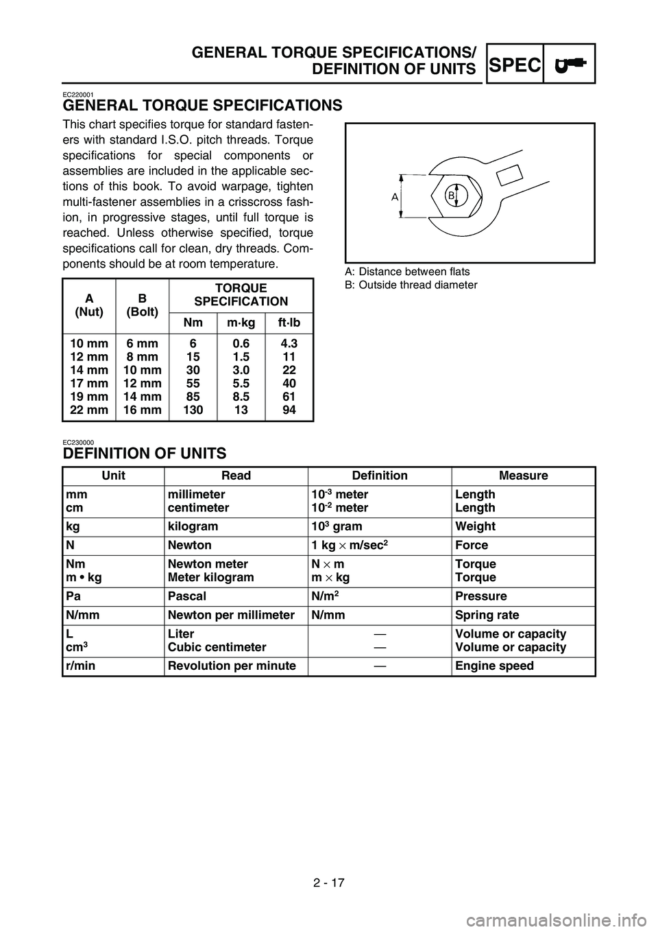
This chart specifies torque for standard fasten-
ers with standard I.S.O. pitch threads. Torque
specifications for special components or
assemblies are included in the applicable sec-
tions of this book. To avoid warpage, tighten
multi-fastener assemblies in a crisscross fash-
ion, in progressive stages, until full torque is
reached. Unless otherwise specified, torque
specifications call for clean, dry threads. Com-
ponents should be at room temperature.
A: Distance between flats
B: Outside thread diameter
EC230000
DEFINITION OF UNITS
A
(Nut)B
(Bolt)TORQUE
SPECIFICATION
Nm m·kg ft·lb
10 mm
12 mm
14 mm
17 mm
19 mm
22 mm6 mm
8 mm
10 mm
12 mm
14 mm
16 mm6
15
30
55
85
1300.6
1.5
3.0
5.5
8.5
134.3
11
22
40
61
94
Unit Read Definition Measure
mm
cmmillimeter
centimeter10
-3 meter
10-2 meterLength
Length
kg kilogram 10
3 gram Weight
N Newton 1 kg
× m/sec
2 Force
Nm
m kgNewton meter
Meter kilogramN
× m
m
× kgTorque
Torque
Pa Pascal N/m
2Pressure
N/mm Newton per millimeter N/mm Spring rate
L
cm
3 Liter
Cubic centimeter—
—Volume or capacity
Volume or capacity
r/min Revolution per minute
—Engine speed
GENERAL TORQUE SPECIFICATIONS/
DEFINITION OF UNITS
Page 156 of 390
3 - 13
INSP
ADJ
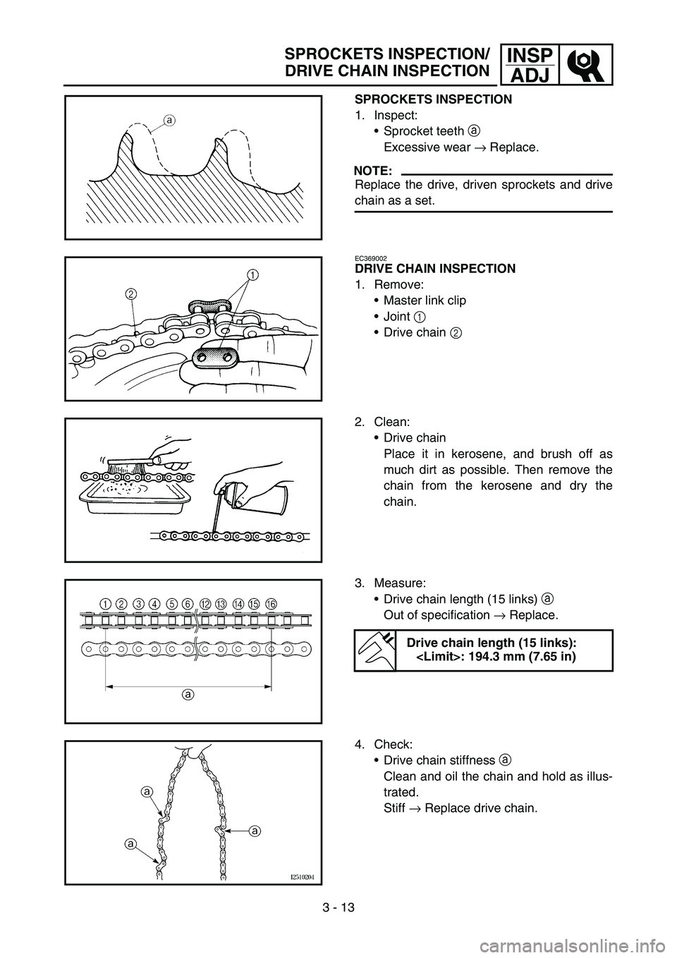
SPROCKETS INSPECTION
1. Inspect:
Sprocket teeth a
Excessive wear → Replace.
NOTE:
Replace the drive, driven sprockets and drive
chain as a set.
EC369002
DRIVE CHAIN INSPECTION
1. Remove:
Master link clip
Joint 1
Drive chain 2
2. Clean:
Drive chain
Place it in kerosene, and brush off as
much dirt as possible. Then remove the
chain from the kerosene and dry the
chain.
3. Measure:
Drive chain length (15 links) a
Out of specification → Replace.
Drive chain length (15 links):
4. Check:
Drive chain stiffness a
Clean and oil the chain and hold as illus-
trated.
Stiff → Replace drive chain.
SPROCKETS INSPECTION/
DRIVE CHAIN INSPECTION