YAMAHA TTR90 2006 Owners Manual
Manufacturer: YAMAHA, Model Year: 2006, Model line: TTR90, Model: YAMAHA TTR90 2006Pages: 390, PDF Size: 9.12 MB
Page 331 of 390
5 - 18
CHAS
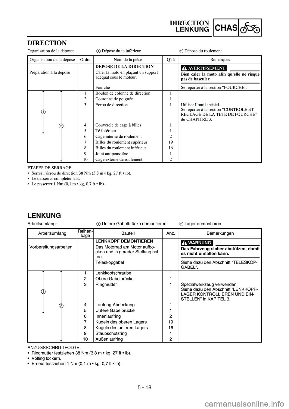
DIRECTION
Organisation de la dépose:1 Dépose du té inférieur2 Dépose du roulement
ETAPES DE SERRAGE:
Serrer l’écrou de direction 38 Nm (3,8 m kg, 27 ft lb).
Le desserrer complètement.
Le resserrer 1 Nm (0,1 m kg, 0,7 ft lb). Organisation de la dépose Ordre Nom de la pièce Q’téRemarques
DEPOSE DE LA DIRECTION
AVERTISSEMENT
Bien caler la moto afin qu’elle ne risque
pas de basculer. Préparation à la dépose Caler la moto en plaçant un support
adéquat sous le moteur.
Fourche Se reporter à la section “FOURCHE”.
1 Boulon de colonne de direction 1
2 Couronne de poignée1
3 Ecrou de direction 1 Utiliser l’outil spécial.
Se reporter à la section “CONTROLE ET
REGLAGE DE LA TETE DE FOURCHE”
du CHAPITRE 3.
4 Couvercle de cage à billes 1
5Té inférieur 1
6 Cage interne de roulement 2
7 Billes du roulement supérieur 19
8 Billes du roulement inférieur 16
9 Joint antipoussière 1
10 Cage externe de roulement 2
2
1
LENKUNG
Arbeitsumfang:
1 Untere Gabelbrücke demontieren
2 Lager demontieren
ANZUGSSCHRITTFOLGE:
Ringmutter festziehen 38 Nm (3,8 m kg, 27 ft lb).
Völling lockern.
Erneut festziehen 1 Nm (0,1 m kg, 0,7 ft lb). ArbeitsumfangReihen-
folgeBauteil Anz. Bemerkungen
LENKKOPF DEMONTIEREN
WARNUNG
Das Fahrzeug sicher abstützen, damit
es nicht umfallen kann. Vorbereitungsarbeiten Das Motorrad am Motor aufbo-
cken und in gerader Stellung hal-
ten.
Teleskopgabel Siehe dazu den Abschnitt “TELESKOP-
GABEL”.
1 Lenkkopfschraube 1
2 Obere Gabelbrücke 1
3 Ringmutter 1 Spezialwerkzeug verwenden.
Siehe dazu den Abschnitt “LENKKOPF-
LAGER KONTROLLIEREN UND EIN-
STELLEN” in KAPITEL 3.
4 Laufring-Abdeckung 1
5 Untere Gabelbrücke 1
6 Innenlaufring 2
7 Kugeln des oberen Lagers 19
8 Kugeln des unteren Lagers 16
9 Staubschutzring 1
10 Außenlaufring 2
2
1
DIRECTION
LENKUNG
Page 332 of 390
5 - 19
CHAS
EC563000
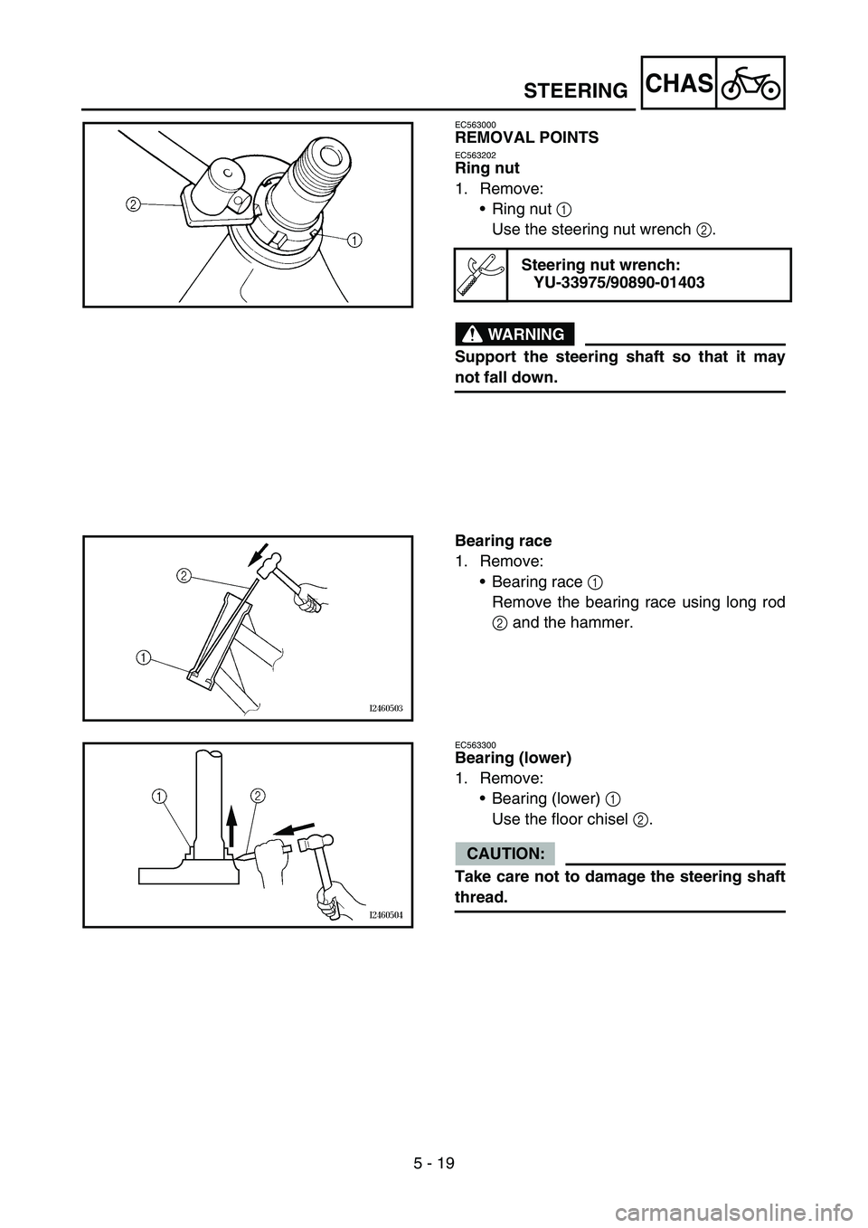
REMOVAL POINTS
EC563202
Ring nut
1. Remove:
Ring nut 1
Use the steering nut wrench 2.
WARNING
Support the steering shaft so that it may
not fall down.
Steering nut wrench:
YU-33975/90890-01403
Bearing race
1. Remove:
Bearing race 1
Remove the bearing race using long rod
2 and the hammer.
EC563300
Bearing (lower)
1. Remove:
Bearing (lower) 1
Use the floor chisel 2.
CAUTION:
Take care not to damage the steering shaft
thread.
STEERING
Page 333 of 390
5 - 19
CHAS
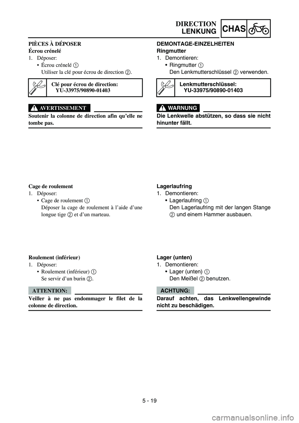
DEMONTAGE-EINZELHEITEN
Ringmutter
1. Demontieren:
Ringmutter 1
Den Lenkmutterschlüssel 2 verwenden.
WARNUNG
Die Lenkwelle abstützen, so dass sie nicht
hinunter fällt.
Lenkmutterschlüssel:
YU-33975/90890-01403
Lagerlaufring
1. Demontieren:
Lagerlaufring 1
Den Lagerlaufring mit der langen Stange
2 und einem Hammer ausbauen.
Lager (unten)
1. Demontieren:
Lager (unten) 1
Den Meißel 2 benutzen.
ACHTUNG:
Darauf achten, das Lenkwellengewinde
nicht zu beschädigen.
DIRECTION
LENKUNG
PIÈCES À DÉPOSER
Écrou crénelé
1. Déposer:
Écrou crénelé 1
Utiliser la clé pour écrou de direction 2.
AVERTISSEMENT
Soutenir la colonne de direction afin qu’elle ne
tombe pas.
Clé pour écrou de direction:
YU-33975/90890-01403
Cage de roulement
1. Déposer:
Cage de roulement 1
Déposer la cage de roulement à l’aide d’une
longue tige 2 et d’un marteau.
Roulement (inférieur)
1. Déposer:
Roulement (inférieur) 1
Se servir d’un burin 2.
ATTENTION:
Veiller à ne pas endommager le filet de la
colonne de direction.
Page 334 of 390
5 - 20
CHASSWINGARM
EC570000
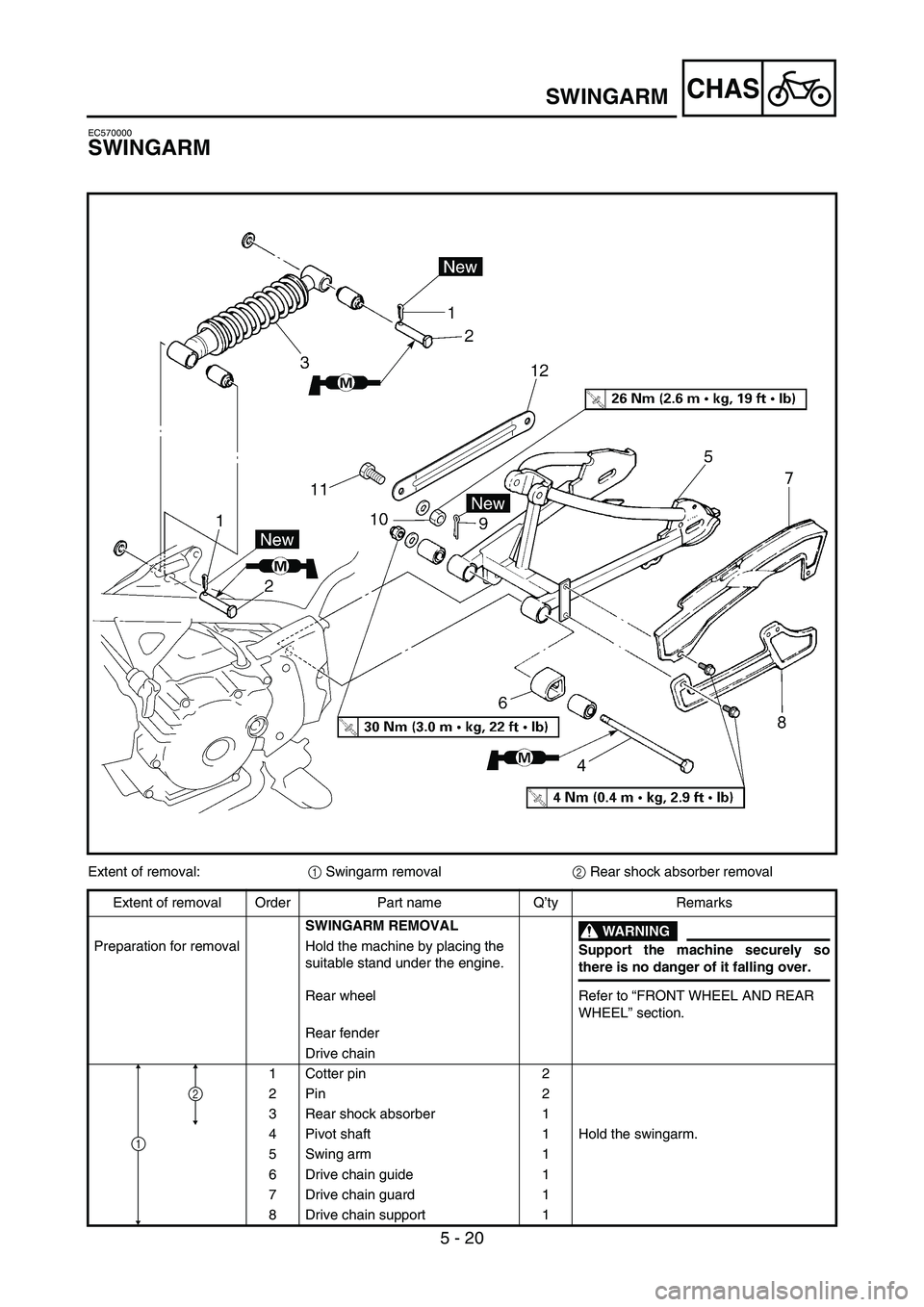
SWINGARM
Extent of removal:
1 Swingarm removal
2 Rear shock absorber removal
Extent of removal Order Part name Q’ty Remarks
SWINGARM REMOVAL
WARNING
Support the machine securely so
there is no danger of it falling over. Preparation for removal Hold the machine by placing the
suitable stand under the engine.
Rear wheel Refer to “FRONT WHEEL AND REAR
WHEEL” section.
Rear fender
Drive chain
1Cotter pin 2
2Pin 2
3 Rear shock absorber 1
4 Pivot shaft 1 Hold the swingarm.
5 Swing arm 1
6 Drive chain guide 1
7 Drive chain guard 1
8 Drive chain support 1
2
1
Page 335 of 390
5 - 20
CHAS
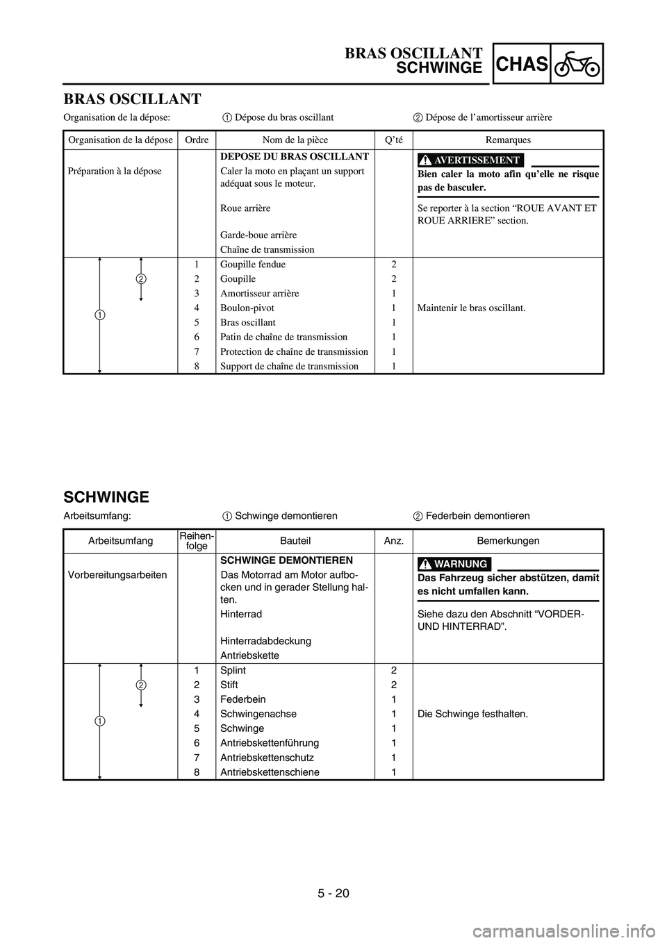
BRAS OSCILLANT
Organisation de la dépose:1 Dépose du bras oscillant2 Dépose de l’amortisseur arrière
Organisation de la dépose Ordre Nom de la pièce Q’téRemarques
DEPOSE DU BRAS OSCILLANT
AVERTISSEMENT
Bien caler la moto afin qu’elle ne risque
pas de basculer. Préparation à la dépose Caler la moto en plaçant un support
adéquat sous le moteur.
Roue arrière Se reporter à la section “ROUE AVANT ET
ROUE ARRIERE” section.
Garde-boue arrière
Chaîne de transmission
1 Goupille fendue 2
2 Goupille 2
3 Amortisseur arrière 1
4 Boulon-pivot 1 Maintenir le bras oscillant.
5 Bras oscillant 1
6 Patin de chaîne de transmission 1
7 Protection de chaîne de transmission 1
8 Support de chaîne de transmission 1
2
1
SCHWINGE
Arbeitsumfang:
1 Schwinge demontieren
2 Federbein demontieren
ArbeitsumfangReihen-
folgeBauteil Anz. Bemerkungen
SCHWINGE DEMONTIEREN
WARNUNG
Das Fahrzeug sicher abstützen, damit
es nicht umfallen kann. Vorbereitungsarbeiten Das Motorrad am Motor aufbo-
cken und in gerader Stellung hal-
ten.
Hinterrad Siehe dazu den Abschnitt “VORDER-
UND HINTERRAD”.
Hinterradabdeckung
Antriebskette
1Splint 2
2 Stift 2
3 Federbein 1
4 Schwingenachse 1 Die Schwinge festhalten.
5 Schwinge 1
6 Antriebskettenführung 1
7 Antriebskettenschutz 1
8 Antriebskettenschiene 1
2
1
BRAS OSCILLANT
SCHWINGE
Page 336 of 390
5 - 21
CHASSWINGARM
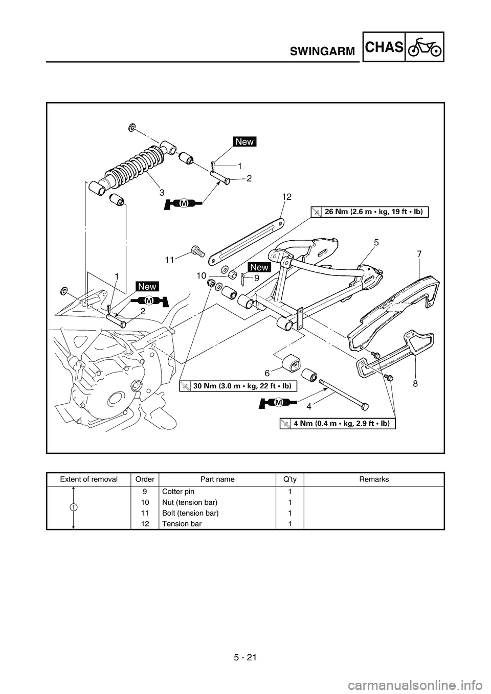
Extent of removal Order Part name Q’ty Remarks
9Cotter pin 1
10 Nut (tension bar) 1
11 Bolt (tension bar) 1
12 Tension bar 1
1
Page 337 of 390
5 - 21
CHAS
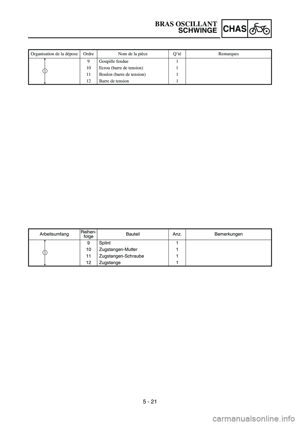
Organisation de la dépose Ordre Nom de la pièce Q’téRemarques
9 Goupille fendue 1
10 Ecrou (barre de tension) 1
11 Boulon (barre de tension) 1
12 Barre de tension 1
1
ArbeitsumfangReihen-
folgeBauteil Anz. Bemerkungen
9Splint 1
10 Zugstangen-Mutter 1
11 Zugstangen-Schraube 1
12 Zugstange 1
1
BRAS OSCILLANT
SCHWINGE
Page 338 of 390
6 - 1
–+ELECELECTRICAL COMPONENTS AND WIRING DIAGRAM
EC600000
ELECTRICAL
EC610000
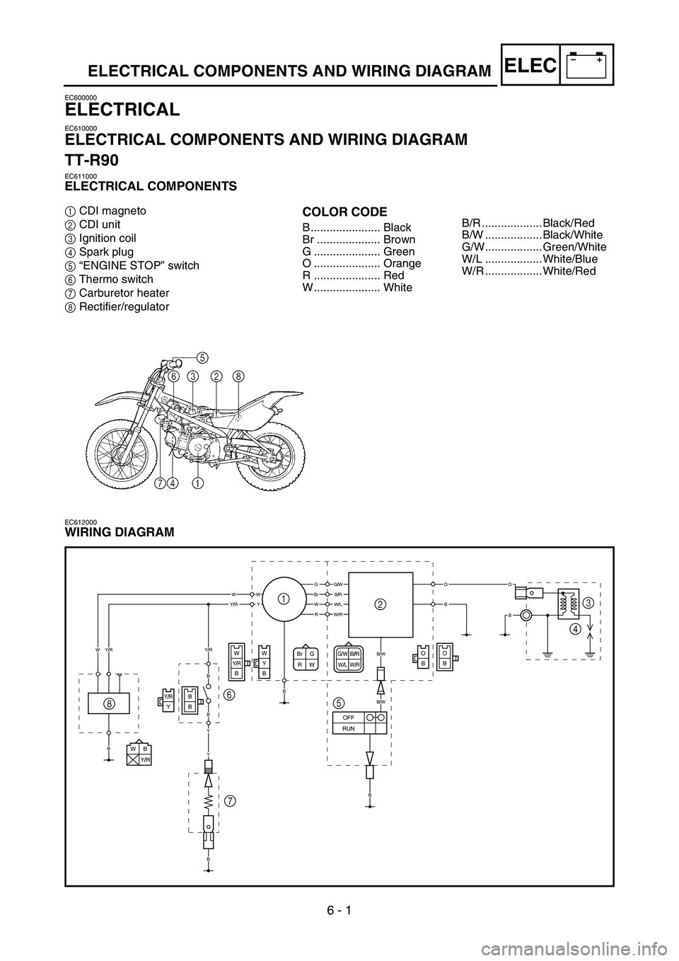
ELECTRICAL COMPONENTS AND WIRING DIAGRAM
TT-R90
EC611000
ELECTRICAL COMPONENTS
1CDI magneto
2CDI unit
3Ignition coil
4Spark plug
5“ENGINE STOP” switch
6Thermo switch
7Carburetor heater
8Rectifier/regulatorCOLOR CODE
B ...................... Black
Br .................... Brown
G ..................... Green
O ..................... Orange
R ..................... Red
W ..................... White
EC612000
WIRING DIAGRAM
G/WB/RW/LW/RBr G
RW
WB
Y/R
O
BO
B
B
BY/RY
WY/RB
W
Y
B
GG/W
B/W
B/W
BrB/RWWWY
OO
BBW/LY/RR
W
B
B
B
W/R
Y/R
OFF
RUN
B
Y/R
B
B
Y
Y
1
23
4
5 6
7 8
B/R ................... Black/Red
B/W .................. Black/White
G/W.................. Green/White
W/L .................. White/Blue
W/R .................. White/Red
Page 339 of 390
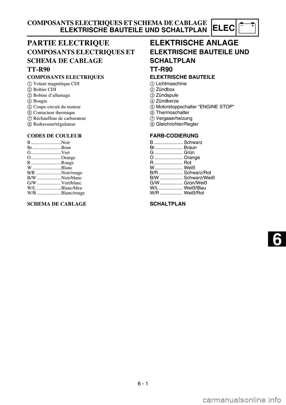
–+ELEC
ELEKTRISCHE ANLAGE
ELEKTRISCHE BAUTEILE UND
SCHALTPLAN
TT-R90
ELEKTRISCHE BAUTEILE
1Lichtmaschine
2Zündbox
3Zündspule
4Zündkerze
5Motorstoppschalter “ENGINE STOP”
6Thermoschalter
7Vergaserheizung
8Gleichrichter/Regler
FARB-CODIERUNG
B ...................... Schwarz
Br ..................... Braun
G ..................... Grün
O ..................... Orange
R ...................... Rot
W ..................... Weiß
B/R .................. Schwarz/Rot
B/W ................. Schwarz/Weiß
G/W ................. Grün/Weiß
W/L .................. Weiß/Blau
W/R ................. Weiß/Rot
SCHALTPLAN
COMPOSANTS ELECTRIQUES ET SCHEMA DE CABLAGE
ELEKTRISCHE BAUTEILE UND SCHALTPLAN
PARTIE ELECTRIQUE
COMPOSANTS ELECTRIQUES ET
SCHEMA DE CABLAGE
TT-R90
COMPOSANTS ELECTRIQUES
1Volant magnétique CDI
2Boîtier CDI
3Bobine d’allumage
4Bougie
5Coupe-circuit du moteur
6Contacteur thermique
7Réchauffeur de carburateur
8Redresseur/régulateur
CODES DE COULEUR
B .........................Noir
Br ........................Brun
G .........................Vert
O .........................Orange
R .........................Rouge
W ........................Blanc
B/R .....................Noir/rouge
B/W ....................Noir/blanc
G/W ....................Vert/blanc
W/L ....................Blanc/bleu
W/R ....................Blanc/rouge
SCHEMA DE CABLAGE
6 - 1
6
Page 340 of 390
6 - 2
–+ELEC
12
3
456
7
0
98
A
B
F
EC
D
ELECTRICAL COMPONENTS AND WIRING DIAGRAM
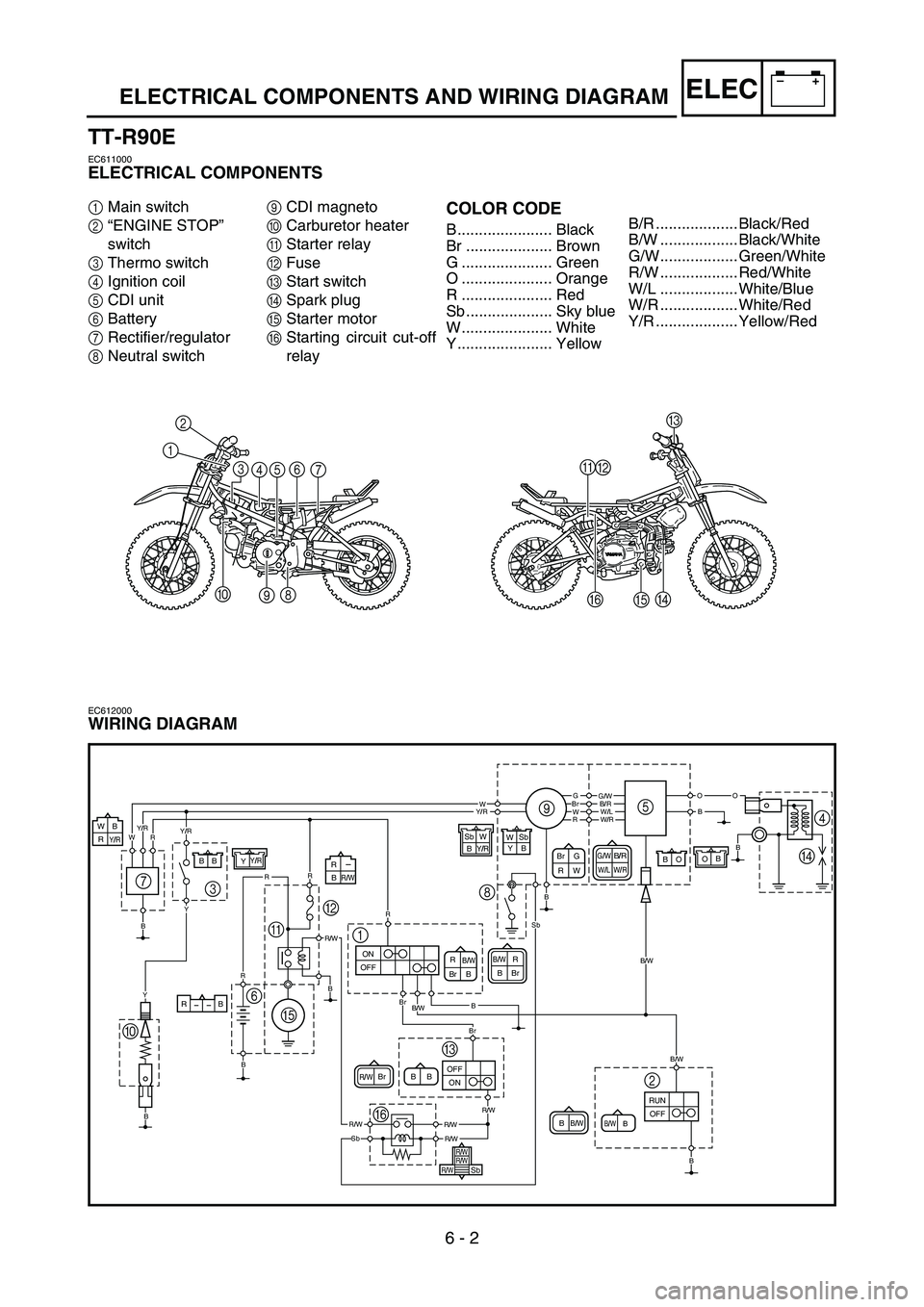
TT-R90E
EC611000
ELECTRICAL COMPONENTS
1Main switch
2“ENGINE STOP”
switch
3Thermo switch
4Ignition coil
5CDI unit
6Battery
7Rectifier/regulator
8Neutral switch9CDI magneto
0Carburetor heater
AStarter relay
BFuse
CStart switch
DSpark plug
EStarter motor
FStarting circuit cut-off
relayCOLOR CODE
B ...................... Black
Br .................... Brown
G ..................... Green
O ..................... Orange
R ..................... Red
Sb .................... Sky blue
W ..................... White
Y ...................... Yellow
EC612000
WIRING DIAGRAM
G/WB/RW/LW/RBr G
RW
B/WBr BRB/WBBrR
B/WB/WBB
BR/WBr B
GG/W
B/W
B/W
BrB/RWWOO
B
BW/LY/RR
W
B
B
R
W/RY/R
OFF RUNB
Y/R
Y
Y
OBO BY/RYB B
Sb
W W
Sb
ON OFF
OFFON
Y
BBY/R
Br
Br
B
B
R
RR
R
B
R/WR/W
R/WR/W
R/W
Sb
Sb
RB
R/WB R
Y/RRB W
B/WB
R/W
R/W
R/W
Sb
9
8
1 B5
4
D
2 3
=A
E 6
C
F 7
B/R ................... Black/Red
B/W .................. Black/White
G/W.................. Green/White
R/W .................. Red/White
W/L .................. White/Blue
W/R .................. White/Red
Y/R ................... Yellow/Red