oil filter YAMAHA TTR90 2006 Owners Manual
[x] Cancel search | Manufacturer: YAMAHA, Model Year: 2006, Model line: TTR90, Model: YAMAHA TTR90 2006Pages: 390, PDF Size: 9.12 MB
Page 61 of 390
SPEC
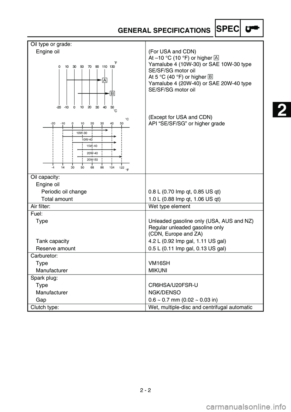
2 - 2 Oil type or grade:
Engine oil
(For USA and CDN)
At –10 °C (10 °F) or higher È
Yamalube 4 (10W-30) or SAE 10W-30 type
SE/SF/SG motor oil
At 5 °C (40 °F) or higher É
Yamalube 4 (20W-40) or SAE 20W-40 type
SE/SF/SG motor oil
(Except for USA and CDN)
API “SE/SF/SG” or higher grade
Oil capacity:
Engine oil
Periodic oil change 0.8 L (0.70 Imp qt, 0.85 US qt)
Total amount 1.0 L (0.88 Imp qt, 1.06 US qt)
Air filter: Wet type element
Fuel:
Type Unleaded gasoline only (USA, AUS and NZ)
Regular unleaded gasoline only
(CDN, Europe and ZA)
Tank capacity 4.2 L (0.92 Imp gal, 1.11 US gal)
Reserve amount 0.5 L (0.11 Imp gal, 0.13 US gal)
Carburetor:
Type VM16SH
Manufacturer MIKUNI
Spark plug:
Type CR6HSA/U20FSR-U
Manufacturer NGK/DENSO
Gap 0.6 ~ 0.7 mm (0.02 ~ 0.03 in)
Clutch type: Wet, multiple-disc and centrifugal automatic
0 10 30 50 70 90 110 130
-20 -10 01020
30 40 50
È
É
˚F
˚C
GENERAL SPECIFICATIONS
1
2
Page 68 of 390
SPEC
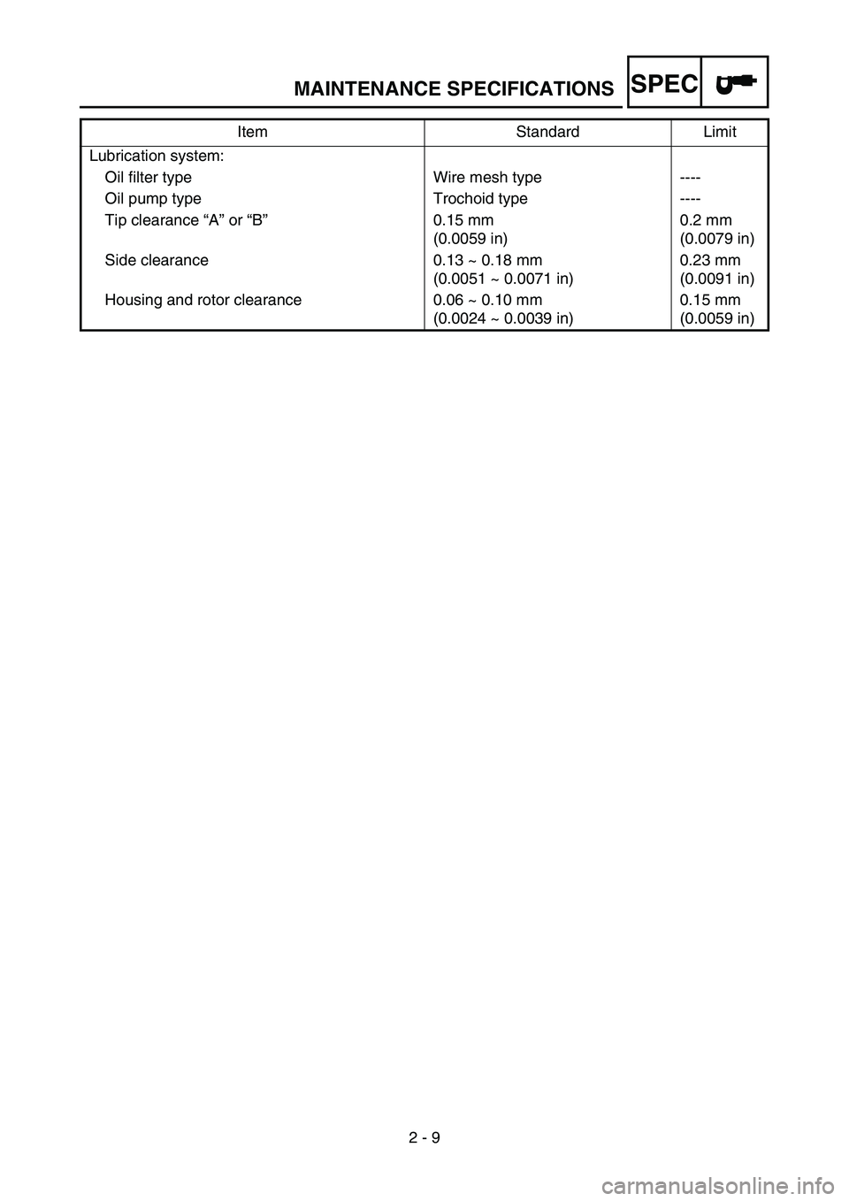
2 - 9 Lubrication system:
Oil filter type Wire mesh type ----
Oil pump type Trochoid type ----
Tip clearance “A” or “B”0.15 mm
(0.0059 in)0.2 mm
(0.0079 in)
Side clearance 0.13 ~ 0.18 mm
(0.0051 ~ 0.0071 in)0.23 mm
(0.0091 in)
Housing and rotor clearance 0.06 ~ 0.10 mm
(0.0024 ~ 0.0039 in)0.15 mm
(0.0059 in) Item Standard Limit
MAINTENANCE SPECIFICATIONS
Page 69 of 390
SPEC
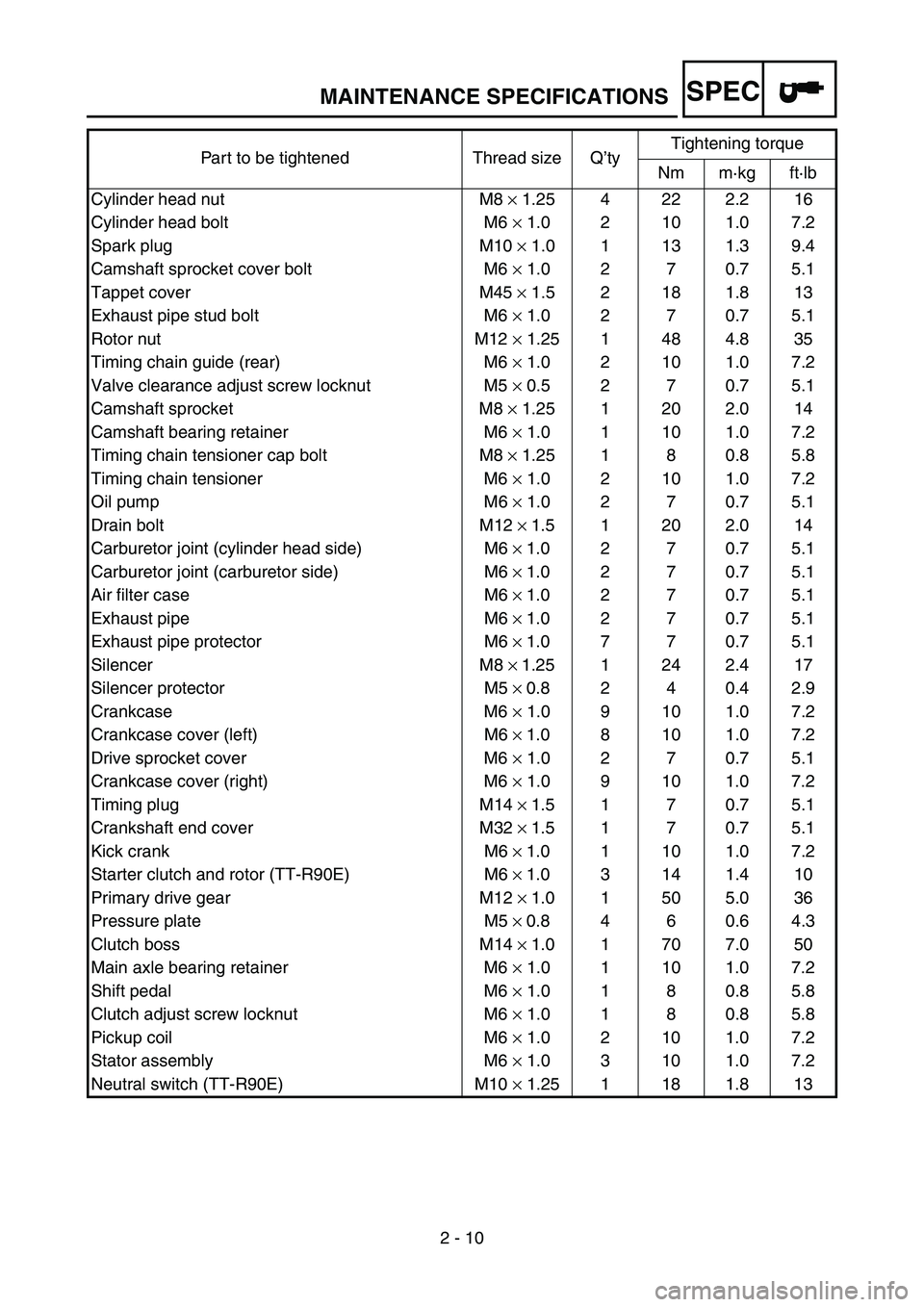
2 - 10 Part to be tightened Thread size Q’tyTightening torque
Nm m·kg ft·lb
Cylinder head nut M8 × 1.25 4 22 2.2 16
Cylinder head bolt M6 × 1.0 2 10 1.0 7.2
Spark plug M10 × 1.0 1 13 1.3 9.4
Camshaft sprocket cover bolt M6 × 1.0 2 7 0.7 5.1
Tappet cover M45 × 1.5 2 18 1.8 13
Exhaust pipe stud bolt M6 × 1.0 2 7 0.7 5.1
Rotor nut M12 × 1.25 1 48 4.8 35
Timing chain guide (rear) M6 × 1.0 2 10 1.0 7.2
Valve clearance adjust screw locknut M5 × 0.5 2 7 0.7 5.1
Camshaft sprocket M8 × 1.25 1 20 2.0 14
Camshaft bearing retainer M6 × 1.0 1 10 1.0 7.2
Timing chain tensioner cap bolt M8 × 1.25 1 8 0.8 5.8
Timing chain tensioner M6 × 1.0 2 10 1.0 7.2
Oil pump M6 × 1.0 2 7 0.7 5.1
Drain bolt M12 ×
1.5 1 20 2.0 14
Carburetor joint (cylinder head side) M6 ×
1.0 2 7 0.7 5.1
Carburetor joint (carburetor side) M6 ×
1.0 2 7 0.7 5.1
Air filter case M6 ×
1.0 2 7 0.7 5.1
Exhaust pipe M6 ×
1.0 2 7 0.7 5.1
Exhaust pipe protector M6 ×
1.0 7 7 0.7 5.1
Silencer M8 ×
1.25 1 24 2.4 17
Silencer protector M5 ×
0.8 2 4 0.4 2.9
Crankcase M6 × 1.0 9 10 1.0 7.2
Crankcase cover (left) M6 ×
1.0 8 10 1.0 7.2
Drive sprocket cover M6 × 1.0 2 7 0.7 5.1
Crankcase cover (right) M6 × 1.0 9 10 1.0 7.2
Timing plug M14 ×
1.5 1 7 0.7 5.1
Crankshaft end cover M32 ×
1.5 1 7 0.7 5.1
Kick crank M6 ×
1.0 1 10 1.0 7.2
Starter clutch and rotor (TT-R90E) M6 ×
1.0 3 14 1.4 10
Primary drive gear M12 ×
1.0 1 50 5.0 36
Pressure plate M5 ×
0.8 4 6 0.6 4.3
Clutch boss M14 ×
1.0 1 70 7.0 50
Main axle bearing retainer M6 × 1.0 1 10 1.0 7.2
Shift pedal M6 × 1.0 1 8 0.8 5.8
Clutch adjust screw locknut M6 × 1.0 1 8 0.8 5.8
Pickup coil M6 × 1.0 2 10 1.0 7.2
Stator assembly M6 × 1.0 3 10 1.0 7.2
Neutral switch (TT-R90E) M10 × 1.25 1 18 1.8 13
MAINTENANCE SPECIFICATIONS
Page 128 of 390
3 - 1
INSP
ADJ
MAINTENANCE INTERVALS
EC300000
REGULAR INSPECTION AND ADJUSTMENTS
MAINTENANCE INTERVALS
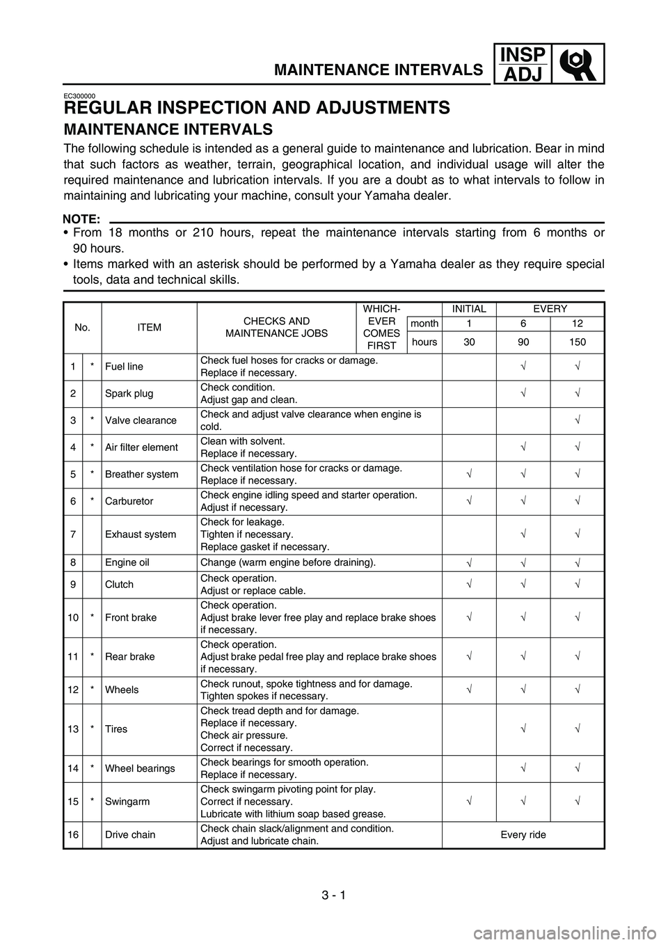
The following schedule is intended as a general guide to maintenance and lubrication. Bear in mind
that such factors as weather, terrain, geographical location, and individual usage will alter the
required maintenance and lubrication intervals. If you are a doubt as to what intervals to follow in
maintaining and lubricating your machine, consult your Yamaha dealer.
NOTE:
From 18 months or 210 hours, repeat the maintenance intervals starting from 6 months or
90 hours.
Items marked with an asterisk should be performed by a Yamaha dealer as they require special
tools, data and technical skills.
No. ITEMCHECKS AND
MAINTENANCE JOBSWHICH-
EVER
COMES
FIRSTINITIAL EVERY
month 1 6 12
hours 30 90 150
1 * Fuel lineCheck fuel hoses for cracks or damage.
Replace if necessary.√
√
2 Spark plugCheck condition.
Adjust gap and clean.√
√
3 * Valve clearanceCheck and adjust valve clearance when engine is
cold.√
4 * Air filter elementClean with solvent.
Replace if necessary.√
√
5 * Breather systemCheck ventilation hose for cracks or damage.
Replace if necessary.√
√
√
6 * CarburetorCheck engine idling speed and starter operation.
Adjust if necessary.√
√
√
7 Exhaust systemCheck for leakage.
Tighten if necessary.
Replace gasket if necessary.√
√
8 Engine oil Change (warm engine before draining).
√
√
√
9 ClutchCheck operation.
Adjust or replace cable.√
√
√
10 * Front brakeCheck operation.
Adjust brake lever free play and replace brake shoes
if necessary.√
√
√
11 * Rear brakeCheck operation.
Adjust brake pedal free play and replace brake shoes
if necessary.√
√
√
12 * WheelsCheck runout, spoke tightness and for damage.
Tighten spokes if necessary.√
√
√
13 * TiresCheck tread depth and for damage.
Replace if necessary.
Check air pressure.
Correct if necessary.√
√
14 * Wheel bearingsCheck bearings for smooth operation.
Replace if necessary.√
√
15 * SwingarmCheck swingarm pivoting point for play.
Correct if necessary.
Lubricate with lithium soap based grease.√
√
√
16 Drive chainCheck chain slack/alignment and condition.
Adjust and lubricate chain.Every ride
3
Page 129 of 390

3 - 2
INSP
ADJ
MAINTENANCE INTERVALS
NOTE:
The air filter needs more frequent service if you are riding in unusually wet or dusty areas.
17 * Steering bearingsCheck bearing assemblies for looseness.
Lubricate with lithium soap based grease every or
120 hours or 12 months (whichever comes first).√
√
18Brake and clutch
lever pivot shaftsApply lithium soap based grease lightly.
√
√
√
19Brake pedal pivot
shaftApply lithium soap based grease lightly.
√
√
√
20 Sidestand pivotCheck operation.
Apply lithium soap based grease lightly.√
√
21 * Front forkCheck operation and for oil leakage.
Replace if necessary.√
√
22 *Shock absorber
assemblyCheck operation and for oil leakage.
Replace if necessary.√
√
23 * Control cablesApply Yamaha chain and cable lube or engine oil
10W-30 thoroughly.√
√
√
24 *Throttle grip hous-
ing and cableCheck operation and free play.
Adjust the throttle cable free play if necessary.
Lubricate the throttle grip housing and cable.√
√
√
25 * Chassis fastenersCheck all chassis fitting and fasteners.
Correct if necessary.√
√
√
26Battery (TT-R90E
only)Check terminal for looseness and corrosion.
√ No. ITEMCHECKS AND
MAINTENANCE JOBSWHICH-
EVER
COMES
FIRSTINITIAL EVERY
month 1 6 12
hours 30 90 150
3
Page 130 of 390
3 - 3
INSP
ADJ
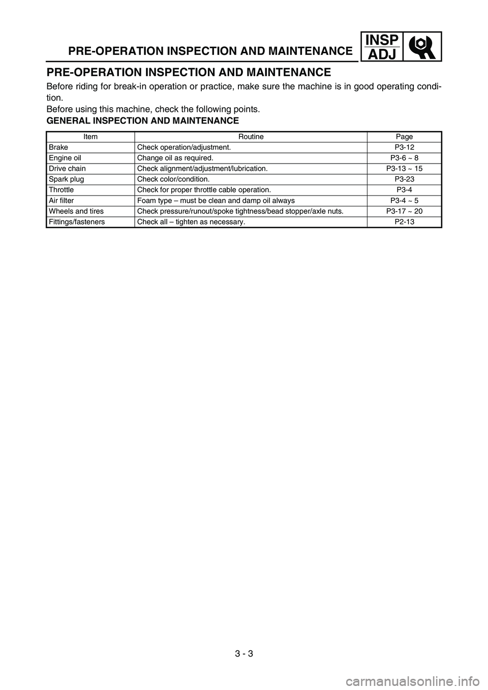
PRE-OPERATION INSPECTION AND MAINTENANCE
PRE-OPERATION INSPECTION AND MAINTENANCE
Before riding for break-in operation or practice, make sure the machine is in good operating condi-
tion.
Before using this machine, check the following points.
GENERAL INSPECTION AND MAINTENANCE
Item Routine Page
Brake Check operation/adjustment. P3-12
Engine oil Change oil as required. P3-6 ~ 8
Drive chain Check alignment/adjustment/lubrication. P3-13 ~ 15
Spark plug Check color/condition. P3-23
Throttle Check for proper throttle cable operation. P3-4
Air filter Foam type – must be clean and damp oil always P3-4 ~ 5
Wheels and tires Check pressure/runout/spoke tightness/bead stopper/axle nuts. P3-17 ~ 20
Fittings/fasteners Check all – tighten as necessary. P2-13
Page 140 of 390
3 - 5
INSP
ADJ
AIR FILTER CLEANING
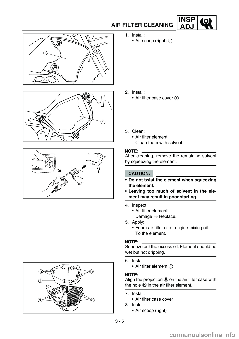
1. Install:
Air scoop (right) 1
2. Install:
Air filter case cover 1
3. Clean:
Air filter element
Clean them with solvent.
NOTE:
After cleaning, remove the remaining solvent
by squeezing the element.
CAUTION:
Do not twist the element when squeezing
the element.
Leaving too much of solvent in the ele-
ment may result in poor starting.
4. Inspect:
Air filter element
Damage → Replace.
5. Apply:
Foam-air-filter oil or engine mixing oil
To the element.
NOTE:
Squeeze out the excess oil. Element should be
wet but not dripping.
6. Install:
Air filter element 1
NOTE:
Align the projection a on the air filter case with
the hole b in the air filter element.
7. Install:
Air filter case cover
8. Install:
Air scoop (right)
Page 266 of 390
4 - 36
ENGOIL PUMP
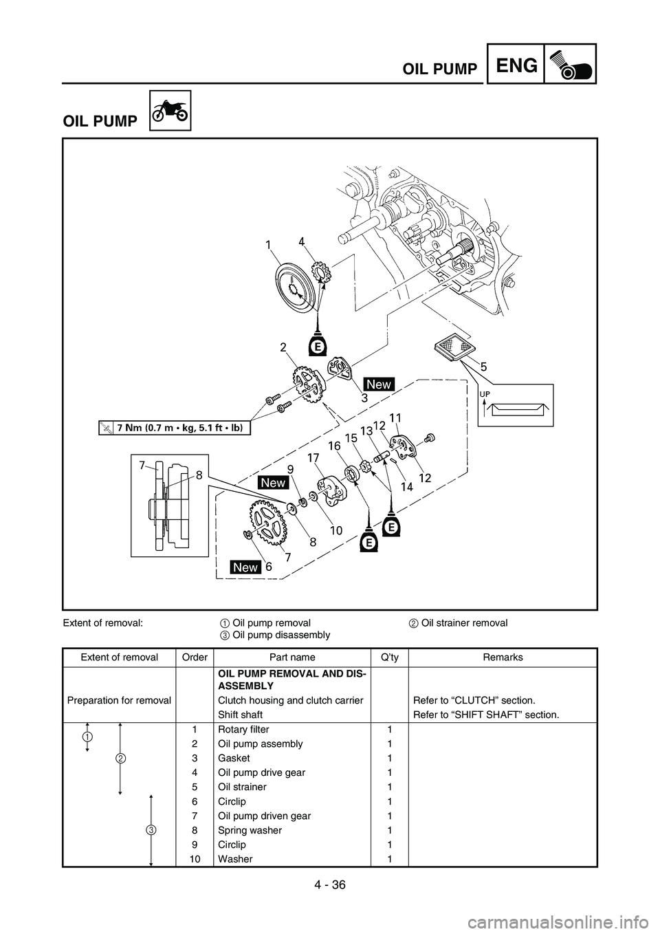
OIL PUMP
Extent of removal:
1 Oil pump removal
2 Oil strainer removal
3 Oil pump disassembly
Extent of removal Order Part name Q’ty Remarks
OIL PUMP REMOVAL AND DIS-
ASSEMBLY
Preparation for removal Clutch housing and clutch carrier Refer to “CLUTCH” section.
Shift shaft Refer to “SHIFT SHAFT” section.
1 Rotary filter 1
2 Oil pump assembly 1
3 Gasket 1
4 Oil pump drive gear 1
5 Oil strainer 1
6 Circlip 1
7 Oil pump driven gear 1
8 Spring washer 1
9 Circlip 1
10 Washer 1
2
1
3
Page 270 of 390

4 - 38
ENGOIL PUMP
INSPECTION
Oil pump
1. Measure:
Tip clearance a
(between the inner rotor 1 and the outer
rotor 2)
Side clearance b
(between the outer rotor 2 and the rotor
housing 3)
Out of specification → Replace the oil
pump assembly.
Rotor housing and rotor clearance c
(between the rotor housing 3 and the
rotors 1 2)
Out of specification → Replace the oil
pump assembly.
Tip clearance
a:
0.15 mm (0.0059 in)
Side clearance
b:
0.13 ~ 0.18 mm
(0.0051 ~ 0.0071 in)
Rotor housing and rotor clear-
ance
c:
0.06 ~ 0.10 mm
(0.0024 ~ 0.0039 in)
Rotary filter and oil strainer
1. Inspect:
Rotary filter 1
Oil strainer 2
Damage → Replace.
3Upper side
4Lower side
ASSEMBLY AND INSTALLATION
Rotary filter
1. Install:
Rotary filter 1
NOTE:
When installing the rotary filter, align the match
mark a on the rotary filter with the hole b of
the crankshaft.
Page 284 of 390

4 - 45
ENGCRANKCASE AND CRANKSHAFT
CRANKCASE AND CRANKSHAFT
Extent of removal Order Part name Q’ty Remarks
CRANKCASE SEPARATION
AND CRANKSHAFT REMOVAL
Preparation for removal Seat, fuel tank and rear fender
Exhaust pipe
Air filter case
Carburetor Refer to “CARBURETOR” section.
Drain the engine oil Refer to “ENGINE OIL REPLACEMENT”
section in the CHAPTER 3.
Engine guard and drive sprocket
Engine assembly From the chassis.
Cylinder head Refer to “CYLINDER HEAD” section.
Cylinder and piston Refer to “CYLINDER AND PISTON” sec-
tion.
Clutch housing and clutch carrier Refer to “CLUTCH” section.
Kick axle assembly Refer to “KICK AXLE” section.