key YAMAHA TW125 2003 Owners Manual
[x] Cancel search | Manufacturer: YAMAHA, Model Year: 2003, Model line: TW125, Model: YAMAHA TW125 2003Pages: 88, PDF Size: 1.71 MB
Page 3 of 88

EAU00005
IMPORTANT MANUAL INFORMATION
Particularly important information is distinguished in this manual by the following notations:
The Safety Alert Symbol means ATTENTION! BECOME ALERT! YOUR SAFETY
IS INVOLVED!
Failure to follow WARNING instructions could result in severe injury or death
to the motorcycle operator, a bystander, or a person inspecting or repairing
the motorcycle.
A CAUTION indicates special precautions that must be taken to avoid damage
to the motorcycle.
A NOTE provides key information to make procedures easier or clearer.
Q
w
cC
NOTE:
NOTE:
8This manual should be considered a permanent part of this motorcycle and should remain
with it even if the motorcycle is subsequently sold.
8Yamaha continually seeks advancements in product design and quality. Therefore, while this
manual contains the most current product information available at the time of printing, there
may be minor discrepancies between your motorcycle and this manual. If you have any ques-
tions concerning this manual, please consult your Yamaha dealer.
5RS-9-E1 (TW125) 8/23/02 11:37 AM Page 2
Page 7 of 88

Adjusting the throttle cable free play .............6-15
Adjusting the valve clearance .......................6-16
Tires ..............................................................6-16
Spoke wheels ................................................6-18
Adjusting the clutch lever free play ...............6-19
Adjusting the brake lever free play ................6-20
Adjusting the brake pedal position and
free play .....................................................6-21
Adjusting the rear brake light switch .............6-22
Checking the front brake pads and
rear brake shoes ........................................6-23
Checking the brake fluid level .......................6-24
Changing the brake fluid ...............................6-25
Drive chain slack ...........................................6-25
Lubricating the drive chain ............................6-27
Checking and lubricating the cables .............6-27
Checking and lubricating the throttle grip
and cable ....................................................6-28
Checking and lubricating the brake and
shift pedals .................................................6-28
Checking and lubricating the brake and
clutch levers ...............................................6-29
Checking and lubricating the sidestand ........6-29
Lubricating the rear suspension ....................6-30
Checking the front fork ..................................6-30
Checking the steering ...................................6-31
Checking the wheel bearings ........................6-31Battery ...........................................................6-32
Replacing the fuse ........................................6-33
Replacing the headlight bulb .........................6-34
Replacing a turn signal light bulb ..................6-36
Replacing the tail/brake light bulb .................6-36
Supporting the motorcycle ............................6-37
Front wheel ...................................................6-38
Rear wheel ....................................................6-40
Troubleshooting ............................................6-42
Troubleshooting chart ...................................6-43
MOTORCYCLE CARE AND STORAGE ............7-1
Care ................................................................7-1
Storage ............................................................7-4
SPECIFICATIONS .............................................8-1
Specifications ..................................................8-1
Conversion table .............................................8-5
CONSUMER INFORMATION ............................9-1
Identification numbers .....................................9-1
Key identification number ................................9-1
Vehicle identification number ..........................9-1
Model label ......................................................9-2
TABLE OF CONTENTS
7
8
9
5RS-9-E1 (TW125) 8/23/02 11:37 AM Page 6
Page 12 of 88

3-1
EAU00027
INSTRUMENT AND CONTROL FUNCTIONS
3
EAU00028
Main switch
The main switch controls the ignition
and lighting systems. The various
main switch positions are described
below.
EAU04926
ON
All electrical circuits are supplied with
power; the meter lighting, taillight and
auxiliary light come on, and the
engine can be started. The key can-
not be removed.
OFFON
EAU00056
Indicator lightsEAU00057
Turn signal indicator light “5”
This indicator light flashes when the
turn signal switch is pushed to the left
or right.
EAU00063
High beam indicator light “&”
This indicator light comes on when
the high beam of the headlight is
switched on.
312
1. Turn signal indicator light “5”
2. High beam indicator light “&”
3. Neutral indicator light “N”
NOTE:
The headlight comes on automatical-
ly when the engine is started and
stays on until the key is turned to
“OFF”.
EAU00038
OFF
All electrical systems are off. The key
can be removed.
5RS-9-E1 (TW125) 8/23/02 11:37 AM Page 11
Page 16 of 88

3-5
INSTRUMENT AND CONTROL FUNCTIONS
3
EAU00158
Brake lever
The brake lever is located at the right
handlebar grip. To apply the front
brake, pull the lever toward the han-
dlebar grip.
1
1. Brake lever
EAU00162
Brake pedal
The brake pedal is on the right side
of the motorcycle. To apply the rear
brake, press down on the brake
pedal.
1
1. Brake pedal
EAU00177*
Fuel tank cap
To remove the fuel tank cap
1. Insert the key into the lock and
turn it 1/3 turn counterclockwise.
2. Turn the fuel tank cap 1/3 turn
counterclockwise and pull it off.
1
a
1. Fuel tank cap
a. Unlock.
5RS-9-E1 (TW125) 8/23/02 11:37 AM Page 15
Page 17 of 88

3-6
To install the fuel tank cap
1. Insert the fuel tank cap into the
tank opening with the key insert-
ed in the lock, and then turn the
cap 1/3 turn clockwise.
2. Turn the key 1/3 turn clockwise,
and then remove it.
NOTE:
The fuel tank cap cannot be installed
unless the key is in the lock. In addi-
tion, the key cannot be removed if the
cap is not properly installed and
locked.
EW000023
w
Make sure that the fuel tank cap is
properly closed and locked before
riding.
INSTRUMENT AND CONTROL FUNCTIONS
3
EAU03753
Fuel
Make sure that there is sufficient fuel
in the tank. Fill the fuel tank to the
bottom of the filler tube as shown.
EW000130
w
8Do not overfill the fuel tank,
otherwise it may overflow
when the fuel warms up and
expands.
8Avoid spilling fuel on the hot
engine.
1
2
1. Filler tube
2. Fuel level
EAU00185
cC
Immediately wipe off spilled fuel
with a clean, dry, soft cloth, since
fuel may deteriorate painted sur-
faces or plastic parts.
EAU04284
Recommended fuel:
REGULAR UNLEADED
GASOLINE ONLY
Fuel tank capacity:
Total amount:
7.0 L
Reserve amount:
1.7 L
5RS-9-E1 (TW125) 8/23/02 11:37 AM Page 16
Page 19 of 88

3-8
RES
This indicates reserve. If you run out
of fuel while riding, move the lever to
this position. Fill the tank at the first
opportunity. Be sure to set the lever
back to “ON” after refueling!
INSTRUMENT AND CONTROL FUNCTIONS
3
OFF
ONFUEL RES
1
RES
1. Arrow mark positioned over “RES”
EAU04038
Starter (choke) knob“1”
Starting a cold engine requires a rich-
er air-fuel mixture, which is supplied
by the starter (choke).
Move the knob in direction ato turn
on the starter (choke).
Move the knob in direction bto turn
off the starter (choke).
a
b
1
1. Starter (choke) knob “1”
EAU03342
Steering lock
To lock the steering
1. Turn the handlebar all the way to
the right.
2. Open the steering lock cover,
and then insert the steering lock
key.
3. Turn the key 1/8 turn counter-
clockwise, push it in while turning
the handlebar slightly to the left,
and then turn the key 1/8 turn
clockwise.
21
1. Steering lock cover
2. Steering lock
RES: Reserve position
5RS-9-E1 (TW125) 8/23/02 11:37 AM Page 18
Page 20 of 88

3-9
INSTRUMENT AND CONTROL FUNCTIONS
3 4. Check that the steering is locked,
remove the key, and then close
the lock cover.
To unlock the steering
1. Open the steering lock cover,
and then insert the steering lock
key.
2. Push the key in, turn it 1/8 turn
counterclockwise so that it
moves out, and then release it.
3. Remove the key, and then close
the lock cover.
EAU01092
Seat
To remove the seat
Remove the bolts, and then pull the
seat off.
1
1. Bolt (×2)
To install the seat
1. Insert the projection on the front
of the seat into the seat holder
as shown.
2. Place the seat in the original
position, and then tighten the
bolts.
NOTE:
Make sure that the seat is properly
secured before riding.
12
1. Projection
2. Seat holder
5RS-9-E1 (TW125) 8/23/02 11:37 AM Page 19
Page 21 of 88

3-10
EAU00260
Helmet holder
To open the helmet holder, insert the
key into the lock, and then turn the
key as shown.
To lock the helmet holder, place it in
the original position, and then remove
the key.
EW000030
w
Never ride with a helmet attached
to the helmet holder, since the hel-
met may hit objects, causing loss
of control and possibly an acci-
dent.
INSTRUMENT AND CONTROL FUNCTIONS
3
1
1. Helmet holder
EAU01343
Shock absorberEAU00315
w
This shock absorber contains high-
ly pressurized nitrogen gas. For
proper handling, read and under-
stand the following information
before handling the shock
absorber. The manufacturer cannot
be held responsible for property
damage or personal injury that may
result from improper handling.
8Do not tamper with or attempt
to open the gas cylinder.
8Do not subject the shock
absorber to an open flame or
other high heat sources, other-
wise it may explode due to
excessive gas pressure.
8Do not deform or damage the
gas cylinder in any way, as
this will result in poor damp-
ing performance.
8Always have a Yamaha dealer
service the shock absorber.
EAU00320
CarrierEW000032
w
8Do not exceed the load limit of
3 kg for the carrier.
8Do not exceed the maximum
load of 180 kg for the vehicle.
1
1. Carrier
5RS-9-E1 (TW125) 8/23/02 11:37 AM Page 20
Page 24 of 88

3-13
INSTRUMENT AND CONTROL FUNCTIONS
3
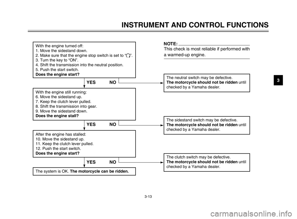
With the engine turned off:
1. Move the sidestand down.
2. Make sure that the engine stop switch is set to “
#”.
3. Turn the key to “ON”.
4. Shift the transmission into the neutral position.
5. Push the start switch.
Does the engine start?
The neutral switch may be defective.
The motorcycle should not be ridden until
checked by a Yamaha dealer.
With the engine still running:
6. Move the sidestand up.
7. Keep the clutch lever pulled.
8. Shift the transmission into gear.
9. Move the sidestand down.
Does the engine stall?
After the engine has stalled:
10. Move the sidestand up.
11. Keep the clutch lever pulled.
12. Push the start switch.
Does the engine start?
The sidestand switch may be defective.
The motorcycle should not be ridden until
checked by a Yamaha dealer.
The clutch switch may be defective.
The motorcycle should not be ridden until
checked by a Yamaha dealer.
NO
NOTE:
This check is most reliable if performed with
a warmed-up engine.
YES
YES NO
The system is OK. The motorcycle can be ridden.
YES NO
5RS-9-E1 (TW125) 8/23/02 11:37 AM Page 23
Page 28 of 88

5-1
EAU00372
OPERATION AND IMPORTANT RIDING POINTS
5
EAU00373
w
8Become thoroughly familiar
with all operating controls and
their functions before riding.
Consult a Yamaha dealer
regarding any control or func-
tion that you do not thorough-
ly understand.
8Never start the engine or oper-
ate it in a closed area for any
length of time. Exhaust fumes
are poisonous, and inhaling
them can cause loss of con-
sciousness and death within a
short time. Always make sure
that there is adequate ventila-
tion.
8Before starting out, make sure
that the sidestand is up. If the
sidestand is not raised com-
pletely, it could contact the
ground and distract the opera-
tor, resulting in a possible loss
of control.
EAU04692
Starting a cold engine
In order for the ignition circuit cut-off
system to enable starting, one of the
following conditions must be met:
8The transmission is in the neutral
position.
8The transmission is in gear with
the clutch lever pulled and the
sidestand up.
EW000054
w
8Before starting the engine,
check the function of the igni-
tion circuit cut-off system
according to the procedure
described on page 3-13.
8Never ride with the sidestand
down.
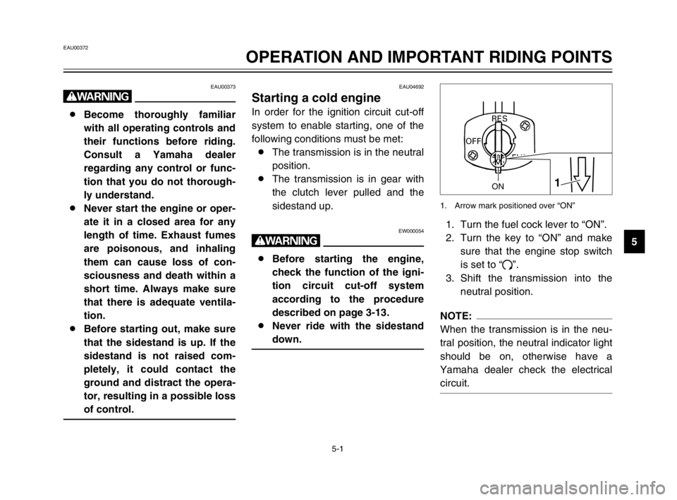
1. Turn the fuel cock lever to “ON”.
2. Turn the key to “ON” and make
sure that the engine stop switch
is set to “#”.
3. Shift the transmission into the
neutral position.
NOTE:
When the transmission is in the neu-
tral position, the neutral indicator light
should be on, otherwise have a
Yamaha dealer check the electrical
circuit.
ONFUEL
RES
OFF
1ON
1. Arrow mark positioned over “ON”
5RS-9-E1 (TW125) 8/23/02 11:37 AM Page 27