YAMAHA VIKING VI 2016 Owners Manual
Manufacturer: YAMAHA, Model Year: 2016, Model line: VIKING VI, Model: YAMAHA VIKING VI 2016Pages: 184, PDF Size: 4.39 MB
Page 141 of 184
8-32
8
13. Thoroughly apply Yamaha foam air filteroil or other quality liquid foam air filter oil
(not spray type) to the sponge material.
The sponge material should be wet but
not dripping.
14. Pull the sponge material over its frame.
15. Install the air filt er element holder.
16. Install the air filter element.
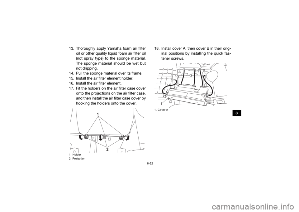
17. Fit the holders on the air filter case cover
onto the projections on the air filter case,
and then install the air filter case cover by
hooking the holders onto the cover. 18. Install cover A, then cover B in their orig-
inal positions by installing the quick fas-
tener screws.1. Holder
2. Projection
1
2
1. Cover A
1
UB857AE0.book Page 32 Monday, August 24, 2015 8:59 AM
Page 142 of 184
8-33
8
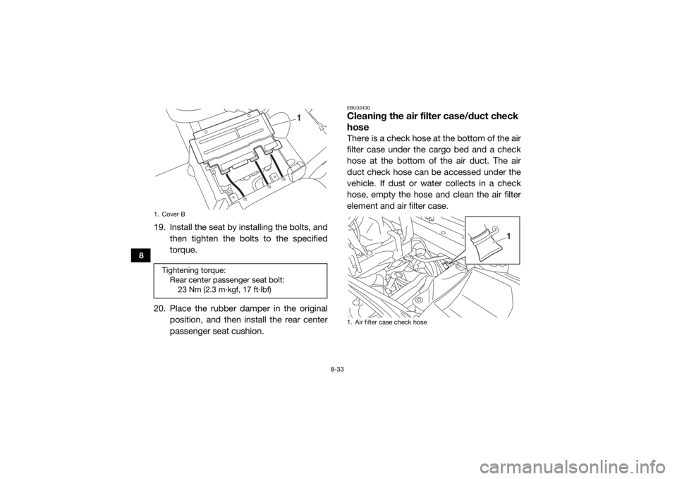
19. Install the seat by installing the bolts, and
then tighten the bolts to the specified
torque.
20. Place the rubber damper in the original position, and then install the rear center
passenger seat cushion.
EBU32430Cleaning the air filter case/duct check
hoseThere is a check hose at the bottom of the air
filter case under the cargo bed and a check
hose at the bottom of the air duct. The air
duct check hose can be accessed under the
vehicle. If dust or water collects in a check
hose, empty the hose and clean the air filter
element and air filter case.
1. Cover BTightening torque:Rear center passenger seat bolt:23 Nm (2.3 m·kgf, 17 ft·lbf)
1
1. Air filter case check hose
1
UB857AE0.book Page 33 Monday, August 24, 2015 8:59 AM
Page 143 of 184
8-34
8
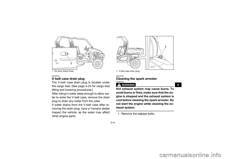
EBU32440V-belt case drain plugThe V-belt case drain plug is located under
the cargo bed. (See page 4-24 for cargo bed
lifting and lowering procedures.)
After riding in water deep enough to allow wa-
ter to enter the V-belt case, remove the drain
plug to drain any water from the case.
If water drains from the V-belt case after re-
moving the drain plug, have a Yamaha dealer
inspect the vehicle, as the water may affect
other engine parts.
EBU32450Cleaning the spark arrester
WARNING
EWB03370Hot exhaust system may cause burns. To
avoid burns or fires, make sure that the en-
gine is stopped and the exhaust system is
cool before cleaning the spark arrester. Do
not start the engine while cleaning the ex-
haust system. 1. Remove the tailpipe bolts.
1. Air duct check hose
1
1. V-belt case drain plug
1
UB857AE0.book Page 34 Monday, August 24, 2015 8:59 AM
Page 144 of 184
8-35
8
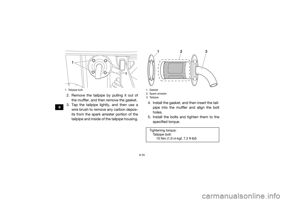
2. Remove the tailpipe by pulling it out ofthe muffler, and then remove the gasket.
3. Tap the tailpipe lightly, and then use a
wire brush to remove any carbon depos-
its from the spark arrester portion of the
tailpipe and inside of the tailpipe housing. 4. Install the gasket, and then insert the tail-
pipe into the muffler and align the bolt
holes.
5. Install the bolts and tighten them to the
specified torque.1. Tailpipe bolt
1
1
1. Gasket
2. Spark arrester
3. TailpipeTightening torque:
Tailpipe bolt:10 Nm (1.0 m·kgf, 7.2 ft·lbf)
3
2
1
UB857AE0.book Page 35 Monday, August 24, 2015 8:59 AM
Page 145 of 184
8-36
8
EBU32460Valve clearanceThe correct valve clearance changes with
use, resulting in improper fuel/air supply or
engine noise. To prevent this, the valve clear-
ance must be adjusted regularly. This adjust-
ment however, should be left to a
professional Yamaha service technician.EBU32470BrakesReplacement of brake components requires
professional knowledge. Brake service
should be performed by a Yamaha dealer.
WARNING
EWB02572Operating with improperly serviced or ad-
justed brakes could lead to a loss in brak-
ing ability and an accident.
EBU32480Checking the front and rear brake padsEach brake pad is prov ided with wear indica-
tor grooves, which allow you to check the
brake pad wear without having to disassem-
ble the brake. To check the brake pad wear,
check the wear indicator grooves. If a brake
pad has worn to the point that the wear indi-
cator grooves have almost disappeared, have
a Yamaha dealer replace the brake pads as a
set.
The wheels need to be removed to check the
brake pads. (See page s 8-43, 8-45 for wheel
removal and installation procedures.)
UB857AE0.book Page 36 Monday, August 24, 2015 8:59 AM
Page 146 of 184
8-37
8
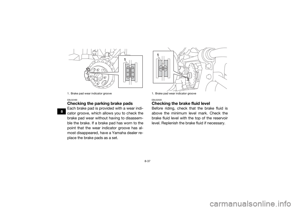
EBU32490Checking the parking brake padsEach brake pad is provided with a wear indi-
cator groove, which allows you to check the
brake pad wear without having to disassem-
ble the brake. If a brake pad has worn to the
point that the wear indicator groove has al-
most disappeared, have a Yamaha dealer re-
place the brake pads as a set.
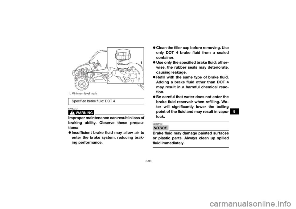
EBU32500Checking the brake fluid levelBefore riding, check that the brake fluid is
above the minimum level mark. Check the
brake fluid level with the top of the reservoir
level. Replenish the brake fluid if necessary.
1. Brake pad wear indicator groove
1
1. Brake pad wear indicator groove
1
UB857AE0.book Page 37 Monday, August 24, 2015 8:59 AM
Page 147 of 184
8-38
8
WARNING
EWB02721Improper maintenance can result in loss of
braking ability. Observe these precau-
tions:
Insufficient brake fluid may allow air to
enter the brake system, reducing brak-
ing performance.
Clean the filler cap before removing. Use
only DOT 4 brake fluid from a sealed
container.
Use only the specified brake fluid; other-
wise, the rubber seal s may deteriorate,
causing leakage.
Refill with the same type of brake fluid.
Adding a brake fluid other than DOT 4
may result in a harmful chemical reac-
tion.
Be careful that water does not enter the
brake fluid reservoir when refilling. Wa-
ter will significantly lower the boiling
point of the fluid and may result in vapor
lock.
NOTICEECB01161Brake fluid may damage painted surfaces
or plastic parts. Always clean up spilled
fluid immediately.
1. Minimum level markSpecified brake fluid: DOT 4
1
UB857AE0.book Page 38 Monday, August 24, 2015 8:59 AM
Page 148 of 184
8-39
8
As the brake pads wear, it is normal for the
brake fluid level to gradually go down. A low
brake fluid level may indicate worn brake
pads and/or brake system leakage; therefore,
be sure to check the brake pads for wear and
the brake system for leakage. If the brake fluid
level goes down suddenly, have a Yamaha
dealer check the cause before further riding.EBU32520Brake fluid replacementComplete fluid replacement should be done
only by trained Yamaha service personnel.
Have a Yamaha dealer replace the following
components during periodic maintenance or
when they are damaged or leaking.
Replace the oil seals every two years.
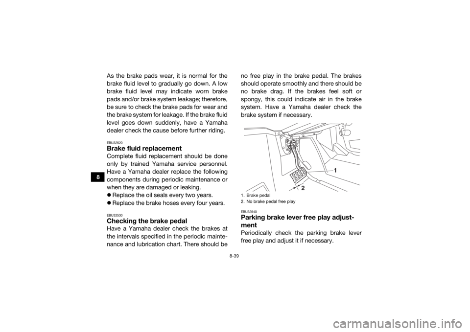
Replace the brake hoses every four years.EBU32530Checking the brake pedalHave a Yamaha dealer check the brakes at
the intervals specified in the periodic mainte-
nance and lubrication chart. There should be no free play in the brake pedal. The brakes
should operate smoothly and there should be
no brake drag. If the brakes feel soft or
spongy, this could indicate air in the brake
system. Have a Yamaha dealer check the
brake system if necessary.
EBU32540Parking brake lever free play adjust-
mentPeriodically check th
e parking brake lever
free play and adjust it if necessary.1. Brake pedal
2. No brake pedal free play
1
2
UB857AE0.book Page 39 Monday, August 24, 2015 8:59 AM
Page 149 of 184
8-40
8
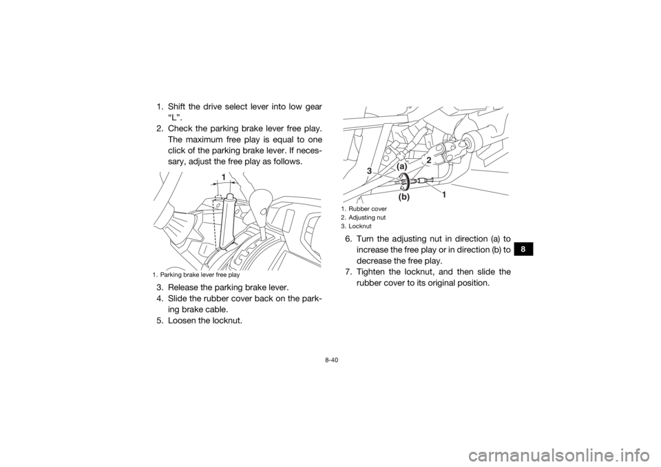
1. Shift the drive select lever into low gear“L”.
2. Check the parking brake lever free play. The maximum free play is equal to one
click of the parking brake lever. If neces-
sary, adjust the free play as follows.
3. Release the parking brake lever.
4. Slide the rubber cover back on the park- ing brake cable.
5. Loosen the locknut. 6. Turn the adjusting nut in direction (a) to
increase the free play or in direction (b) to
decrease the free play.
7. Tighten the locknut, and then slide the
rubber cover to its original position.1. Parking brake lever free play
1
1. Rubber cover
2. Adjusting nut
3. Locknut
1
(a)
(b)
2
3
UB857AE0.book Page 40 Monday, August 24, 2015 8:59 AM
Page 150 of 184
8-41
8
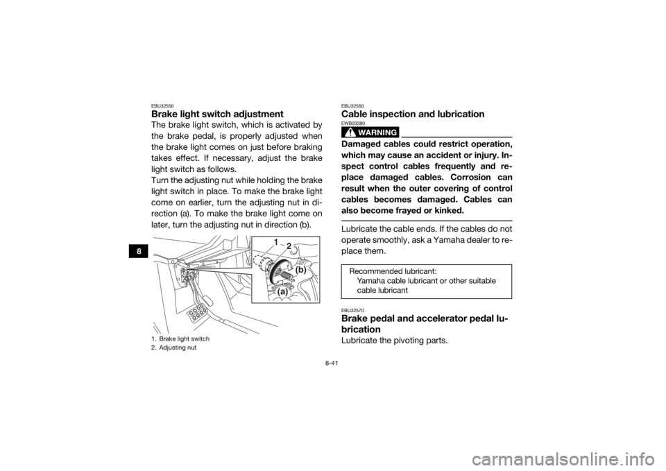
EBU32550Brake light switch adjustmentThe brake light switch, which is activated by
the brake pedal, is properly adjusted when
the brake light comes on just before braking
takes effect. If necessary, adjust the brake
light switch as follows.
Turn the adjusting nut while holding the brake
light switch in place. To make the brake light
come on earlier, turn the adjusting nut in di-
rection (a). To make the brake light come on
later, turn the adjusting nut in direction (b).
EBU32560Cable inspection and lubrication
WARNING
EWB03380Damaged cables could restrict operation,
which may cause an accident or injury. In-
spect control cables frequently and re-
place damaged cables. Corrosion can
result when the outer covering of control
cables becomes damaged. Cables can
also become frayed or kinked. Lubricate the cable ends. If the cables do not
operate smoothly, ask a Yamaha dealer to re-
place them.EBU32570Brake pedal and accelerator pedal lu-
bricationLubricate the pivoting parts.
1. Brake light switch
2. Adjusting nut
1(a)
(b)
2
Recommended lubricant:Yamaha cable lubricant or other suitable cable lubricant
UB857AE0.book Page 41 Monday, August 24, 2015 8:59 AM