lock YAMAHA VMAX 2001 Owners Manual
[x] Cancel search | Manufacturer: YAMAHA, Model Year: 2001, Model line: VMAX, Model: YAMAHA VMAX 2001Pages: 110, PDF Size: 11.88 MB
Page 15 of 110
3
INSTRUMENT AND CONTROL FUNCTIONS
Main switch .......................................................... 3-1
Indicator and warning lights ................................ 3-1
Speedometer unit ................................................ 3-2
Tachometer .......................................................... 3-3
Anti-theft alarm (optional) .................................... 3-3
Coolant temperature gauge ................................. 3-3
Handlebar switches ............................................. 3-4
Clutch lever .......................................................... 3-5
Shift pedal ............................................................ 3-6
Brake lever ........................................................... 3-6
Brake pedal .......................................................... 3-6
Fuel tank cap ....................................................... 3-7Fuel ..................................................................... 3-8
Starter (choke) lever ............................................ 3-8
Steering lock ....................................................... 3-9
Rider seat ............................................................ 3-9
Helmet holder .................................................... 3-10
Adjusting the front fork ...................................... 3-11
Adjusting the shock absorber assemblies ......... 3-12
Matching the front and rear suspension
settings ............................................................ 3-15
Sidestand .......................................................... 3-16
Ignition circuit cut-off system ............................. 3-16
E_3lr.book Page 1 Wednesday, November 22, 2000 4:10 PM
Page 22 of 110
INSTRUMENT AND CONTROL FUNCTIONS
3-7
3
EAU01654
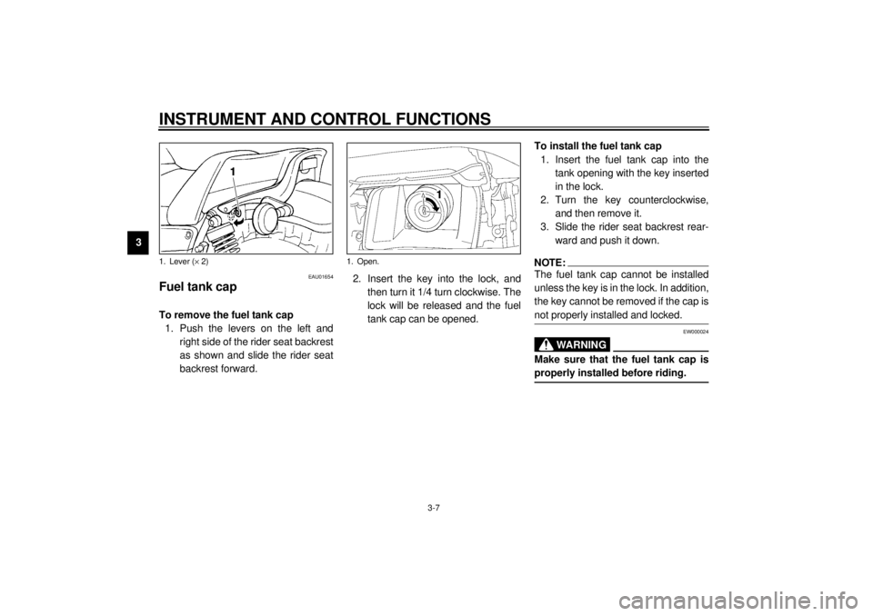
Fuel tank cap To remove the fuel tank cap
1. Push the levers on the left and
right side of the rider seat backrest
as shown and slide the rider seat
backrest forward.2. Insert the key into the lock, and
then turn it 1/4 turn clockwise. The
lock will be released and the fuel
tank cap can be opened.To install the fuel tank cap
1. Insert the fuel tank cap into the
tank opening with the key inserted
in the lock.
2. Turn the key counterclockwise,
and then remove it.
3. Slide the rider seat backrest rear-
ward and push it down.
NOTE:@ The fuel tank cap cannot be installed
unless the key is in the lock. In addition,
the key cannot be removed if the cap is
not properly installed and locked. @
EW000024
WARNING
@ Make sure that the fuel tank cap is
properly installed before riding. @
1. Lever (´ 2)
1. Open.
E_3lr.book Page 7 Wednesday, November 22, 2000 4:10 PM
Page 24 of 110
INSTRUMENT AND CONTROL FUNCTIONS
3-9
3
EAU03342
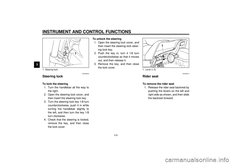
Steering lock To lock the steering
1. Turn the handlebar all the way to
the right.
2. Open the steering lock cover, and
then insert the steering lock key.
3. Turn the steering lock key 1/8 turn
counterclockwise, push it in while
turning the handlebar slightly to
the left, and then turn the key 1/8
turn clockwise.
4. Check that the steering is locked,
remove the key, and then close
the lock cover.To unlock the steering
1. Open the steering lock cover, and
then insert the steering lock steer-
ing lock key.
2. Push the key in, turn it 1/8 turn
counterclockwise so that it moves
out, and then release it.
3. Remove the key, and then close
the lock cover.
EAU03413
Rider seat To remove the rider seat
1. Release the rider seat backrest by
pushing the levers on the left and
right side as shown, and then slide
the backrest forward.
1. Steering lock
1. Lever (´ 2)
E_3lr.book Page 9 Wednesday, November 22, 2000 4:10 PM
Page 25 of 110
INSTRUMENT AND CONTROL FUNCTIONS
3-10
3
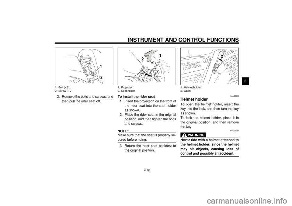
2. Remove the bolts and screws, and
then pull the rider seat off.To install the rider seat
1. Insert the projection on the front of
the rider seat into the seat holder
as shown.
2. Place the rider seat in the original
position, and then tighten the bolts
and screws.
NOTE:@ Make sure that the seat is properly se-
cured before riding. @3. Return the rider seat backrest to
the original position.
EAU00260
Helmet holder To open the helmet holder, insert the
key into the lock, and then turn the key
as shown.
To lock the helmet holder, place it in
the original position, and then remove
the key.
EW000030
WARNING
@ Never ride with a helmet attached to
the helmet holder, since the helmet
may hit objects, causing loss of
control and possibly an accident. @
1. Bolt (´ 2)
2. Screw (´ 2)
1. Projection
2. Seat holder
1. Helmet holder
2. Open.
E_3lr.book Page 10 Wednesday, November 22, 2000 4:10 PM
Page 49 of 110
PERIODIC MAINTENANCE AND MINOR REPAIR
6-6
6
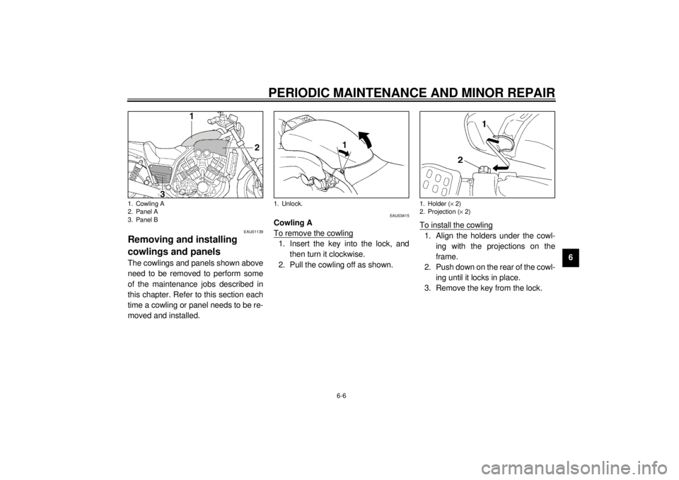
EAU01139
Removing and installing
cowlings and panels The cowlings and panels shown above
need to be removed to perform some
of the maintenance jobs described in
this chapter. Refer to this section each
time a cowling or panel needs to be re-
moved and installed.
EAU03415
Cowling A
To remove the cowling1. Insert the key into the lock, and
then turn it clockwise.
2. Pull the cowling off as shown.To install the cowling
1. Align the holders under the cowl-
ing with the projections on the
frame.
2. Push down on the rear of the cowl-
ing until it locks in place.
3. Remove the key from the lock.
1. Cowling A
2. Panel A
3. Panel B
1. Unlock.
1. Holder (´ 2)
2. Projection (´ 2)
E_3lr.book Page 6 Wednesday, November 22, 2000 4:10 PM
Page 60 of 110
PERIODIC MAINTENANCE AND MINOR REPAIR
6-17
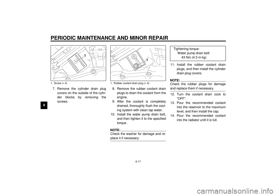
67. Remove the cylinder drain plug
covers on the outside of the cylin-
der blocks by removing the
screws.8. Remove the rubber coolant drain
plugs to drain the coolant from the
engine.
9. After the coolant is completely
drained, thoroughly flush the cool-
ing system with clean tap water.
10. Install the water pump drain bolt,
and then tighten it to the specified
torque.
NOTE:@ Check the washer for damage and re-
place it if necessary. @
11. Install the rubber coolant drain
plugs, and then install the cylinder
drain plug covers.NOTE:@ Check the rubber plugs for damage
and replace them if necessary. @12. Turn the coolant drain cock to
“OFF”.
13. Pour the recommended coolant
into the reservoir to the maximum
level, and then install the cap.
14. Pour the recommended coolant
into the radiator until it is full.
1. Screw (´ 4)
1. Rubber coolant drain plug (´ 4)
Tightening torque:
Water pump drain bolt:
43 Nm (4.3 m·kg)
E_3lr.book Page 17 Wednesday, November 22, 2000 4:10 PM
Page 67 of 110

PERIODIC MAINTENANCE AND MINOR REPAIR
6-24
6
EAU00689
Cast wheels To maximize the performance, durabil-
ity, and safe operation of your motor-
cycle, note the following points
regarding the specified wheels.l
The wheel rims should be checked
for cracks, bends, warpage or
damage before each ride. If any
damage is found, have a Yamaha
dealer replace the wheel. Do not
attempt even the smallest repair to
the wheel. A deformed or cracked
wheel must be replaced.
l
The wheel should be balanced
whenever either the tire or wheel
has been changed or replaced. An
unbalanced wheel can result in
poor performance, adverse han-
dling characteristics, and a short-
ened tire life.
l
Ride at moderate speeds after
changing a tire since the tire sur-
face must first be “broken in” for it
to develop its optimal characteris-
tics.
l
After repairing or replacing a tire,
tighten the valve stem nut and
locknut to the specified torques.
EAU00695
Clutch lever free play Since this model is equipped with a hy-
draulic clutch, adjusting the clutch lever
free play is not needed. However, it is
necessary to check the clutch fluid lev-
el and check the hydraulic system for
leakage before each ride. If the clutch
lever free play does become exces-
sive, and shifting becomes rough or
clutch slippage occurs, causing poor
acceleration, there may be air in the
clutch system. If there is air in the hy-
draulic system, have a Yamaha dealer
bleed the system before operating the
motorcycle. Tightening torques:
Valve stem nut:
1.6 Nm (0.16 m·kg)
Valve stem locknut:
1.6 Nm (0.16 m·kg)
E_3lr.book Page 24 Wednesday, November 22, 2000 4:10 PM
Page 68 of 110
PERIODIC MAINTENANCE AND MINOR REPAIR
6-25
6
EAU00696
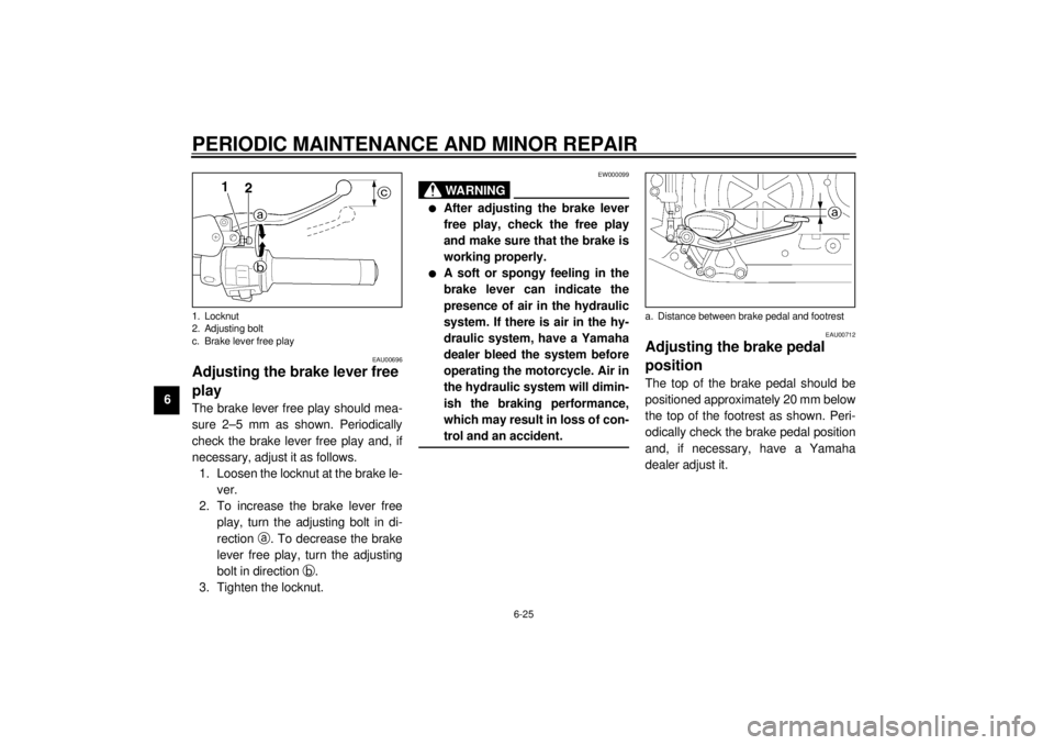
Adjusting the brake lever free
play The brake lever free play should mea-
sure 2–5 mm as shown. Periodically
check the brake lever free play and, if
necessary, adjust it as follows.
1. Loosen the locknut at the brake le-
ver.
2. To increase the brake lever free
play, turn the adjusting bolt in di-
rection
a. To decrease the brake
lever free play, turn the adjusting
bolt in direction
b.
3. Tighten the locknut.
EW000099
WARNING
@ l
After adjusting the brake lever
free play, check the free play
and make sure that the brake is
working properly.
l
A soft or spongy feeling in the
brake lever can indicate the
presence of air in the hydraulic
system. If there is air in the hy-
draulic system, have a Yamaha
dealer bleed the system before
operating the motorcycle. Air in
the hydraulic system will dimin-
ish the braking performance,
which may result in loss of con-
trol and an accident.
@
EAU00712
Adjusting the brake pedal
position The top of the brake pedal should be
positioned approximately 20 mm below
the top of the footrest as shown. Peri-
odically check the brake pedal position
and, if necessary, have a Yamaha
dealer adjust it.
1. Locknut
2. Adjusting bolt
c. Brake lever free play
a. Distance between brake pedal and footrest
E_3lr.book Page 25 Wednesday, November 22, 2000 4:10 PM
Page 70 of 110
PERIODIC MAINTENANCE AND MINOR REPAIR
6-27
6
EAU03418
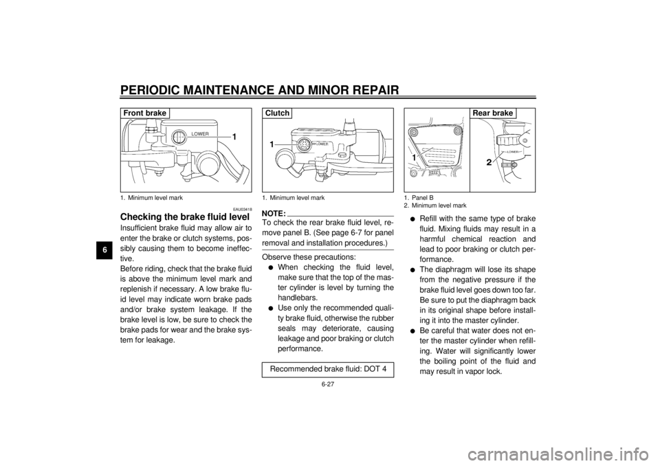
Checking the brake fluid level Insufficient brake fluid may allow air to
enter the brake or clutch systems, pos-
sibly causing them to become ineffec-
tive.
Before riding, check that the brake fluid
is above the minimum level mark and
replenish if necessary. A low brake flu-
id level may indicate worn brake pads
and/or brake system leakage. If the
brake level is low, be sure to check the
brake pads for wear and the brake sys-
tem for leakage.
NOTE:@ To check the rear brake fluid level, re-
move panel B. (See page 6-7 for panel
removal and installation procedures.) @Observe these precautions:l
When checking the fluid level,
make sure that the top of the mas-
ter cylinder is level by turning the
handlebars.
l
Use only the recommended quali-
ty brake fluid, otherwise the rubber
seals may deteriorate, causing
leakage and poor braking or clutch
performance.
l
Refill with the same type of brake
fluid. Mixing fluids may result in a
harmful chemical reaction and
lead to poor braking or clutch per-
formance.
l
The diaphragm will lose its shape
from the negative pressure if the
brake fluid level goes down too far.
Be sure to put the diaphragm back
in its original shape before install-
ing it into the master cylinder.
l
Be careful that water does not en-
ter the master cylinder when refill-
ing. Water will significantly lower
the boiling point of the fluid and
may result in vapor lock.
1. Minimum level markFront brake
1. Minimum level mark
Recommended brake fluid: DOT 4Clutch
1. Panel B
2. Minimum level mark
Rear brake
E_3lr.book Page 27 Wednesday, November 22, 2000 4:10 PM
Page 81 of 110
PERIODIC MAINTENANCE AND MINOR REPAIR
6-38
6
EAU03003
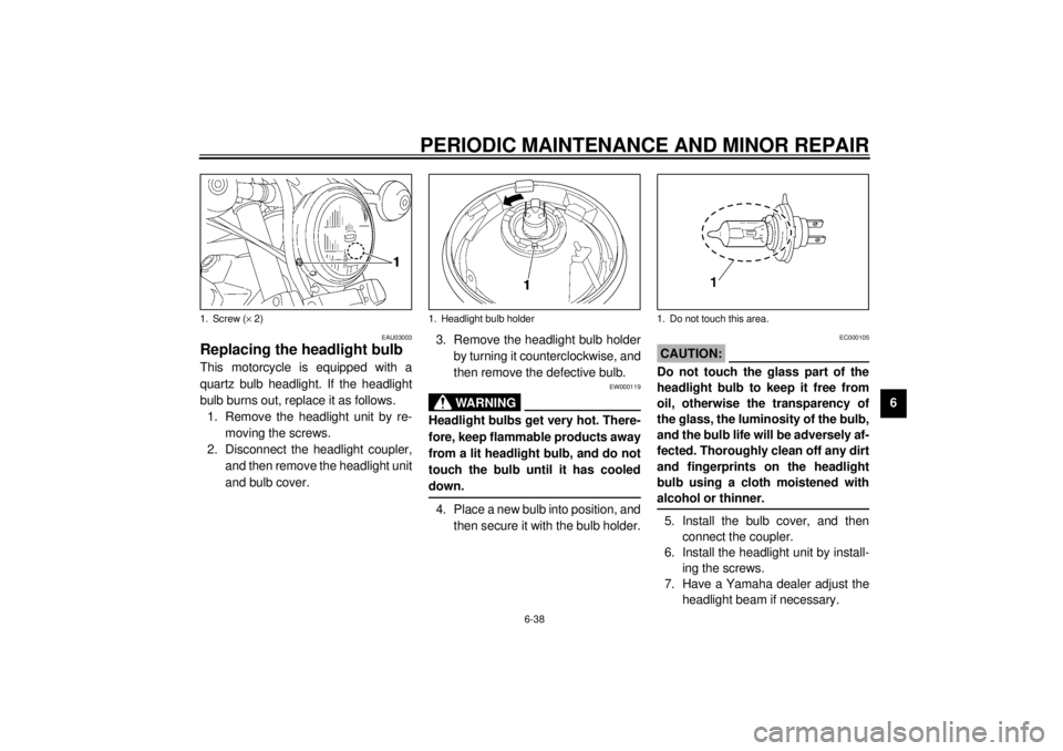
Replacing the headlight bulb This motorcycle is equipped with a
quartz bulb headlight. If the headlight
bulb burns out, replace it as follows.
1. Remove the headlight unit by re-
moving the screws.
2. Disconnect the headlight coupler,
and then remove the headlight unit
and bulb cover.3. Remove the headlight bulb holder
by turning it counterclockwise, and
then remove the defective bulb.
EW000119
WARNING
@ Headlight bulbs get very hot. There-
fore, keep flammable products away
from a lit headlight bulb, and do not
touch the bulb until it has cooled
down. @4. Place a new bulb into position, and
then secure it with the bulb holder.
EC000105
CAUTION:@ Do not touch the glass part of the
headlight bulb to keep it free from
oil, otherwise the transparency of
the glass, the luminosity of the bulb,
and the bulb life will be adversely af-
fected. Thoroughly clean off any dirt
and fingerprints on the headlight
bulb using a cloth moistened with
alcohol or thinner. @5. Install the bulb cover, and then
connect the coupler.
6. Install the headlight unit by install-
ing the screws.
7. Have a Yamaha dealer adjust the
headlight beam if necessary.
1. Screw (´ 2)
1. Headlight bulb holder
1. Do not touch this area.
E_3lr.book Page 38 Wednesday, November 22, 2000 4:10 PM