ECO mode YAMAHA VMAX 2012 Owners Manual
[x] Cancel search | Manufacturer: YAMAHA, Model Year: 2012, Model line: VMAX, Model: YAMAHA VMAX 2012Pages: 110, PDF Size: 3.09 MB
Page 10 of 110

SAFETY INFORMATION
1-3
1
●
Do not run engine in poorly venti-
lated or partially enclosed areas
such as barns, garages, or car-
ports.
●
Do not run engine outdoors where
engine exhaust can be drawn into
a building through openings such
as windows and doors.
Loading
Adding accessories or cargo to your
motorcycle can adversely affect stabili-
ty and handling if the weight distribution
of the motorcycle is changed. To avoid
the possibility of an accident, use ex-
treme caution when adding cargo or
accessories to your motorcycle. Use
extra care when riding a motorcycle
that has added cargo or accessories.
Here, along with the information about
accessories below, are some general
guidelines to follow if loading cargo to
your motorcycle:
The total weight of the operator, pas-
senger, accessories and cargo must
not exceed the maximum load limit.
Operation of an overloaded vehicle
could cause an accident. When loading within this weight limit,
keep the following in mind:
●
Cargo and accessory weight
should be kept as low and close to
the motorcycle as possible. Se-
curely pack your heaviest items as
close to the center of the vehicle as
possible and make sure to distrib-
ute the weight as evenly as possi-
ble on both sides of the motorcycle
to minimize imbalance or instabili-
ty.
●
Shifting weights can create a sud-
den imbalance. Make sure that ac-
cessories and cargo are securely
attached to the motorcycle before
riding. Check accessory mounts
and cargo restraints frequently.
Properly adjust the suspension for your load (suspension-ad-
justable models only), and
check the condition and pres-
sure of your tires.
Never attach any large or heavy items to the handlebar, front
fork, or front fender. These items, including such cargo as
sleeping bags, duffel bags, or
tents, can create unstable han-
dling or a slow steering re-
sponse.
●
This vehicle is not designed to
pull a trailer or to be attached to
a sidecar.
Genuine Yamaha Accessories
Choosing accessories for your vehicle
is an important decision. Genuine
Yamaha accessories, which are avail- able only from a Yamaha dealer, have
been designed, tested, and approved
by Yamaha for use on your vehicle.
Many companies with no connection to
Yamaha manufacture parts and acces- sories or offer other modifications for
Yamaha vehicles. Yamaha is not in a position to test the products that these
aftermarket companies produce.
Therefore, Yamaha can neither en-
dorse nor recommend the use of ac-
cessories not sold by Yamaha or
modifications not specifically recom-
mended by Yamaha, even if sold and
installed by a Yamaha dealer.
Maximum load: 190 kg (419 lb)
U2S3E3E0.book Page 3 Monday, September 19, 2011 8:42 AM
Page 20 of 110
INSTRUMENT AND CONTROL FUNCTIONS
3-5
3
●
This model is also equipped with a
self-diagnosis device for the oil
level detection circuit. If a problem
is detected in the oil level detection
circuit, the following cycle will be
repeated until the malfunction is
corrected: The oil level warning
light will flash ten times, then go off
for 2.5 seconds. If this occurs,
have a Yamaha dealer check the
vehicle.
EAU48700
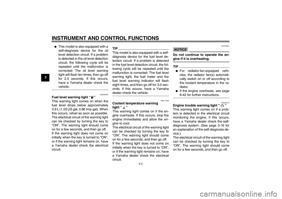
Fuel level warning light “ ”
This warning light comes on when the
fuel level drops below approximately
3.9 L (1.03 US gal, 0.86 Imp.gal). When
this occurs, refuel as soon as possible.
The electrical circuit of the warning light
can be checked by turning the key to
“ON”. The warning light should come
on for a few seconds, and then go off.
If the warning light does not come on
initially when the key is turned to “ON”,
or if the warning light remains on, have
a Yamaha dealer check the electrical
circuit.
TIPThis model is also equipped with a self-
diagnosis device for the fuel level de-
tection circuit. If a problem is detected
in the fuel level detection circuit, the fol-
lowing cycle will be repeated until the
malfunction is corrected: The fuel level
warning light, the fuel meter and the
fuel level warning indicator will flash
eight times, and then go off for 3.0 sec-
onds. If this occurs, have a Yamaha
dealer check the vehicle.
EAU11446
Coolant temperature warning
light “ ”
This warning light comes on if the en-
gine overheats. If this occurs, stop the
engine immediately and allow the en-
gine to cool.
The electrical circuit of the warning light
can be checked by turning the key to
“ON”. The warning light should come
on for a few seconds, and then go off.
If the warning light does not come on
initially when the key is turned to “ON”,
or if the warning light remains on, have
a Yamaha dealer check the electrical
circuit.
NOTICE
ECA10021
Do not continue to operate the en-
gine if it is overheating.TIP●
For radiator-fan-equipped vehi-
cles, the radiator fan(s) automati-
cally switch on or off according to
the coolant temperature in the ra-
diator.
●
If the engine overheats, see page
6-42 for further instructions.
EAU42774
Engine trouble warning light “ ”
This warning light comes on if a prob-
lem is detected in the electrical circuit
monitoring the engine. If this occurs,
have a Yamaha dealer check the self-
diagnosis system. (See page 3-16 for
an explanation of the self-diagnosis de-
vice.)
The electrical circuit of the warning light
can be checked by turning the key to
“ON”. The warning light should come
on for a few seconds, and then go off.
U2S3E3E0.book Page 5 Monday, September 19, 2011 8:42 AM
Page 25 of 110
INSTRUMENT AND CONTROL FUNCTIONS
3-10
3
coolant temperature warning indicator
flash, stop the vehicle and let the en-
gine cool. (See page 6-42.)
NOTICE
ECA10021
Do not continue to operate the en-
gine if it is overheating.Select mode
The various functions of this multi-func-
tion display are adjusted in the Select
mode.TIP●
The transmission must be in neu-
tral to change settings in this
mode.
●
Shifting the transmission into gear
saves all settings made, then can-
cels the Select mode and displays
the Normal mode in all screens.
●
Depending on the screen, pushing
“RESET” saves settings or can-
cels the Select mode to display the
Normal mode.
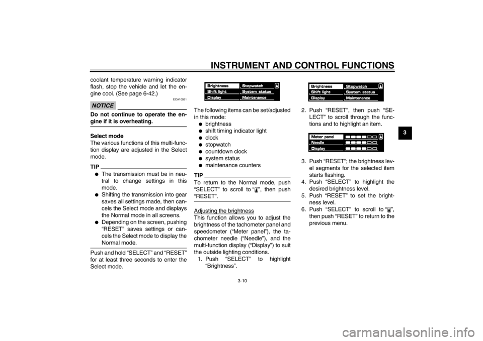
Push and hold “SELECT” and “RESET”
for at least three seconds to enter the
Select mode. The following items can be set/adjusted
in this mode:
●
brightness
●
shift timing indicator light
●
clock
●
stopwatch
●
countdown clock
●
system status
●
maintenance counters
TIPTo return to the Normal mode, push
“SELECT” to scroll to “ ”, then push
“RESET”.Adjusting the brightnessThis function allows you to adjust the
brightness of the tachometer panel and
speedometer (“Meter panel”), the ta-
chometer needle (“Needle”), and the
multi-function display (“Display”) to suit
the outside lighting conditions.
1. Push “SELECT” to highlight “Brightness”. 2. Push “RESET”, then push “SE-
LECT” to scroll through the func-
tions and to highlight an item.
3. Push “RESET”; the brightness lev- el segments for the selected item
starts flashing.
4. Push “SELECT” to highlight the desired brightness level.
5. Push “RESET” to set the bright- ness level.
6. Push “SELECT” to scroll to “ ”, then push “RESET” to return to the
previous menu.
U2S3E3E0.book Page 10 Monday, September 19, 2011 8:42 AM
Page 28 of 110
INSTRUMENT AND CONTROL FUNCTIONS
3-13
33. Push “SELECT” to highlight the
desired brightness level.
4. Push “RESET” to set the selected brightness level.
5. Push “RESET” to return to the pre- vious menu.
6. Push “SELECT” to scroll to “ ”, then push “RESET”. This allows
you to select another item in the
menu.
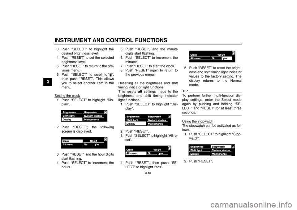
Setting the clock
1. Push “SELECT” to highlight “Dis- play”.
2. Push “RESET”; the following screen is displayed.
3. Push “RESET” and the hour digits start flashing.
4. Push “SELECT” to increment the hours. 5. Push “RESET”, and the minute
digits start flashing.
6. Push “SELECT” to increment the minutes.
7. Push “RESET” to start the clock.
8. Push “RESET” again to return to the previous menu.
Resetting all the brightness and shift
timing indicator light functionsThis resets all settings made to the
brightness and shift timing indicator
light functions. 1. Push “SELECT” to highlight “Dis- play”.
2. Push “RESET”.
3. Push “SELECT” to highlight “All re- set”.
4. Push “RESET”, then push “SE- LECT” to highlight “Yes”. 5. Push “RESET” to reset the bright-
ness and shift timing light indicator
values to the factory setting. The
display returns to the Normal
mode.
TIPTo perform further multi-function dis-
play settings, enter the Select mode
again by pushing and holding “SE-
LECT” and “RESET” for at least three
seconds.Using the stopwatchThe stopwatch can be activated as fol-
lows.1. Push “SELECT” to highlight “Stop- watch”.
2. Push “RESET”.
U2S3E3E0.book Page 13 Monday, September 19, 2011 8:42 AM
Page 29 of 110
INSTRUMENT AND CONTROL FUNCTIONS
3-14
3
3. Push “SELECT” to highlight “Stop-
watch”.
4. Push “RESET”. The multi-function display chang-
es to the Normal mode and the
stopwatch is displayed in place of
the clock.
5. Push “SELECT” to start the stop- watch.
6. Push the start switch “ ” or “SE- LECT” to stop the stopwatch.
7. Push “RESET” to reset the stop- watch.
TIP●
If neither “SELECT” nor “RESET”
are pushed for one minute, the
screen automatically changes to
the Normal mode.
●
Pushing “RESET” for at least two
seconds changes the screen to
the Normal mode.
●
To perform further multi-function
display settings, enter the Select
mode again by pushing and hold-
ing “SELECT” and “RESET” for at
least three seconds.
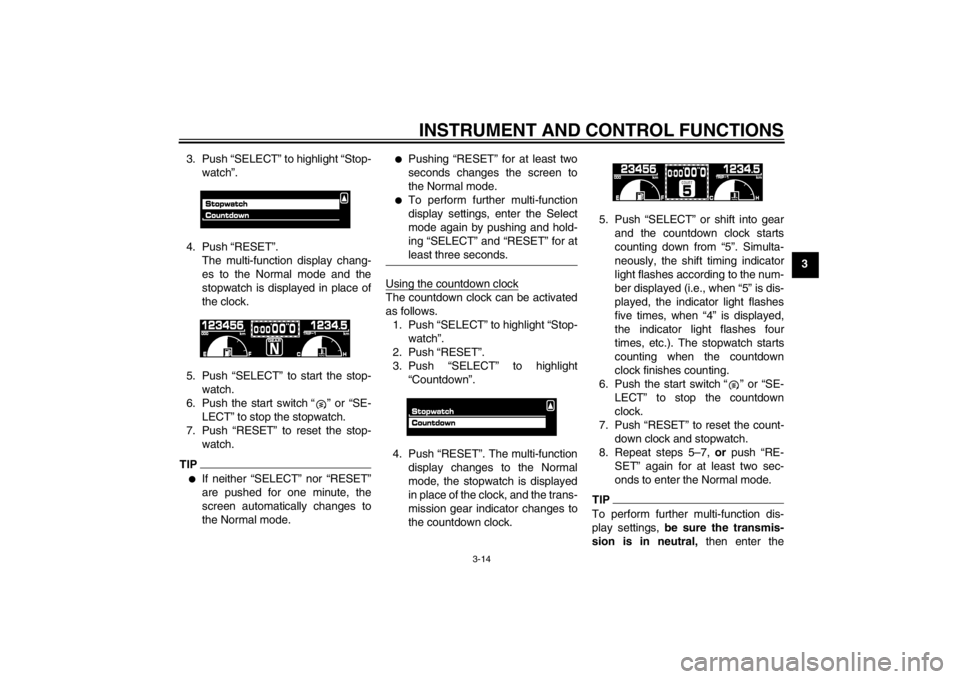
Using the countdown clockThe countdown clock can be activated
as follows.1. Push “SELECT” to highlight “Stop- watch”.
2. Push “RESET”.
3. Push “SELECT” to highlight “Countdown”.
4. Push “RESET”. The multi-function display changes to the Normal
mode, the stopwatch is displayed
in place of the clock, and the trans-
mission gear indicator changes to
the countdown clock. 5. Push “SELECT” or shift into gear
and the countdown clock starts
counting down from “5”. Simulta-
neously, the shift timing indicator
light flashes according to the num-
ber displayed (i.e., when “5” is dis-
played, the indicator light flashes
five times, when “4” is displayed,
the indicator light flashes four
times, etc.). The stopwatch starts
counting when the countdown
clock finishes counting.
6. Push the start switch “ ” or “SE- LECT” to stop the countdown
clock.
7. Push “RESET” to reset the count- down clock and stopwatch.
8. Repeat steps 5–7, or push “RE-
SET” again for at least two sec-
onds to enter the Normal mode.
TIPTo perform further multi-function dis-
play settings, be sure the transmis-
sion is in neutral, then enter the
U2S3E3E0.book Page 14 Monday, September 19, 2011 8:42 AM
Page 30 of 110
INSTRUMENT AND CONTROL FUNCTIONS
3-15
3Select mode again by pushing and
holding “SELECT” and “RESET” for at
least three seconds.
Checking and resetting the system sta-tusThe status/readings of the following
items are displayed, and the tripmeters
can be reset.●
tripmeters and odometer
●
fuel consumption
●
air intake temperature
●
throttle opening position
TIP●
The “System status” menu cannot
be entered if the fuel level warning
light or coolant temperature warn-
ing light is on.
●
If, when the engine is running
while the system status menu is
displayed, the fuel level warning
light or coolant temperature warn-
ing light comes on, the Normal
mode is automatically displayed.
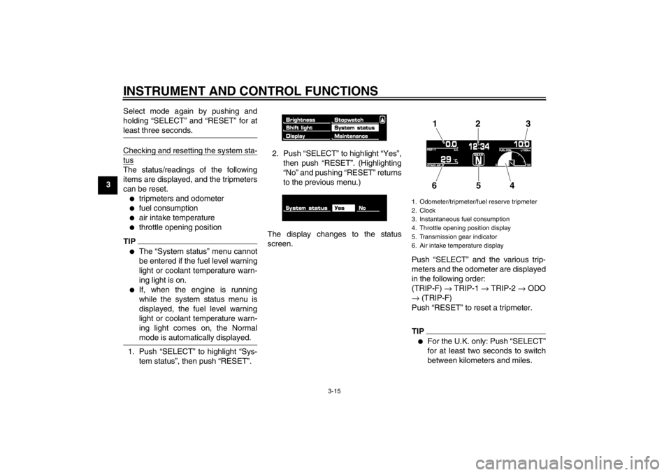
1. Push “SELECT” to highlight “Sys-
tem status”, then push “RESET”. 2. Push “SELECT” to highlight “Yes”,
then push “RESET”. (Highlighting
“No” and pushing “RESET” returns
to the previous menu.)
The display changes to the status
screen. Push “SELECT” and the various trip-
meters and the odometer are displayed
in the following order:
(TRIP-F) → TRIP-1 → TRIP-2 → ODO
→ (TRIP-F)
Push “RESET” to reset a tripmeter.
TIP●
For the U.K. only: Push “SELECT”
for at least two seconds to switch
between kilometers and miles.
1. Odometer/tripmeter/fuel reserve tripmeter
2. Clock
3. Instantaneous fuel consumption
4. Throttle opening position display
5. Transmission gear indicator
6. Air intake temperature display
12 3
654
U2S3E3E0.book Page 15 Monday, September 19, 2011 8:42 AM
Page 31 of 110
INSTRUMENT AND CONTROL FUNCTIONS
3-16
3
●
Pushing “RESET” displays the
Normal mode for five seconds.
Pushing “SELECT” and “RESET”
for at least three seconds, chang-
es the display to the Normal mode.
●
To perform further multi-function
display settings, enter the Select
mode again by pushing and hold-
ing “SELECT” and “RESET” for at
least three seconds.
Resetting the maintenance countersThis function allows you to reset the
maintenance counters for the tires, the
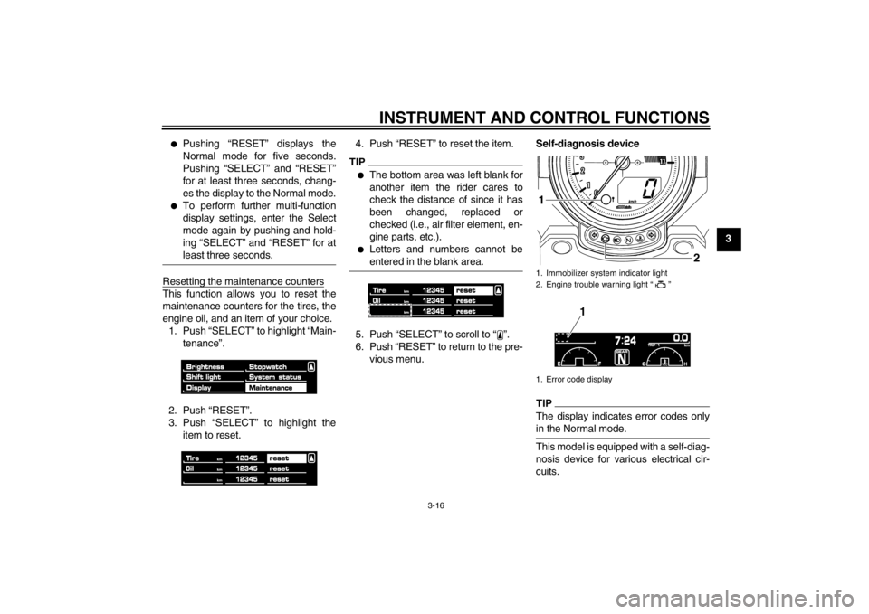
engine oil, and an item of your choice.1. Push “SELECT” to highlight “Main- tenance”.
2. Push “RESET”.
3. Push “SELECT” to highlight the item to reset. 4. Push “RESET” to reset the item.
TIP●
The bottom area was left blank for
another item the rider cares to
check the distance of since it has
been changed, replaced or
checked (i.e., air filter element, en-
gine parts, etc.).
●
Letters and numbers cannot be
entered in the blank area.
5. Push “SELECT” to scroll to “ ”.
6. Push “RESET” to return to the pre-
vious menu. Self-diagnosis device
TIPThe display indicates error codes only
in the Normal mode.This model is equipped with a self-diag-
nosis device for various electrical cir-
cuits.1. Immobilizer system indicator light
2. Engine trouble warning light “ ”
1. Error code display
2
1
1
U2S3E3E0.book Page 16 Monday, September 19, 2011 8:42 AM
Page 52 of 110
OPERATION AND IMPORTANT RIDING POINTS
5-1
5
EAU15951
Read the Owner’s Manual carefully to
become familiar with all controls. If
there is a control or function you do not
understand, ask your Yamaha dealer.
WARNING
EWA10271
Failure to familiarize yourself with
the controls can lead to loss of con-
trol, which could cause an accident
or injury.
EAU48710
TIPThis model is equipped with:●
a lean angle sensor to stop the en-
gine in case of a turnover. In this
case, the multi-function display in-
dicates error code 30, but this is
not a malfunction. Turn the key to
“OFF” and then to “ON” to clear the
error code. Failing to do so will pre-
vent the engine from starting even
though the engine will crank when
pushing the start switch.
●
an engine auto-stop system. The
engine stops automatically if left
idling for 20 minutes. If the engine
stops, simply push the start switch
to restart the engine.
EAU51690
Starting the engine In order for the ignition circuit cut-off
system to enable starting, one of the
following conditions must be met:●
The transmission is in the neutral
position.
●
The transmission is in gear with
the clutch lever pulled and the
sidestand up.
See page 3-32 for more informa-
tion.
1. Turn the key to “ON” and make sure that the engine stop switch is
set to “ ”.
The following warning lights and
indicator lights should come on for
a few seconds, then go off.●
Oil level warning light
●
Fuel level warning light
●
Coolant temperature warning
light
●
Engine trouble warning light
●
Shift timing indicator light
●
Immobilizer system indicator
light
U2S3E3E0.book Page 1 Monday, September 19, 2011 8:42 AM
Page 78 of 110

PERIODIC MAINTENANCE AND ADJUSTMENT
6-23
6
EAU21962
Cast wheels To maximize the performance, durabil-
ity, and safe operation of your vehicle,
note the following points regarding the
specified wheels.●
The wheel rims should be checked
for cracks, bends, warpage or oth-
er damage before each ride. If any
damage is found, have a Yamaha
dealer replace the wheel. Do not
attempt even the smallest repair to
the wheel. A deformed or cracked
wheel must be replaced.
●
The wheel should be balanced
whenever either the tire or wheel
has been changed or replaced. An
unbalanced wheel can result in
poor performance, adverse han-
dling characteristics, and a short-
ened tire life.
EAU42850
Clutch lever Since this model is equipped with a hy-
draulic clutch, adjusting the clutch lever
free play is not needed. However, it is
necessary to check the hydraulic sys-
tem for leakage before each ride. If the
clutch lever free play does become ex-
cessive, and shifting becomes rough or
clutch slippage occurs, causing poor
acceleration, there may be air in the
clutch system. If there is air in the hy-
draulic system, have a Yamaha dealer
bleed the system before operating the
motorcycle.
EAU37913
Checking the brake lever free
play There should be no free play at the
brake lever end. If there is free play,
have a Yamaha dealer inspect the
brake system.
WARNING
EWA14211
A soft or spongy feeling in the brake
lever can indicate the presence of air
in the hydraulic system. If there is air
in the hydraulic system, have a
Yamaha dealer bleed the system be- fore operating the vehicle. Air in the
hydraulic system will diminish the1. No brake lever free play
1
U2S3E3E0.book Page 23 Monday, September 19, 2011 8:42 AM
Page 103 of 110

SPECIFICATIONS
8-1
8
Dimensions:Overall length:2395 mm (94.3 in)
Overall width:
820 mm (32.3 in)
Overall height: 1190 mm (46.9 in)
Seat height: 775 mm (30.5 in)
Wheelbase:
1700 mm (66.9 in)
Ground clearance: 140 mm (5.51 in)
Minimum turning radius: 3500 mm (137.8 in)Weight:Curb weight:310 kg (683 lb)Engine:Engine type:
Liquid cooled 4-stroke, DOHC
Cylinder arrangement: V-type 4-cylinder
Displacement: 1679 cm³
Bore × stroke:
90.0 × 66.0 mm (3.54 × 2.60 in)
Compression ratio: 11.30 : 1
Starting system: Electric starter
Lubrication system:
Wet sump
Engine oil:Recommended brand:YAMALUBE
Type:
SAE 10W-30, 10W-40, 10W-50, 15W-40,
20W-40 or 20W-50
Recommended engine oil grade: API service SG type or higher, JASO
standard MA
Engine oil quantity:
Without oil filter cartridge replacement:4.30 L (4.55 US qt, 3.78 Imp.qt)
With oil filter cartridge replacement:
4.70 L (4.97 US qt, 4.14 Imp.qt)Final gear oil:Type:Yamaha genuine shaft drive gear oil SAE 80 API GL-5
Quantity: 0.30 L (0.32 US qt, 0.26 Imp.qt)
Cooling system:Coolant reservoir capacity (up to the
maximum level mark):0.27 L (0.29 US qt, 0.24 Imp.qt)
Radiator capacity (including all routes): 3.75 L (3.96 US qt, 3.30 Imp.qt)Air filter:Air filter element:Oil-coated paper elementFuel:Recommended fuel:
Premium unleaded gasoline only
Fuel tank capacity: 15.0 L (3.96 US gal, 3.30 Imp.gal)
Fuel reserve amount: 3.9 L (1.03 US gal, 0.86 Imp.gal)Fuel injection:Throttle body:ID mark:
2S31 00Spark plug(s):Manufacturer/model: NGK/CR9EIA
Manufacturer/model:
DENSO/IU27D
Spark plug gap: 0.8–0.9 mm (0.031–0.035 in)Clutch:Clutch type:
Wet, multiple-discTransmission:Primary reduction ratio:1.509 (86/57)
–20 –10 0 1020 30 40 50 �C
10 30 50 70 90 110
0 130 �F
SAE 10W-30
SAE 15W-40SAE 20W-40SAE 20W-50
SAE 10W-40SAE 10W-50
U2S3E3E0.book Page 1 Monday, September 19, 2011 8:42 AM