engine overheat YAMAHA VX 2009 Owners Manual
[x] Cancel search | Manufacturer: YAMAHA, Model Year: 2009, Model line: VX, Model: YAMAHA VX 2009Pages: 92, PDF Size: 6.67 MB
Page 38 of 92
Features and functions
31
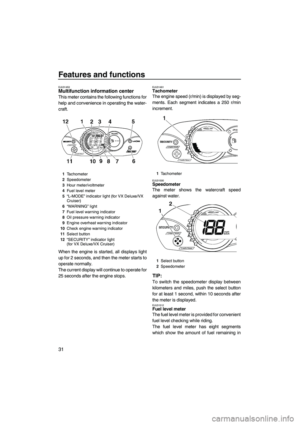
EJU31453Multifunction information center
This meter contains the following functions for
help and convenience in operating the water-
craft.
When the engine is started, all displays light
up for 2 seconds, and then the meter starts to
operate normally.
The current display will continue to operate for
25 seconds after the engine stops.
EJU31461Tachometer
The engine speed (r/min) is displayed by seg-
ments. Each segment indicates a 250 r/min
increment.
EJU31500Speedometer
The meter shows the watercraft speed
against water.
TIP:
To switch the speedometer display between
kilometers and miles, push the select button
for at least 1 second, within 10 seconds after
the meter is displayed.
EJU31512Fuel level meter
The fuel level meter is provided for convenient
fuel level checking while riding.
The fuel level meter has eight segments
which show the amount of fuel remaining in
1Tachometer
2Speedometer
3Hour meter/voltmeter
4Fuel level meter
5“L-MODE” indicator light (for VX Deluxe/VX
Cruiser)
6“WARNING” light
7Fuel level warning indicator
8Oil pressure warning indicator
9Engine overheat warning indicator
10Check engine warning indicator
11Select button
12“SECURITY” indicator light
(for VX Deluxe/VX Cruiser)1Tachometer
1Select button
2Speedometer
UF2L70E0.book Page 31 Thursday, June 19, 2008 8:38 AM
Page 40 of 92
Features and functions
33
TIP:
Press the select button on the multifunction
information center to stop the buzzer.
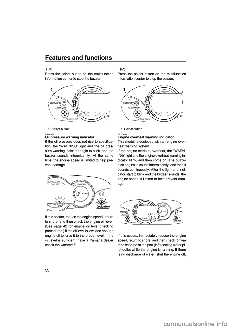
EJU31622Oil pressure warning indicator
If the oil pressure does not rise to specifica-
tion, the “WARNING” light and the oil pres-
sure warning indicator begin to blink, and the
buzzer sounds intermittently. At the same
time, the engine speed is limited to help pre-
vent damage.
If this occurs, reduce the engine speed, return
to shore, and then check the engine oil level.
(See page 42 for engine oil level checking
procedures.) If the oil level is low, add enough
engine oil to raise it to the proper level. If the
oil level is sufficient, have a Yamaha dealer
check the watercraft.
TIP:
Press the select button on the multifunction
information center to stop the buzzer.
EJU31605Engine overheat warning indicator
This model is equipped with an engine over-
heat warning system.
If the engine starts to overheat, the “WARN-
ING” light and the engine overheat warning in-
dicator blink, and then come on. The buzzer
also begins to sound intermittently, and then it
sounds continuously. After the light and indi-
cator start to blink and the buzzer sounds, the
engine speed is limited to help prevent dam-
age.
If this occurs, immediately reduce the engine
speed, return to shore, and then check for wa-
ter discharge at the port (left) cooling water pi-
lot outlet while the engine is running. If there
is no discharge of water, shut the engine off,
1Select button1Select button
UF2L70E0.book Page 33 Thursday, June 19, 2008 8:38 AM
Page 41 of 92
Features and functions
34
and then check the intake grate and impeller
for clogging. (See page 78 for more informa-
tion.) NOTICE: If you cannot locate and
correct the cause of the overheating, con-
sult a Yamaha dealer. Continuing to oper-
ate at higher speeds could result in severe
engine damage.
[ECJ00041]
TIP:
Press the select button on the multifunction
information center to stop the buzzer.
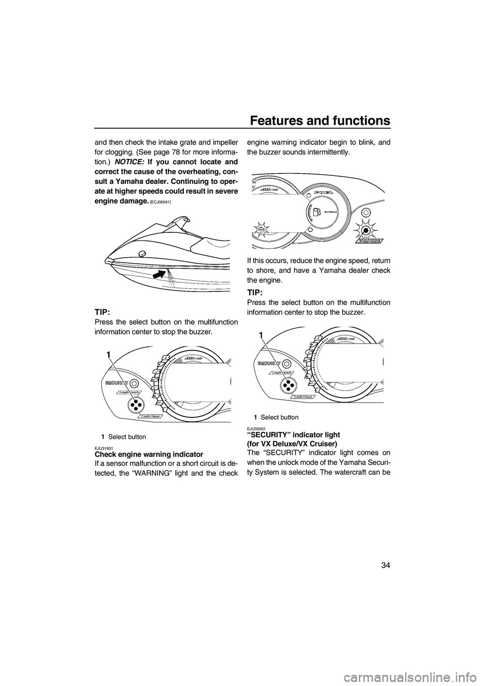
EJU31631Check engine warning indicator
If a sensor malfunction or a short circuit is de-
tected, the “WARNING” light and the checkengine warning indicator begin to blink, and
the buzzer sounds intermittently.
If this occurs, reduce the engine speed, return
to shore, and have a Yamaha dealer check
the engine.
TIP:
Press the select button on the multifunction
information center to stop the buzzer.
EJU35001“SECURITY” indicator light
(for VX Deluxe/VX Cruiser)
The “SECURITY” indicator light comes on
when the unlock mode of the Yamaha Securi-
ty System is selected. The watercraft can be1Select button
1Select button
UF2L70E0.book Page 34 Thursday, June 19, 2008 8:38 AM
Page 53 of 92
Operation
46
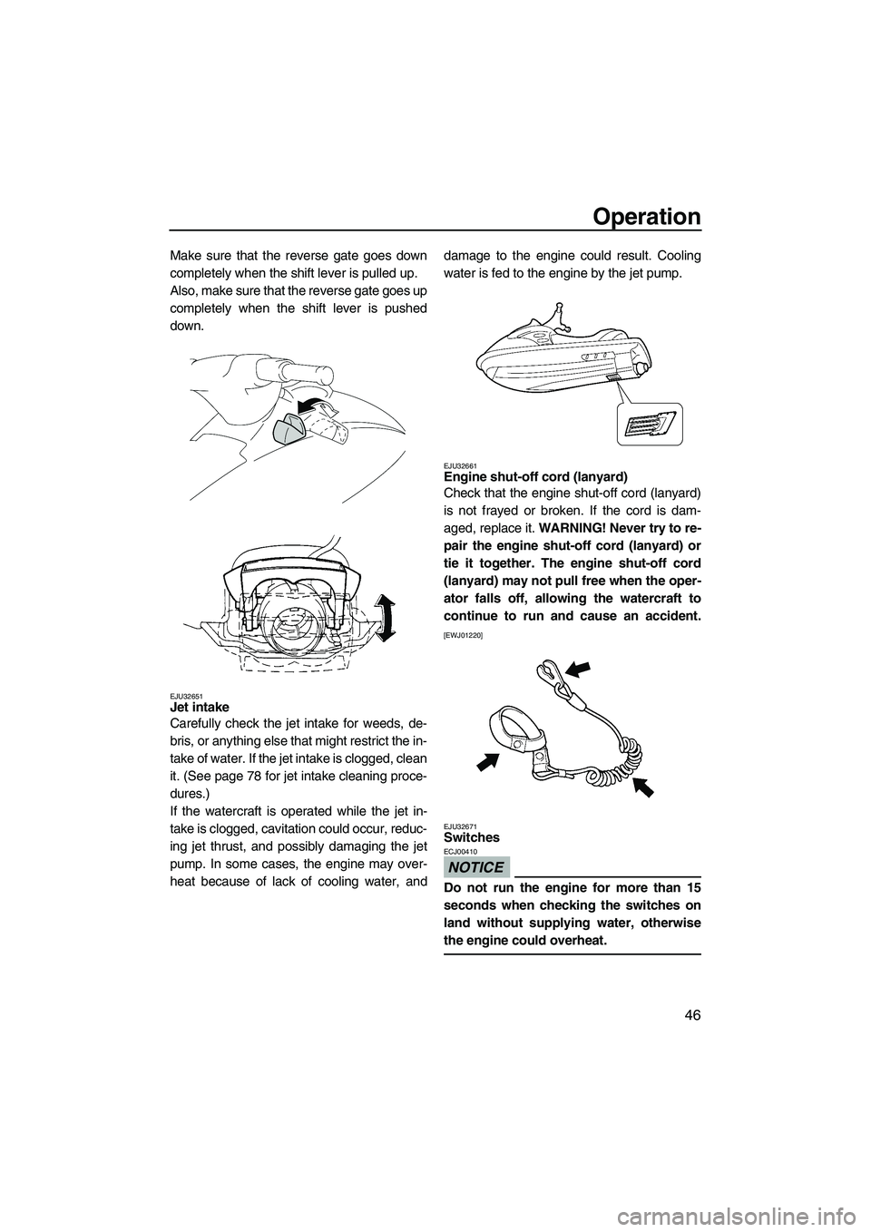
Make sure that the reverse gate goes down
completely when the shift lever is pulled up.
Also, make sure that the reverse gate goes up
completely when the shift lever is pushed
down.
EJU32651Jet intake
Carefully check the jet intake for weeds, de-
bris, or anything else that might restrict the in-
take of water. If the jet intake is clogged, clean
it. (See page 78 for jet intake cleaning proce-
dures.)
If the watercraft is operated while the jet in-
take is clogged, cavitation could occur, reduc-
ing jet thrust, and possibly damaging the jet
pump. In some cases, the engine may over-
heat because of lack of cooling water, anddamage to the engine could result. Cooling
water is fed to the engine by the jet pump.
EJU32661Engine shut-off cord (lanyard)
Check that the engine shut-off cord (lanyard)
is not frayed or broken. If the cord is dam-
aged, replace it. WARNING! Never try to re-
pair the engine shut-off cord (lanyard) or
tie it together. The engine shut-off cord
(lanyard) may not pull free when the oper-
ator falls off, allowing the watercraft to
continue to run and cause an accident.
[EWJ01220]
EJU32671
Switches
NOTICE
ECJ00410
Do not run the engine for more than 15
seconds when checking the switches on
land without supplying water, otherwise
the engine could overheat.
UF2L70E0.book Page 46 Thursday, June 19, 2008 8:38 AM
Page 56 of 92
Operation
49
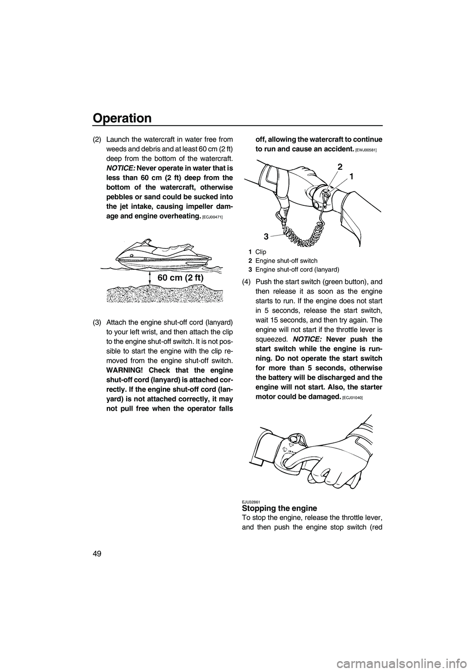
(2) Launch the watercraft in water free from
weeds and debris and at least 60 cm (2 ft)
deep from the bottom of the watercraft.
NOTICE: Never operate in water that is
less than 60 cm (2 ft) deep from the
bottom of the watercraft, otherwise
pebbles or sand could be sucked into
the jet intake, causing impeller dam-
age and engine overheating.
[ECJ00471]
(3) Attach the engine shut-off cord (lanyard)
to your left wrist, and then attach the clip
to the engine shut-off switch. It is not pos-
sible to start the engine with the clip re-
moved from the engine shut-off switch.
WARNING! Check that the engine
shut-off cord (lanyard) is attached cor-
rectly. If the engine shut-off cord (lan-
yard) is not attached correctly, it may
not pull free when the operator fallsoff, allowing the watercraft to continue
to run and cause an accident.
[EWJ00581]
(4) Push the start switch (green button), and
then release it as soon as the engine
starts to run. If the engine does not start
in 5 seconds, release the start switch,
wait 15 seconds, and then try again. The
engine will not start if the throttle lever is
squeezed. NOTICE: Never push the
start switch while the engine is run-
ning. Do not operate the start switch
for more than 5 seconds, otherwise
the battery will be discharged and the
engine will not start. Also, the starter
motor could be damaged.
[ECJ01040]
EJU32861
Stopping the engine
To stop the engine, release the throttle lever,
and then push the engine stop switch (red
1Clip
2Engine shut-off switch
3Engine shut-off cord (lanyard)
UF2L70E0.book Page 49 Thursday, June 19, 2008 8:38 AM
Page 60 of 92
Operation
53
throttle lever when trying to steer away
from objects—you need throttle to steer.
EJU33092Boarding and starting in shallow water
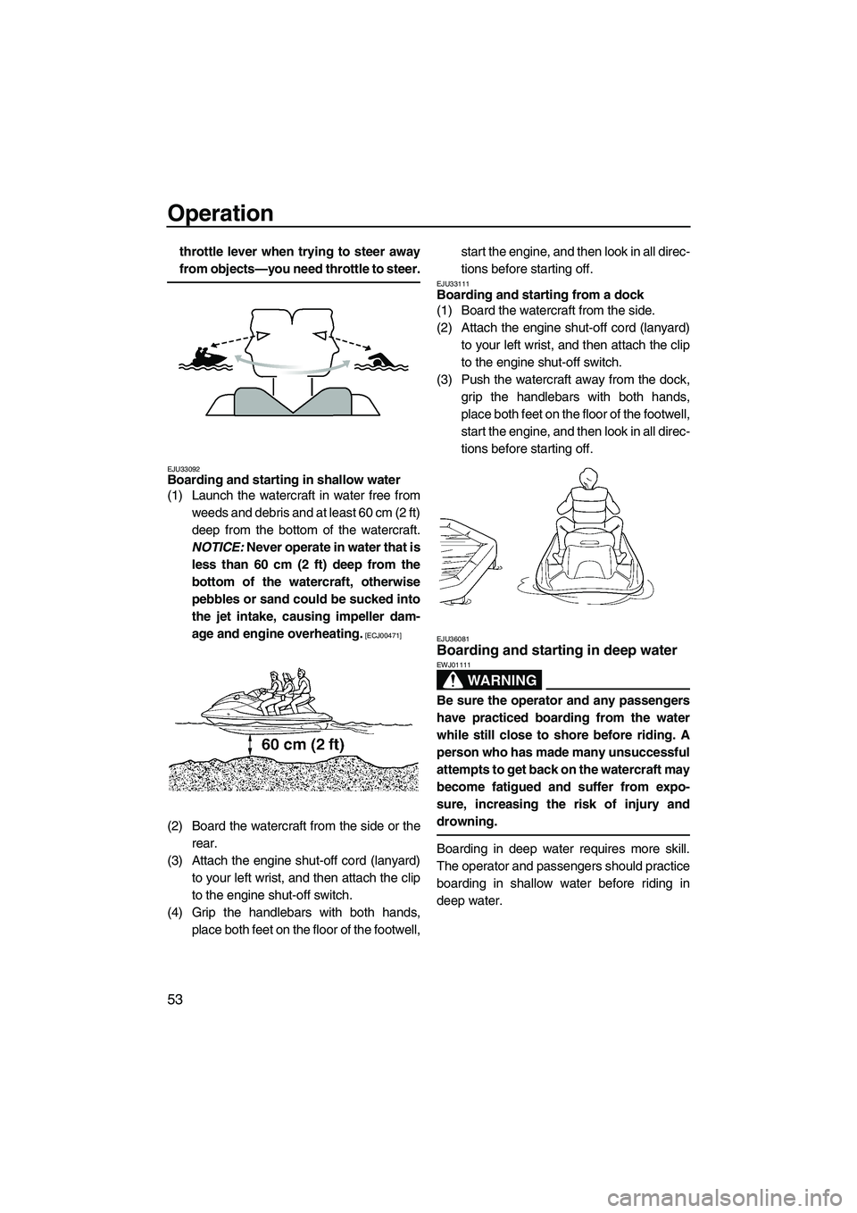
(1) Launch the watercraft in water free from
weeds and debris and at least 60 cm (2 ft)
deep from the bottom of the watercraft.
NOTICE: Never operate in water that is
less than 60 cm (2 ft) deep from the
bottom of the watercraft, otherwise
pebbles or sand could be sucked into
the jet intake, causing impeller dam-
age and engine overheating.
[ECJ00471]
(2) Board the watercraft from the side or the
rear.
(3) Attach the engine shut-off cord (lanyard)
to your left wrist, and then attach the clip
to the engine shut-off switch.
(4) Grip the handlebars with both hands,
place both feet on the floor of the footwell,start the engine, and then look in all direc-
tions before starting off.
EJU33111Boarding and starting from a dock
(1) Board the watercraft from the side.
(2) Attach the engine shut-off cord (lanyard)
to your left wrist, and then attach the clip
to the engine shut-off switch.
(3) Push the watercraft away from the dock,
grip the handlebars with both hands,
place both feet on the floor of the footwell,
start the engine, and then look in all direc-
tions before starting off.
EJU36081Boarding and starting in deep water
WARNING
EWJ01111
Be sure the operator and any passengers
have practiced boarding from the water
while still close to shore before riding. A
person who has made many unsuccessful
attempts to get back on the watercraft may
become fatigued and suffer from expo-
sure, increasing the risk of injury and
drowning.
Boarding in deep water requires more skill.
The operator and passengers should practice
boarding in shallow water before riding in
deep water.
UF2L70E0.book Page 53 Thursday, June 19, 2008 8:38 AM
Page 69 of 92
Maintenance and care
62
EJU33490
Storage
WARNING
EWJ00330
Always place the watercraft upright in a
horizontal position when storing it, other-
wise fuel could leak out into the engine or
engine compartment, which could create a
fire hazard.
Storage for long periods of time, such as win-
ter storage, requires preventive maintenance
to ensure against deterioration. It is advisable
to have the watercraft serviced by a Yamaha
dealer prior to storage. However, the following
procedures can be performed by the owner.
EJU33544Flushing the cooling system
Flushing the cooling system is essential to
prevent it from clogging with salt, sand, or dirt.
(1) Place the watercraft in a horizontal posi-
tion.
(2) Remove the seat. (See page 23 for seat
removal and installation procedures.)
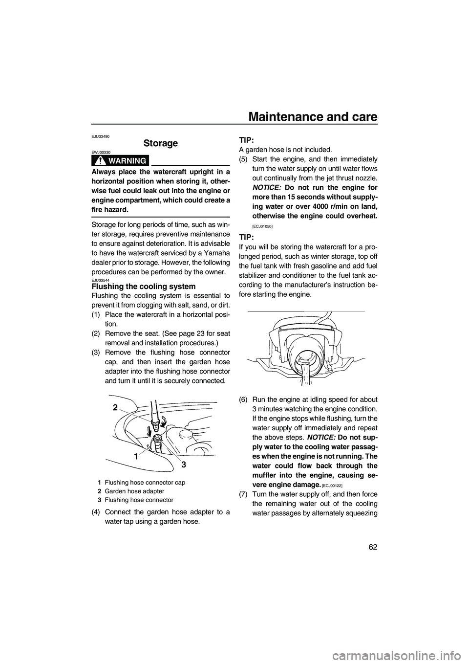
(3) Remove the flushing hose connector
cap, and then insert the garden hose
adapter into the flushing hose connector
and turn it until it is securely connected.
(4) Connect the garden hose adapter to a
water tap using a garden hose.
TIP:
A garden hose is not included.
(5) Start the engine, and then immediately
turn the water supply on until water flows
out continually from the jet thrust nozzle.
NOTICE: Do not run the engine for
more than 15 seconds without supply-
ing water or over 4000 r/min on land,
otherwise the engine could overheat.
[ECJ01050]
TIP:
If you will be storing the watercraft for a pro-
longed period, such as winter storage, top off
the fuel tank with fresh gasoline and add fuel
stabilizer and conditioner to the fuel tank ac-
cording to the manufacturer’s instruction be-
fore starting the engine.
(6) Run the engine at idling speed for about
3 minutes watching the engine condition.
If the engine stops while flushing, turn the
water supply off immediately and repeat
the above steps. NOTICE: Do not sup-
ply water to the cooling water passag-
es when the engine is not running. The
water could flow back through the
muffler into the engine, causing se-
vere engine damage.
[ECJ00122]
(7) Turn the water supply off, and then force
the remaining water out of the cooling
water passages by alternately squeezing
1Flushing hose connector cap
2Garden hose adapter
3Flushing hose connector
UF2L70E0.book Page 62 Friday, June 20, 2008 12:57 PM
Page 70 of 92
Maintenance and care
63
and releasing the throttle lever for 10 to
15 seconds.
(8) Stop the engine.
(9) Remove the garden hose adapter and in-
stall the flushing hose connector cap.
(10) Install the seat.
EJU33623Lubrication
(1) Remove the seat. (See page 23 for seat
removal and installation procedures.)
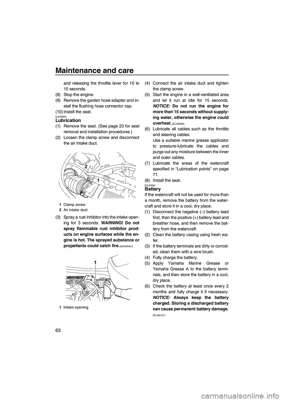
(2) Loosen the clamp screw and disconnect
the air intake duct.
(3) Spray a rust inhibitor into the intake open-
ing for 3 seconds. WARNING! Do not
spray flammable rust inhibitor prod-
ucts on engine surfaces while the en-
gine is hot. The sprayed substance or
propellants could catch fire.
[EWJ00261]
(4) Connect the air intake duct and tighten
the clamp screw.
(5) Start the engine in a well-ventilated area
and let it run at idle for 15 seconds.
NOTICE: Do not run the engine for
more than 15 seconds without supply-
ing water, otherwise the engine could
overheat.
[ECJ00562]
(6) Lubricate all cables such as the throttle
and steering cables.
Use a suitable marine grease applicator
to pressure-lubricate the cables and
purge out any moisture between the inner
and outer cables.
(7) Lubricate the areas of the watercraft
specified in “Lubrication points” on page
71.
(8) Install the seat.
EJU33681Battery
If the watercraft will not be used for more than
a month, remove the battery from the water-
craft and store it in a cool, dry place.
(1) Disconnect the negative (–) battery lead
first, then the positive (+) battery lead and
breather hose, and then remove the bat-
tery from the watercraft.
(2) Clean the battery casing using fresh wa-
ter.
(3) If the battery terminals are dirty or corrod-
ed, clean them with a wire brush.
(4) Fully charge the battery.
(5) Apply Yamaha Marine Grease or
Yamaha Grease A to the battery termi-
nals, and then store the battery in a cool,
dry place.
(6) Check the battery at least once every 2
months and fully charge it if necessary.
NOTICE: Always keep the battery
charged. Storing a discharged battery
can cause permanent battery damage.
[ECJ00101]
1Clamp screw
2Air intake duct
1Intake opening
UF2L70E0.book Page 63 Thursday, June 19, 2008 8:38 AM
Page 85 of 92
Trouble recovery
78
EJU34620
Emergency procedures EJU34631Cleaning the jet intake and impeller
WARNING
EWJ00780
Before attempting to remove weeds or de-
bris from the jet intake or impeller area,
shut the engine off and remove the clip
from the engine shut-off switch. Severe in-
jury or death could result from coming in
contact with the rotating parts of the jet
pump.
If weeds or debris gets caught in the jet intake
or impeller, cavitation can occur, causing jet
thrust to decrease even though engine speed
rises. If this condition is allowed to continue,
the engine will overheat and may seize.
NOTICE: If weeds or debris gets caught in
the jet intake, do not operate the watercraft
above trolling speed until they have been
removed.
[ECJ00651]
If there is any sign that the jet intake or impel-
ler is clogged with weeds or debris, return to
shore and check the intake and impeller. Al-ways stop the engine before beaching the wa-
tercraft.
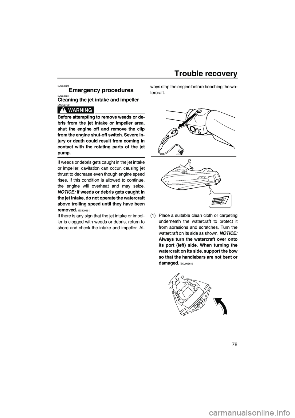
(1) Place a suitable clean cloth or carpeting
underneath the watercraft to protect it
from abrasions and scratches. Turn the
watercraft on its side as shown. NOTICE:
Always turn the watercraft over onto
its port (left) side. When turning the
watercraft on its side, support the bow
so that the handlebars are not bent or
damaged.
[ECJ00661]
UF2L70E0.book Page 78 Thursday, June 19, 2008 8:38 AM
Page 89 of 92
Index
A
Air filter element ....................................... 68
B
Battery ................................................ 44, 63
Battery, checking...................................... 72
Battery, jumping ....................................... 79
Beaching the watercraft ........................... 59
Bilge ......................................................... 43
Boarding alone ......................................... 54
Boarding and starting from a dock ........... 53
Boarding and starting in deep water ........ 53
Boarding and starting in shallow water .... 53
Boarding with passengers ........................ 54
Bow eye ................................................... 28
Builder’s plate............................................. 2
C
Capsized watercraft ................................. 56
Check engine warning indicator ............... 34
Cleaning the watercraft ............................ 64
Cooling water pilot outlet .................... 26, 47
Craft Identification Number (CIN) ............... 1
Cruising limitations ................................... 10
D
Docking the watercraft ............................. 59
E
Emergency procedures ............................ 78
Engine break-in ........................................ 48
Engine compartment ................................ 42
Engine oil ................................................. 39
Engine oil and oil filter .............................. 68
Engine oil level ......................................... 42
Engine overheat warning indicator ........... 33
Engine serial number ................................. 1
Engine shut-off cord (lanyard) .................. 46
Engine shut-off switch .............................. 25
Engine stop switch ................................... 25
Enjoy your watercraft responsibly ............ 18
F
Fire extinguisher....................................... 44
Flushing the cooling system ..................... 62
Front storage compartment ...................... 35
Fuel .......................................................... 38
Fuel and oil............................................... 38
Fuel injection system................................ 73
Fuel level .................................................. 42Fuel level meter ........................................ 31
Fuel level warning indicator ...................... 32
Fuel system, checking .............................. 68
Fuel tank .................................................. 68
Fuel tank filler cap .................................... 24
Fuses, replacing ....................................... 79
G
Getting to know your watercraft ............... 51
Glove compartment .................................. 36
H
Handgrip ................................................... 27
Hazard information ................................... 14
Hood ......................................................... 23
Hour meter/voltmeter ............................... 32
Hull and deck ........................................... 42
I
Identification numbers ................................ 1
J
Jet intake .................................................. 46
Jet intake and impeller, cleaning .............. 78
Jet thrust nozzle angle, checking ............. 68
Jumper cables, connecting ...................... 79
L
Labels, important ........................................ 3
Labels, other .............................................. 7
Labels, warning .......................................... 4
Launching the watercraft .......................... 48
Learning to operate your watercraft ......... 51
Leaving the watercraft .............................. 50
Limitations on who may operate
the watercraft .......................................... 9
“L-MODE” indicator light
(for VX Deluxe/VX Cruiser) ................... 35
Lubrication................................................ 63
Lubrication points ..................................... 71
M
Main components, location of .................. 19
Maintenance and adjustments ................. 64
Model information....................................... 2
Multifunction information center ......... 31, 47
O
Oil pressure warning indicator .................. 33
Operating in weeded areas ...................... 60
Operating your watercraft ......................... 51
Operation ................................................. 48
UF2L70E0.book Page 1 Thursday, June 19, 2008 8:38 AM