engine YAMAHA VX110 2005 User Guide
[x] Cancel search | Manufacturer: YAMAHA, Model Year: 2005, Model line: VX110, Model: YAMAHA VX110 2005Pages: 347, PDF Size: 14.17 MB
Page 31 of 347
2-10
ESPECTIGHTENING TORQUES
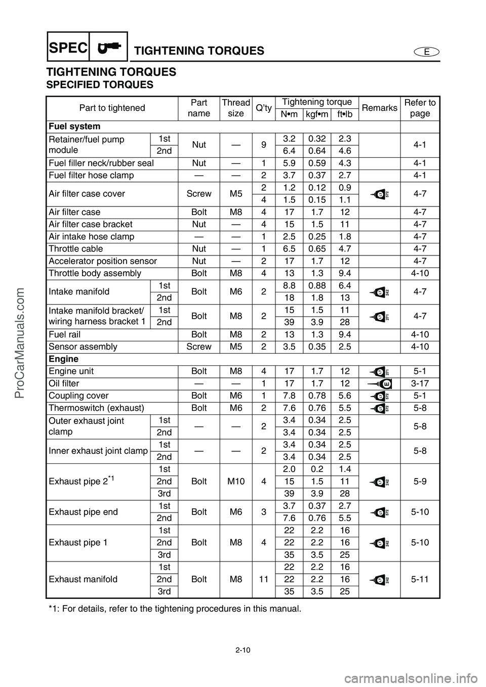
TIGHTENING TORQUES
SPECIFIED TORQUES
Part to tightenedPart
nameThread
sizeQ’tyTightening torque
RemarksRefer to
page
Nmkgfmftlb
Fuel system
Retainer/fuel pump
module1st
Nut—93.20.322.3
4-1
2nd 6.4 0.64 4.6
Fuel filler neck/rubber seal Nut—1 5.9 0.59 4.3 4-1
Fuel filter hose clamp——2 3.7 0.37 2.7 4-1
Air filter case cover Screw M52 1.2 0.12 0.9
572LT4-7
4 1.5 0.15 1.1
Air filter case Bolt M8 4 17 1.7 12 4-7
Air filter case bracket Nut—4 15 1.5 11 4-7
Air intake hose clamp——1 2.5 0.25 1.8 4-7
Throttle cable Nut—1 6.5 0.65 4.7 4-7
Accelerator position sensor Nut—2 17 1.7 12 4-7
Throttle body assembly Bolt M8 4 13 1.3 9.4 4-10
Intake manifold1st
Bolt M6 28.80.886.4
242LT4-7
2nd 18 1.8 13
Intake manifold bracket/
wiring harness bracket 11st
Bolt M8 215 1.5 11
271LT4-7
2nd 39 3.9 28
Fuel rail Bolt M8 2 13 1.3 9.4 4-10
Sensor assembly Screw M5 2 3.5 0.35 2.5 4-10
Engine
Engine unit Bolt M8 4 17 1.7 12
271LT5-1
Oil filter——1171.712
E3-17
Coupling cover Bolt M6 1 7.8 0.78 5.6
572LT5-1
Thermoswitch (exhaust) Bolt M6 2 7.6 0.76 5.5
572LT5-8
Outer exhaust joint
clamp1st
——23.40.342.5
5-8
2nd 3.4 0.34 2.5
Inner exhaust joint clamp1st
——23.40.342.5
5-8
2nd 3.4 0.34 2.5
Exhaust pipe 2
*1 1st
Bolt M10 42.0 0.2 1.4242LT5-9 2nd 15 1.5 11
3rd 39 3.9 28
Exhaust pipe end1st
Bolt M6 33.70.372.7
572LT5-10
2nd 7.6 0.76 5.5
Exhaust pipe 11st
Bolt M8 422 2.2 16
242LT5-10 2nd 22 2.2 16
3rd 35 3.5 25
Exhaust manifold1st
Bolt M8 1122 2.2 16
242LT5-11 2nd 22 2.2 16
3rd 35 3.5 25
*1: For details, refer to the tightening procedures in this manual.
ProCarManuals.com
Page 32 of 347
2-11
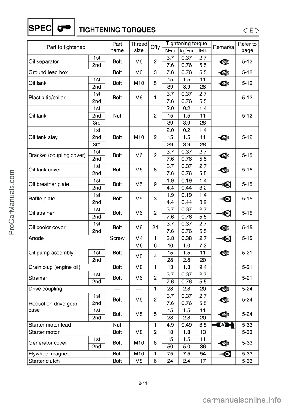
ESPECTIGHTENING TORQUES
Oil separator1st
Bolt M6 23.70.372.7572LT5-12
2nd 7.6 0.76 5.5
Ground lead box Bolt M6 3 7.6 0.76 5.5
572LT5-12
Oil tank1st
Bolt M10 515 1.5 11
572LT5-12
2nd 39 3.9 28
Plastic tie/collar1st
Bolt M6 13.70.372.7
5-12
2nd 7.6 0.76 5.5
Oil tank1st
Nut—22.0 0.2 1.4
5-12 2nd 15 1.5 11
3rd 39 3.9 28
Oil tank stay1st
Bolt M10 22.0 0.2 1.4
572LT5-12 2nd 15 1.5 11
3rd 39 3.9 28
Bracket (coupling cover)1st
Bolt M6 23.70.372.7
572LT5-15
2nd 7.6 0.76 5.5
Oil tank cover1st
Bolt M6 83.70.372.7
572LT5-15
2nd 7.6 0.76 5.5
Oil breather plate1st
Bolt M5 91.90.191.4
E5-15
2nd 4.4 0.44 3.2
Baffle plate1st
Bolt M5 31.90.191.4
E5-15
2nd 4.4 0.44 3.2
Oil strainer1st
Bolt M6 23.70.372.7
E5-15
2nd 7.6 0.76 5.5
Oil cooler cover1st
Bolt M6 243.70.372.7
572LT5-15
2nd 7.6 0.76 5.5
Anode Screw M4 1 3.8 0.38 2.7
E5-15
Oil pump assembly BoltM6 6 10 1.0 7.2
572LT5-21 1st
M8 415 1.5 11
2nd 28 2.8 20
Drain plug (engine oil) Bolt M8 1 13 1.3 9.4 5-21
Strainer1st
Bolt M6 23.70.372.7
5-21
2nd 7.6 0.76 5.5
Drive coupling——1282.820
572LT5-24
Reduction drive gear
case1st
Bolt M6 23.70.372.7
572LT5-24
2nd 7.6 0.76 5.5
1st
Bolt M8 515 1.5 11
572LT5-24
2nd 28 2.8 20
Starter motor lead Nut—1 4.9 0.49 3.5
A5-33
Starter motor Bolt M8 2 18 1.8 13 5-33
Generator cover1st
Bolt M10 815 1.5 11
572LT5-33
2nd 50 5.0 36
Flywheel magneto Bolt M10 1 75 7.5 54
E5-33
Starter clutch Bolt M8 6 24 2.4 17 5-33Part to tightenedPart
nameThread
sizeQ’tyTightening torque
RemarksRefer to
page
Nmkgfmftlb
ProCarManuals.com
Page 33 of 347
2-12
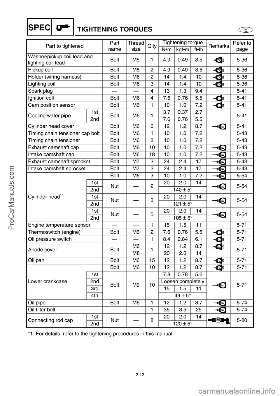
ESPECTIGHTENING TORQUES
Washer/pickup coil lead and
lighting coil leadBolt M5 1 4.9 0.49 3.5242LT5-36
Pickup coil Bolt M5 2 4.9 0.49 3.5
242LT5-36
Holder (wiring harness) Bolt M6 2 14 1.4 10
242LT5-36
Lighting coil Bolt M6 3 14 1.4 10
242LT5-36
Spark plug——4131.39.4 5-41
Ignition coil Bolt M6 4 7.6 0.76 5.5
572LT5-41
Cam position sensor Bolt M6 1 10 1.0 7.2
572LT5-41
Cooling water pipe1st
Bolt M6 13.70.372.7
5-41
2nd 7.6 0.76 5.5
Cylinder head cover Bolt M6 6 12 1.2 8.7
E5-41
Timing chain tensioner cap bolt Bolt M6 1 10 1.0 7.2 5-43
Timing chain tensioner Bolt M6 2 10 1.0 7.2 5-43
Exhaust camshaft cap Bolt M6 10 10 1.0 7.2
E5-43
Intake camshaft cap Bolt M6 18 10 1.0 7.2
E5-43
Exhaust camshaft sprocket Bolt M7 2 24 2.4 17
E5-43
Intake camshaft sprocket Bolt M7 2 24 2.4 17
E5-43
Cylinder head
*1 Bolt M6 3 10 1.0 7.2
E5-54
1st
Nut—220 2.0 14
E5-54
2nd 140 ±
5°
1st
Nut—320 2.0 14
E5-54
2nd 121 ±
5°
1st
Nut—520 2.0 14
E5-54
2nd 105 ±
5°
Engine temperature sensor——1 15 1.5 11 5-71
Thermoswitch (engine) Bolt M6 2 7.6 0.76 5.5
572LT5-71
Oil pressure switch——1 8.4 0.84 6.1
572LT5-71
Anode cover BoltM6
112 1.2 8.7
271LT5-71
M8 20 2.0 14
Oil pan Bolt M6 15 12 1.2 8.7
572LT5-71
Lower crankcaseBolt M6 10 12 1.2 8.7
572LT5-71
1st
Bolt M9 107.80.785.6
E5-71 2nd Loosen completely
3rd 15 1.5 11
4th 49 ±
5°
Oil pipe Bolt M6 1 12 1.2 8.7
E5-74
Oil filter bolt——1353.525
E5-74
Connecting rod cap1st
Nut—820 2.0 14
M5-80
2nd 120 ±
5°
*1: For details, refer to the tightening procedures in this manual.Part to tightenedPart
nameThread
sizeQ’tyTightening torque
RemarksRefer to
page
Nmkgfmftlb
ProCarManuals.com
Page 35 of 347

2-14
ESPECTIGHTENING TORQUES
Shift cable locknut
(Deluxe model only)Nut—1 3.8 0.38 2.7572LT8-23
Steering cable locknut
(steering column side)Nut—1 6.5 0.65 4.7 8-23
Steering cable locknut
(jet pump side)Nut—1 6.8 0.68 4.9
572LT8-23
Steering cable seal Nut—1 5.9 0.59 4.3 8-23
Steering cable bracket Bolt M6 1 6.9 0.69 5.0
572LT8-23
Speed sensor lead grommet Nut—1 5.9 0.59 4.3 8-23
Hinge assembly Bolt M6 2 6.9 0.69 5.0 8-8
Hood lock assembly Bolt M5 2 1.9 0.19 1.4
572LT8-8
Hinge assembly Bolt M6 4 6.9 0.69 5.0
242LT8-8
Lid lock hook Bolt M6 2 6.9 0.69 5.0
242LT8-8
Mirror (Deluxe model only) Nut—4 15 1.5 11 8-8
Shift handle lever
(Deluxe model only)Screw M5 2 3.70.372.7
572LT8-11
Multifunction meter Bolt M5 4 3.9 0.39 2.8
572LT8-11
Engine hatch cover
(Deluxe model only)Bolt M6 1 6.9 0.69 5.0
572LT8-11
Engine hatch cover Bolt M6 8 6.9 0.69 5.0
572LT8-11
Detent plate Bolt M6 2 8.0 0.8 5.8
572LT8-16
Shift lever bracket
(Deluxe model only)Nut—2 15 1.5 11 8-16
Pilot water outlet Nut—1 4.2 0.42 3.0 8-17
Hand grip Nut—4 6.9 0.69 5.0 8-28
Seat bracket Nut—2 15 1.5 11 8-28
Seat lock projection Bolt—1 26 2.6 19 8-28
Seat lock assembly Bolt M6 2 6.4 0.64 4.6
271LT8-28
Plate/rubber hose/exhaust
valveNut—6 5.4 0.54 3.9 8-31
Hose clamp 1——2 3.7 0.37 2.7 8-31
Hose clamp 2——1 3.7 0.37 2.7 8-31
Joint clamp 1 and 4——2 3.7 0.37 2.7 8-31
Joint clamp 2 and 31st
——22.40.241.7
8-31
2nd 2.4 0.24 1.7
Sponson Bolt M810161.612
572LT8-36
Cleat Nut—2
15 1.5 11 8-36
4
Spout Nut—1 5.4 0.54 3.9 8-36
Protector (bow) Nut—5 6.9 0.69 5.0 8-36
Bow eye Bolt M6 2 13 1.3 9.4 8-36
Drain plug/packing Screw M5 4 2.0 0.2 1.4 8-36
Engine mount Bolt M8 8 17 1.7 12
572LT8-38
Engine damper Bolt M6 2 6.6 0.66 4.8
271LT8-38 Part to tightenedPart
nameThread
sizeQ’tyTightening torque
RemarksRefer to
page
Nmkgfmftlb
ProCarManuals.com
Page 40 of 347
2-19
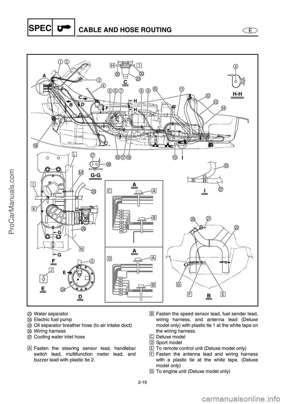
ESPECCABLE AND HOSE ROUTING
12
Ð
Ò
Ó
Õ
Î
ÍÌ
È
É
È
É
Ñ
Ô
3
4
5678
4
B
O
P
5
N
C
D
A09H-H
EFGH
I
P
G
G-G
A
BD
F C
E
JJ
M
C
F
I
I
E
DB
A
A
ÏÐ
H
H
G
G
JK
0
Q
L
Ê
Ë
MWater separator
NElectric fuel pump
OOil separator breather hose (to air intake duct)
PWiring harness
QCooling water inlet hose
ÈFasten the steering sensor lead, handlebar
switch lead, multifunction meter lead, and
buzzer lead with plastic tie 2.ÉFasten the speed sensor lead, fuel sender lead,
wiring harness, and antenna lead (Deluxe
model only) with plastic tie 1 at the white tape on
the wiring harness.
ÊDeluxe model
ËSport model
ÌTo remote control unit (Deluxe model only)
ÍFasten the antenna lead and wiring harness
with a plastic tie at the white tape. (Deluxe
model only)
ÎTo engine unit (Deluxe model only)
ProCarManuals.com
Page 46 of 347
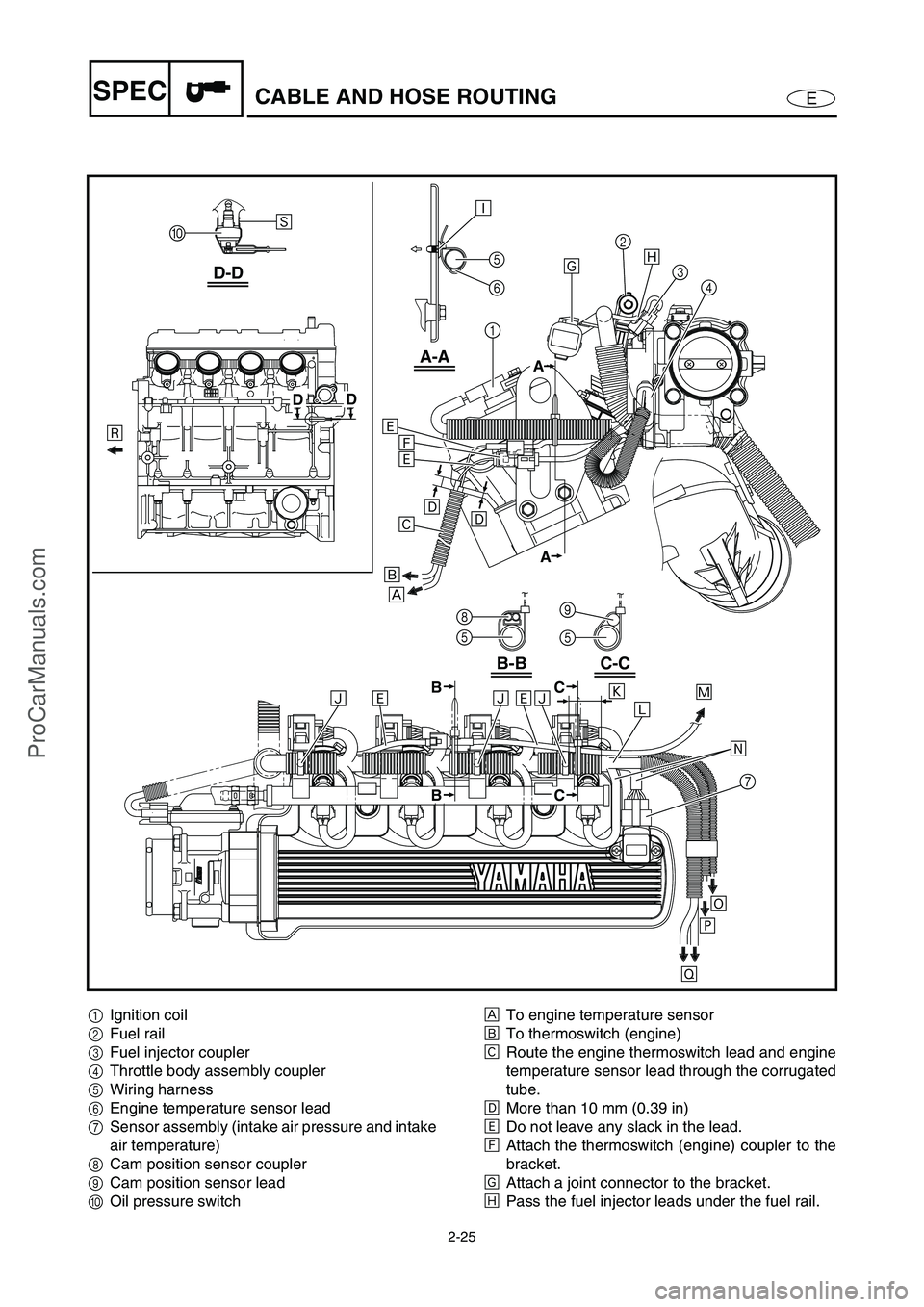
2-25
ESPECCABLE AND HOSE ROUTING
D-D
A-A
B-B
0
8
5
C-C
9
5 Ú
Ù
É
È
Ð
DD
5
6
A
A
1
2
7
34
Î
Ó ÒÌÑÑÌÑ
Ì
Ì
Ë Ë
Ê
Ø×Ö Ô
Õ
Í
Ï
C
CB
B
1Ignition coil
2Fuel rail
3Fuel injector coupler
4Throttle body assembly coupler
5Wiring harness
6Engine temperature sensor lead
7Sensor assembly (intake air pressure and intake
air temperature)
8Cam position sensor coupler
9Cam position sensor lead
0Oil pressure switchÈTo engine temperature sensor
ÉTo thermoswitch (engine)
ÊRoute the engine thermoswitch lead and engine
temperature sensor lead through the corrugated
tube.
ËMore than 10 mm (0.39 in)
ÌDo not leave any slack in the lead.
ÍAttach the thermoswitch (engine) coupler to the
bracket.
ÎAttach a joint connector to the bracket.
ÏPass the fuel injector leads under the fuel rail.
ProCarManuals.com
Page 47 of 347
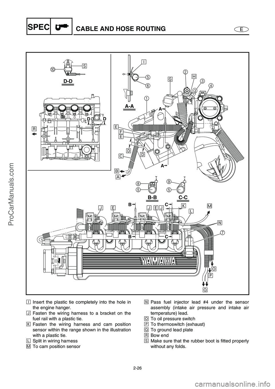
2-26
ESPECCABLE AND HOSE ROUTING
D-D
A-A
B-B
0
8
5
C-C
9
5 Ú
Ù
É
È
Ð
DD
5
6
A
A
1
2
7
34
Î
Ó ÒÌÑÑÌÑ
Ì
Ì
Ë Ë
Ê
Ø×Ö Ô
Õ
Í
Ï
C
CB
B
ÐInsert the plastic tie completely into the hole in
the engine hanger.
ÑFasten the wiring harness to a bracket on the
fuel rail with a plastic tie.
ÒFasten the wiring harness and cam position
sensor within the range shown in the illustration
with a plastic tie.
ÓSplit in wiring harness
ÔTo cam position sensorÕPass fuel injector lead #4 under the sensor
assembly (intake air pressure and intake air
temperature) lead.
ÖTo oil pressure switch
×To thermoswitch (exhaust)
ØTo ground lead plate
ÙBow end
ÚMake sure that the rubber boot is fitted properly
without any folds.
ProCarManuals.com
Page 49 of 347
E
INSP
ADJ
1
2
3
4
5
6
7
8
9
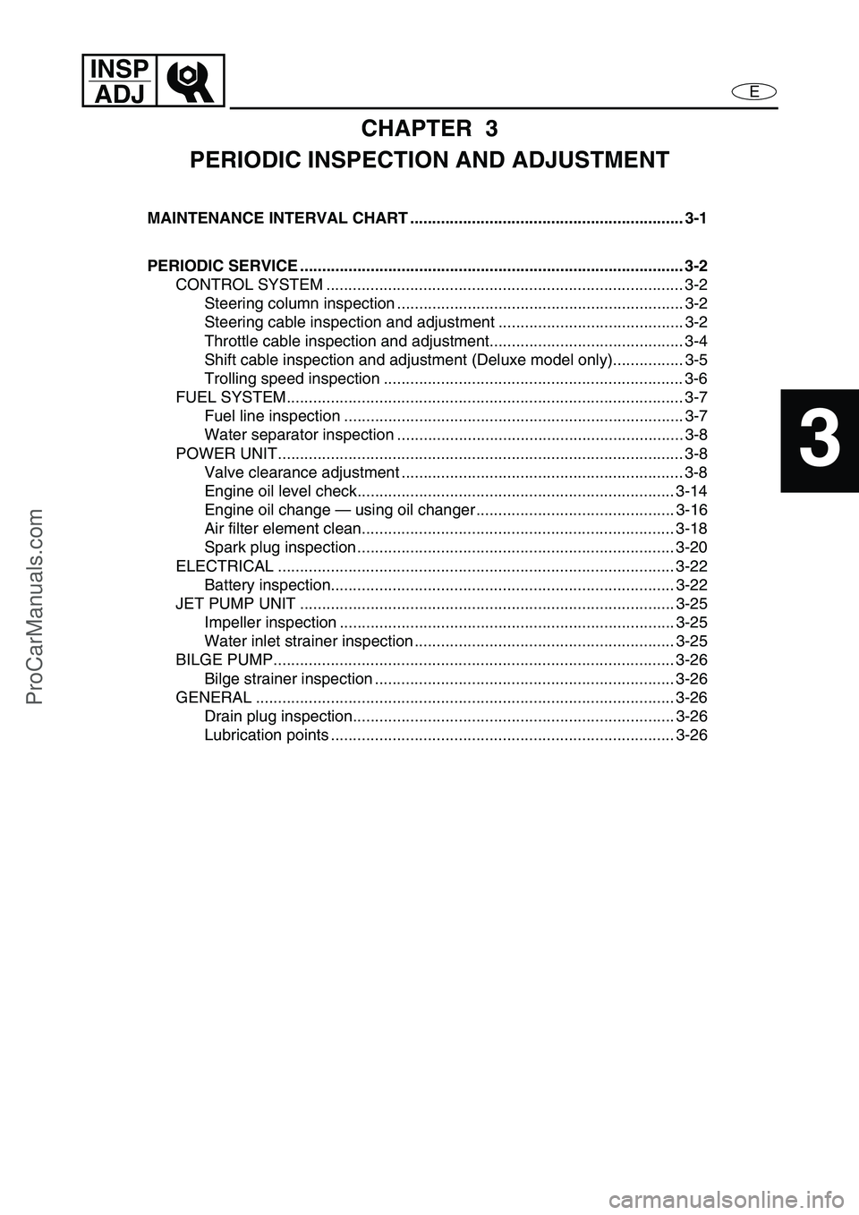
CHAPTER 3
PERIODIC INSPECTION AND ADJUSTMENT
MAINTENANCE INTERVAL CHART .............................................................. 3-1
PERIODIC SERVICE ....................................................................................... 3-2
CONTROL SYSTEM ................................................................................. 3-2
Steering column inspection ................................................................. 3-2
Steering cable inspection and adjustment .......................................... 3-2
Throttle cable inspection and adjustment............................................ 3-4
Shift cable inspection and adjustment (Deluxe model only)................ 3-5
Trolling speed inspection .................................................................... 3-6
FUEL SYSTEM.......................................................................................... 3-7
Fuel line inspection ............................................................................. 3-7
Water separator inspection ................................................................. 3-8
POWER UNIT............................................................................................ 3-8
Valve clearance adjustment ................................................................ 3-8
Engine oil level check........................................................................ 3-14
Engine oil change — using oil changer ............................................. 3-16
Air filter element clean....................................................................... 3-18
Spark plug inspection ........................................................................ 3-20
ELECTRICAL .......................................................................................... 3-22
Battery inspection.............................................................................. 3-22
JET PUMP UNIT ..................................................................................... 3-25
Impeller inspection ............................................................................ 3-25
Water inlet strainer inspection ........................................................... 3-25
BILGE PUMP........................................................................................... 3-26
Bilge strainer inspection .................................................................... 3-26
GENERAL ............................................................................................... 3-26
Drain plug inspection......................................................................... 3-26
Lubrication points .............................................................................. 3-26
ProCarManuals.com
Page 50 of 347
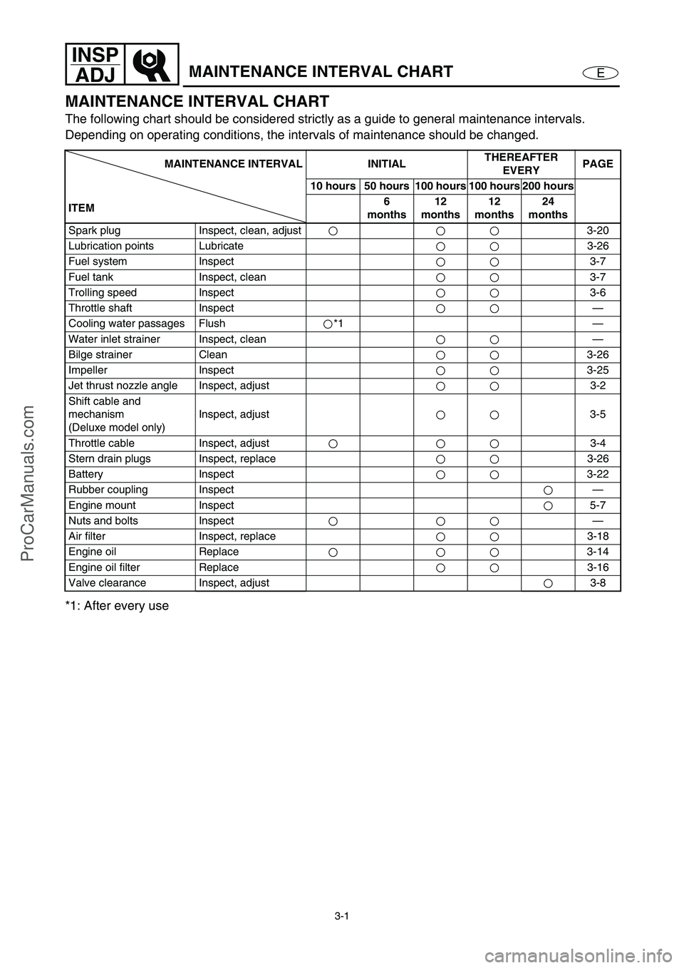
3-1
E
INSP
ADJ
MAINTENANCE INTERVAL CHART
MAINTENANCE INTERVAL CHART
The following chart should be considered strictly as a guide to general maintenance intervals.
Depending on operating conditions, the intervals of maintenance should be changed.
*1: After every use
MAINTENANCE INTERVAL INITIALTHEREAFTER
EVERYPAGE
10 hours 50 hours 100 hours 100 hours 200 hours
ITEM6
months12
months12
months24
months
Spark plug Inspect, clean, adjust 3-20
Lubrication points Lubricate 3-26
Fuel system Inspect3-7
Fuel tank Inspect, clean 3-7
Trolling speed Inspect3-6
Throttle shaft Inspect—
Cooling water passages Flush *1 —
Water inlet strainer Inspect, clean —
Bilge strainer Clean3-26
Impeller Inspect3-25
Jet thrust nozzle angle Inspect, adjust 3-2
Shift cable and
mechanism
(Deluxe model only)Inspect, adjust 3-5
Throttle cable Inspect, adjust 3-4
Stern drain plugs Inspect, replace 3-26
Battery Inspect 3-22
Rubber coupling Inspect—
Engine mount Inspect5-7
Nuts and bolts Inspect—
Air filter Inspect, replace 3-18
Engine oil Replace 3-14
Engine oil filter Replace 3-16
Valve clearance Inspect, adjust 3-8
ProCarManuals.com
Page 55 of 347

3-6
E
INSP
ADJ
CONTROL SYSTEM
Turn out the cable joint nine times a
to
extend the cable 7 mm (0.28 in) from the
aligned position.
WARNING
The cable joint must be screwed in more
than 8 mm (0.31 in).
Connect the cable joint and tighten the
locknut.
T R..
Locknut:
3.8 N m (0.38 kgf m, 2.7 ft lb)
Trolling speed inspection
1. Inspect:
Trolling speed
Trolling speed:
1,550–1,750 r/min
Checking steps (watercraft in water):
Start the engine and allow it to warm up
for 15 minutes.
Check the engine trolling speed using the
tachometer of the multifunction meter or
using the Yamaha Diagnostic System.
ProCarManuals.com