service YAMAHA VX110 2005 User Guide
[x] Cancel search | Manufacturer: YAMAHA, Model Year: 2005, Model line: VX110, Model: YAMAHA VX110 2005Pages: 347, PDF Size: 14.17 MB
Page 16 of 347
1-7
E
GEN
INFO
SPECIAL SERVICE TOOLS
K
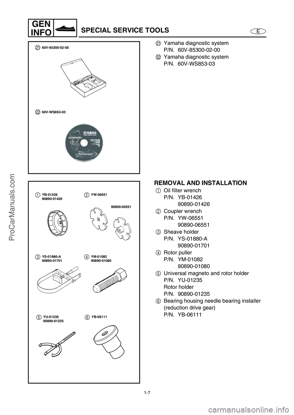
Yamaha diagnostic system
P/N. 60V-85300-02-00
L
Yamaha diagnostic system
P/N. 60V-WS853-03
L
60V-WS853-03
K60V-85300-02-00
REMOVAL AND INSTALLATION
1
Oil filter wrench
P/N. YB-01426
90890-01426
2
Coupler wrench
P/N. YW-06551
90890-06551
3
Sheave holder
P/N. YS-01880-A
90890-01701
4
Rotor puller
P/N. YM-01082
90890-01080
5
Universal magneto and rotor holder
P/N. YU-01235
Rotor holder
P/N. 90890-01235
6
Bearing housing needle bearing installer
(reduction drive gear)
P/N. YB-0611112
34YB-01426
90890-01426YW-06551
90890-06551
YS-01880-A
90890-01701YM-01082
90890-01080
56YU-01235
90890-01235YB-06111
ProCarManuals.com
Page 17 of 347
1-8
E
GEN
INFO
SPECIAL SERVICE TOOLS
7
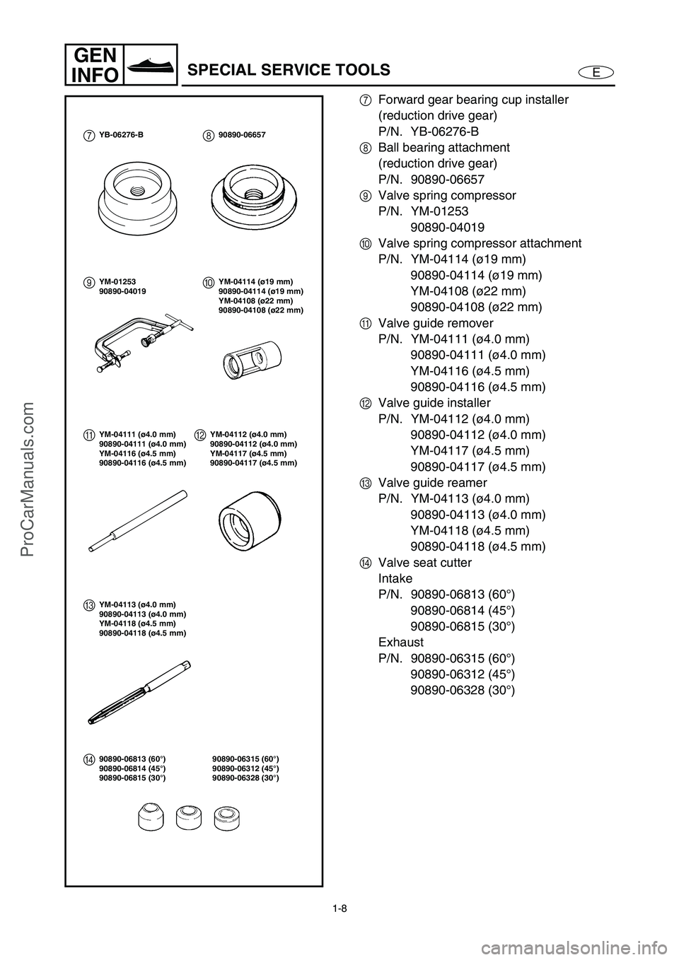
Forward gear bearing cup installer
(reduction drive gear)
P/N. YB-06276-B
8
Ball bearing attachment
(reduction drive gear)
P/N. 90890-06657
9
Valve spring compressor
P/N. YM-01253
90890-04019
0
Valve spring compressor attachment
P/N. YM-04114 (ø19 mm)
90890-04114 (ø19 mm)
YM-04108 (ø22 mm)
90890-04108 (ø22 mm)
A
Valve guide remover
P/N. YM-04111 (ø4.0 mm)
90890-04111 (ø4.0 mm)
YM-04116 (ø4.5 mm)
90890-04116 (ø4.5 mm)
B
Valve guide installer
P/N. YM-04112 (ø4.0 mm)
90890-04112 (ø4.0 mm)
YM-04117 (ø4.5 mm)
90890-04117 (ø4.5 mm)
C
Valve guide reamer
P/N. YM-04113 (ø4.0 mm)
90890-04113 (ø4.0 mm)
YM-04118 (ø4.5 mm)
90890-04118 (ø4.5 mm)
D
Valve seat cutter
Intake
P/N. 90890-06813 (60°)
90890-06814 (45°)
90890-06815 (30°)
Exhaust
P/N. 90890-06315 (60°)
90890-06312 (45°)
90890-06328 (30°)
0
AYM-04114 (ø19 mm)
90890-04114 (ø19 mm)
YM-04108 (ø22 mm)
90890-04108 (ø22 mm)
YM-04111 (ø4.0 mm)
90890-04111 (ø4.0 mm)
YM-04116 (ø4.5 mm)
90890-04116 (ø4.5 mm)
7YB-06276-B8
990890-06657
YM-01253
90890-04019
B
CYM-04112 (ø4.0 mm)
90890-04112 (ø4.0 mm)
YM-04117 (ø4.5 mm)
90890-04117 (ø4.5 mm)
YM-04113 (ø4.0 mm)
90890-04113 (ø4.0 mm)
YM-04118 (ø4.5 mm)
90890-04118 (ø4.5 mm)
90890-06315 (60°)
90890-06312 (45°)
90890-06328 (30°)
D90890-06813 (60°)
90890-06814 (45°)
90890-06815 (30°)
ProCarManuals.com
Page 18 of 347
1-9
E
GEN
INFO
SPECIAL SERVICE TOOLS
E
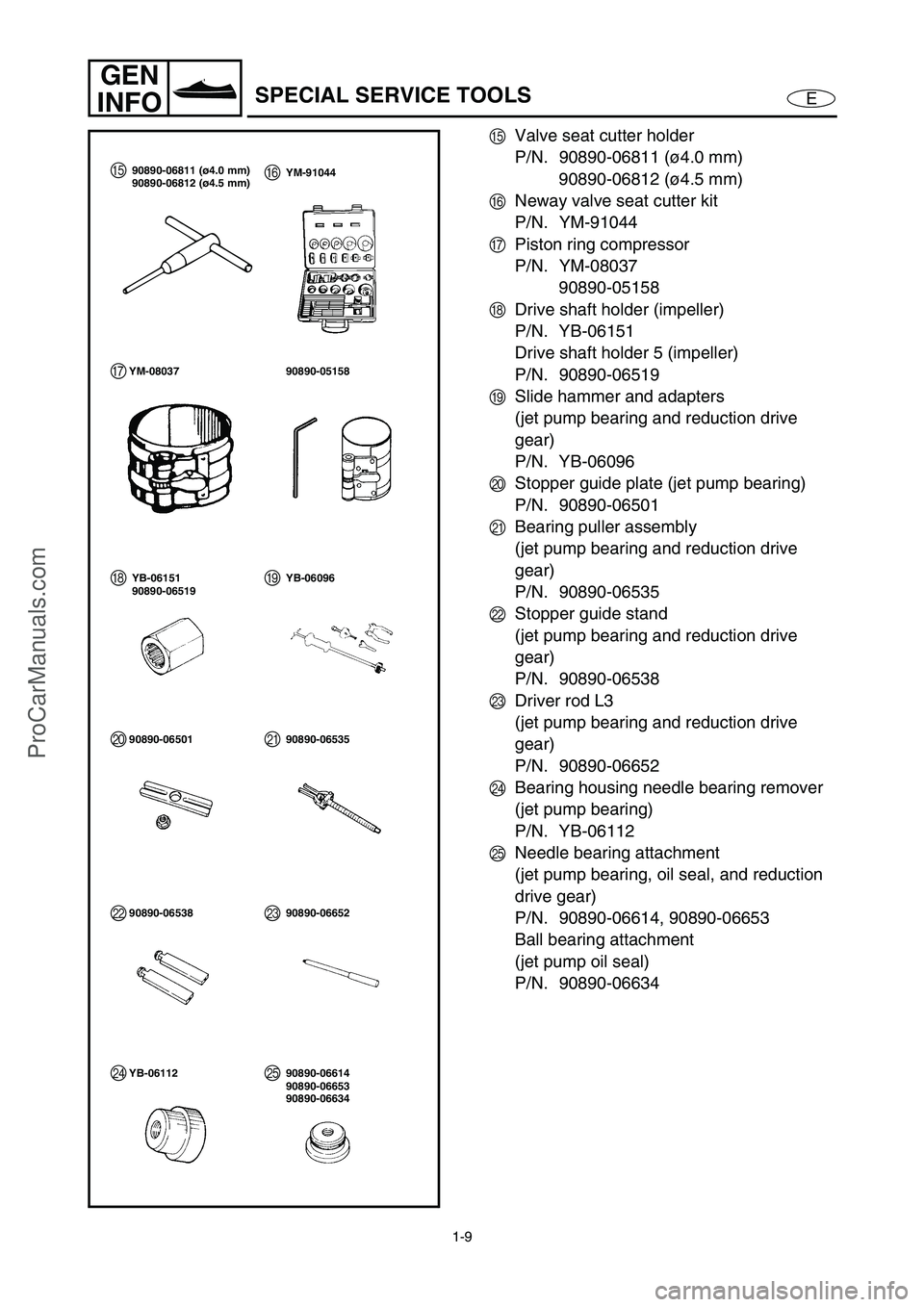
Valve seat cutter holder
P/N. 90890-06811 (ø4.0 mm)
90890-06812 (ø4.5 mm)
F
Neway valve seat cutter kit
P/N. YM-91044
G
Piston ring compressor
P/N. YM-08037
90890-05158
H
Drive shaft holder (impeller)
P/N. YB-06151
Drive shaft holder 5 (impeller)
P/N. 90890-06519
I
Slide hammer and adapters
(jet pump bearing and reduction drive
gear)
P/N. YB-06096
J
Stopper guide plate (jet pump bearing)
P/N. 90890-06501
K
Bearing puller assembly
(jet pump bearing and reduction drive
gear)
P/N. 90890-06535
L
Stopper guide stand
(jet pump bearing and reduction drive
gear)
P/N. 90890-06538
M
Driver rod L3
(jet pump bearing and reduction drive
gear)
P/N. 90890-06652
N
Bearing housing needle bearing remover
(jet pump bearing)
P/N. YB-06112
O
Needle bearing attachment
(jet pump bearing, oil seal, and reduction
drive gear)
P/N. 90890-06614, 90890-06653
Ball bearing attachment
(jet pump oil seal)
P/N. 90890-06634
YM-08037 90890-05158
YB-06096
90890-06501 90890-06535
E
G
HI
JK90890-06811 (ø4.0 mm)
90890-06812 (ø4.5 mm)
YB-06151
90890-06519YM-91044F
90890-06538 90890-06652LM
YB-06112 90890-06614NO90890-06653
90890-06634
ProCarManuals.com
Page 19 of 347
1-10
E
GEN
INFO
SPECIAL SERVICE TOOLS
P
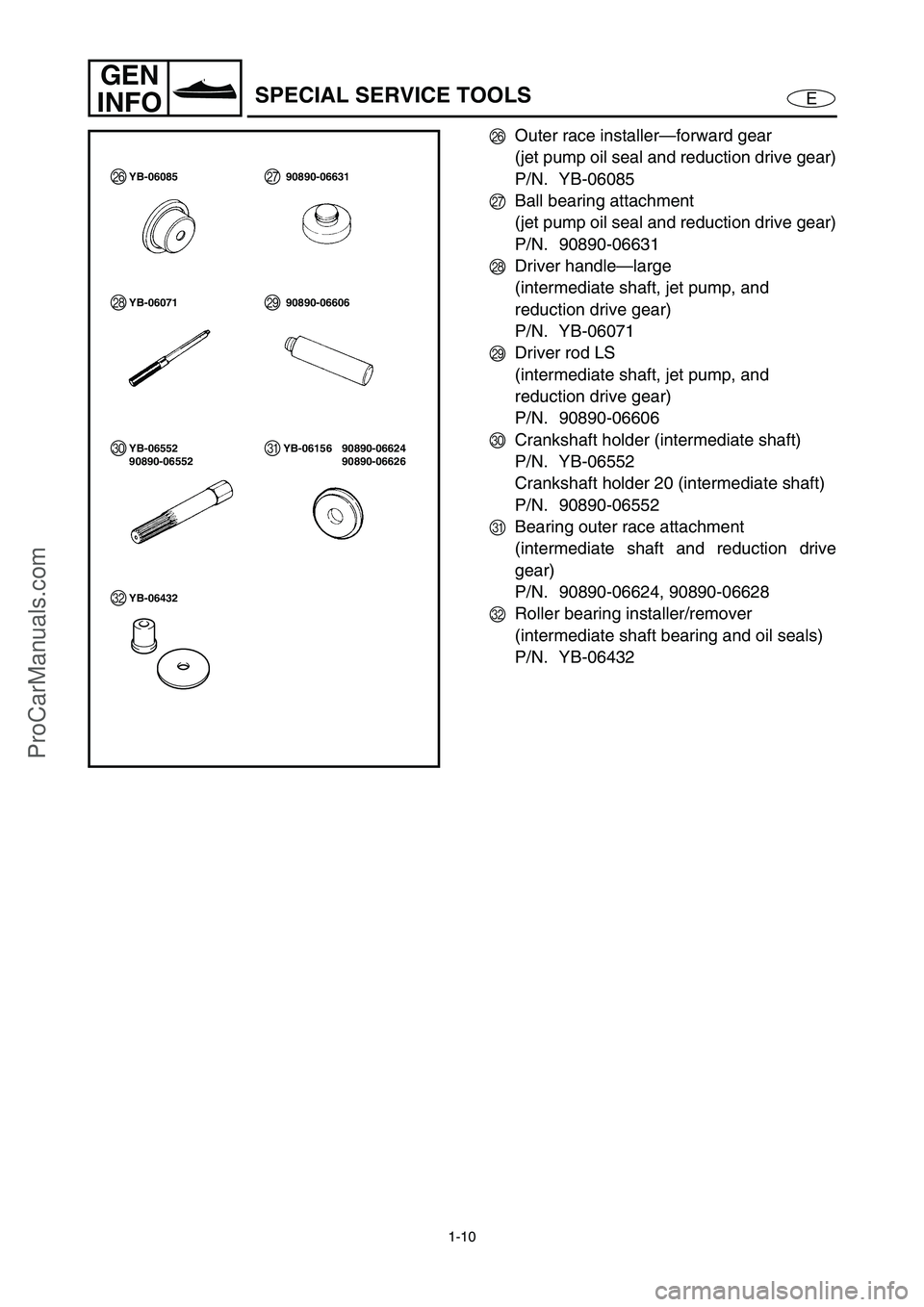
Outer race installer—forward gear
(jet pump oil seal and reduction drive gear)
P/N. YB-06085
Q
Ball bearing attachment
(jet pump oil seal and reduction drive gear)
P/N. 90890-06631
R
Driver handle—large
(intermediate shaft, jet pump, and
reduction drive gear)
P/N. YB-06071
S
Driver rod LS
(intermediate shaft, jet pump, and
reduction drive gear)
P/N. 90890-06606
T
Crankshaft holder (intermediate shaft)
P/N. YB-06552
Crankshaft holder 20 (intermediate shaft)
P/N. 90890-06552
U
Bearing outer race attachment
(intermediate shaft and reduction drive
gear)
P/N. 90890-06624, 90890-06628
V
Roller bearing installer/remover
(intermediate shaft bearing and oil seals)
P/N. YB-06432
YB-06071 90890-06606 RS
YB-06552
90890-06552T
YB-06085 P90890-06631Q
90890-06624 YB-06156U90890-06626
YB-06432V
ProCarManuals.com
Page 49 of 347
E
INSP
ADJ
1
2
3
4
5
6
7
8
9
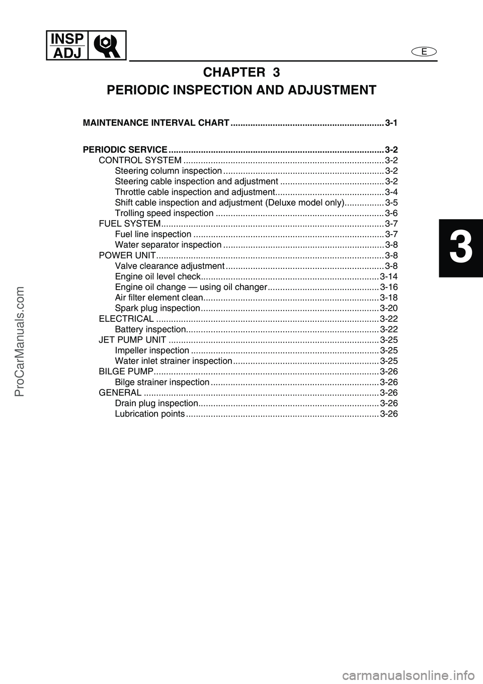
CHAPTER 3
PERIODIC INSPECTION AND ADJUSTMENT
MAINTENANCE INTERVAL CHART .............................................................. 3-1
PERIODIC SERVICE ....................................................................................... 3-2
CONTROL SYSTEM ................................................................................. 3-2
Steering column inspection ................................................................. 3-2
Steering cable inspection and adjustment .......................................... 3-2
Throttle cable inspection and adjustment............................................ 3-4
Shift cable inspection and adjustment (Deluxe model only)................ 3-5
Trolling speed inspection .................................................................... 3-6
FUEL SYSTEM.......................................................................................... 3-7
Fuel line inspection ............................................................................. 3-7
Water separator inspection ................................................................. 3-8
POWER UNIT............................................................................................ 3-8
Valve clearance adjustment ................................................................ 3-8
Engine oil level check........................................................................ 3-14
Engine oil change — using oil changer ............................................. 3-16
Air filter element clean....................................................................... 3-18
Spark plug inspection ........................................................................ 3-20
ELECTRICAL .......................................................................................... 3-22
Battery inspection.............................................................................. 3-22
JET PUMP UNIT ..................................................................................... 3-25
Impeller inspection ............................................................................ 3-25
Water inlet strainer inspection ........................................................... 3-25
BILGE PUMP........................................................................................... 3-26
Bilge strainer inspection .................................................................... 3-26
GENERAL ............................................................................................... 3-26
Drain plug inspection......................................................................... 3-26
Lubrication points .............................................................................. 3-26
ProCarManuals.com
Page 51 of 347
3-2
E
INSP
ADJ
CONTROL SYSTEM
PERIODIC SERVICE
CONTROL SYSTEM
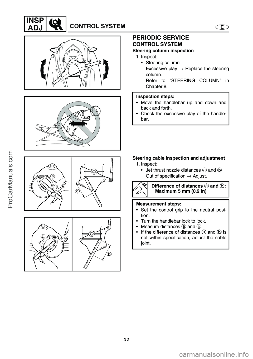
Steering column inspection
1. Inspect:
Steering column
Excessive play →
Replace the steering
column.
Refer to “STEERING COLUMN” in
Chapter 8.
Inspection steps:
Move the handlebar up and down and
back and forth.
Check the excessive play of the handle-
bar.
Steering cable inspection and adjustment
1. Inspect:
Jet thrust nozzle distances a
and b
Out of specification →
Adjust.
Difference of distances
a and
b:
Maximum 5 mm (0.2 in)
Measurement steps:
Set the control grip to the neutral posi-
tion.
Turn the handlebar lock to lock.
Measure distances a
and b
.
If the difference of distances a
and b
is
not within specification, adjust the cable
joint.
ProCarManuals.com
Page 77 of 347
EFUEL
1
2
3
4
5
6
7
8
9
CHAPTER 4
FUEL SYSTEM
FUEL TANK AND FUEL PUMP MODULE...................................................... 4-1
EXPLODED DIAGRAM ............................................................................. 4-1
REMOVAL AND INSTALLATION CHART ................................................ 4-1
SERVICE POINTS .................................................................................... 4-4
Fuel hose disconnection ..................................................................... 4-4
Fuel pump module removal................................................................. 4-4
Check valve inspection ....................................................................... 4-4
Fuel sender inspection ........................................................................ 4-5
Fuel tank inspection ............................................................................ 4-5
Fuel hose inspection ........................................................................... 4-5
Fuel pump filter inspection .................................................................. 4-5
Fuel pump module installation ............................................................ 4-6
Fuel hose connect ............................................................................... 4-6
FUEL INJECTION SYSTEM ............................................................................ 4-7
EXPLODED DIAGRAM ............................................................................. 4-7
REMOVAL AND INSTALLATION CHART ................................................ 4-7
THROTTLE BODY ASSEMBLY AND INTAKE MANIFOLD ........................ 4-10
EXPLODED DIAGRAM ........................................................................... 4-10
REMOVAL AND INSTALLATION CHART .............................................. 4-10
SERVICE POINTS .................................................................................. 4-12
Fuel hose clamps removal ................................................................ 4-12
Hose clamps installation ................................................................... 4-12
Fuel hose disconnection ................................................................... 4-12
Fuel line inspection ........................................................................... 4-13
Fuel hose installation (replacing with new fuel hose) ........................ 4-14
Fuel hose connection ........................................................................ 4-14
Fuel injectors inspection.................................................................... 4-15
Throttle body assembly inspection .................................................... 4-15
Accelerator position sensor inspection.............................................. 4-15
Intake assembly installation .............................................................. 4-16
Air filter case assembly installation ................................................... 4-17
Fuel pressure measurement ............................................................. 4-17
ProCarManuals.com
Page 78 of 347
4-1
EFUELFUEL TANK AND FUEL PUMP MODULE
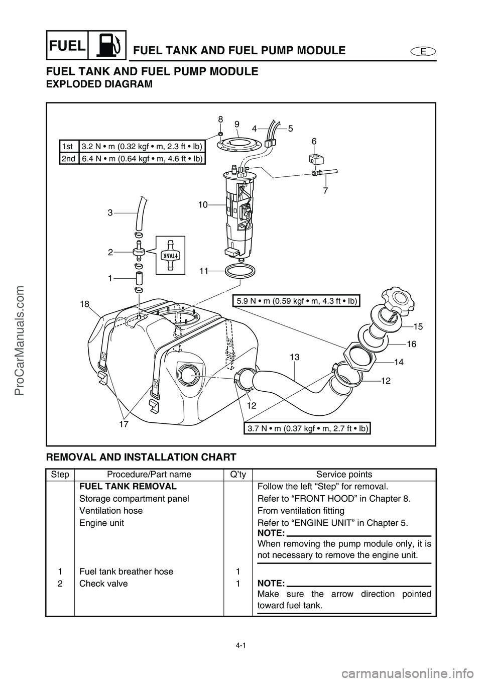
FUEL TANK AND FUEL PUMP MODULE
EXPLODED DIAGRAM
REMOVAL AND INSTALLATION CHART
Step Procedure/Part name Q’ty Service points
FUEL TANK REMOVAL
Follow the left “Step” for removal.
Storage compartment panel Refer to “FRONT HOOD” in Chapter 8.
Ventilation hose From ventilation fitting
Engine unit Refer to “ENGINE UNIT” in Chapter 5.
NOTE:
When removing the pump module only, it is
not necessary to remove the engine unit.
1 Fuel tank breather hose 1
2 Check valve 1
NOTE:
Make sure the arrow direction pointed
toward fuel tank.
7
10
11 3
2
1
18
17121315
16
14
12 6 5
4 8
9
2nd 6.4 N • m (0.64 kgf m, 4.6 ft Ib) 1st 3.2 N m (0.32 kgf m, 2.3 ft Ib)
3.7 N m (0.37 kgf m, 2.7 ft Ib)
5.9 N m (0.59 kgf m, 4.3 ft Ib)
ProCarManuals.com
Page 79 of 347
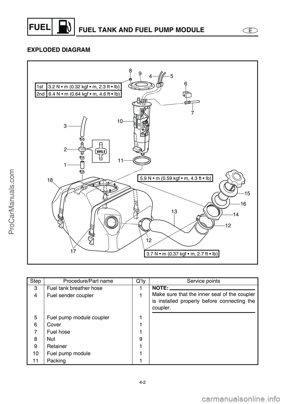
4-2
EFUELFUEL TANK AND FUEL PUMP MODULE
EXPLODED DIAGRAM
Step Procedure/Part name Q’ty Service points
3 Fuel tank breather hose 1
NOTE:
Make sure that the inner seal of the coupler
is installed properly before connecting the
coupler. 4 Fuel sender coupler 1
5 Fuel pump module coupler 1
6 Cover 1
7 Fuel hose 1
8Nut 9
9 Retainer 1
10 Fuel pump module 1
11 Packing 1
7
10
11 3
2
1
18
17121315
16
14
12 6 5
4 8
9
2nd 6.4 N m (0.64 kgf m, 4.6 ft Ib) 1st 3.2 N m (0.32 kgf m, 2.3 ft Ib)
3.7 N m (0.37 kgf m, 2.7 ft Ib)
5.9 N m (0.59 kgf m, 4.3 ft Ib)
ProCarManuals.com
Page 80 of 347
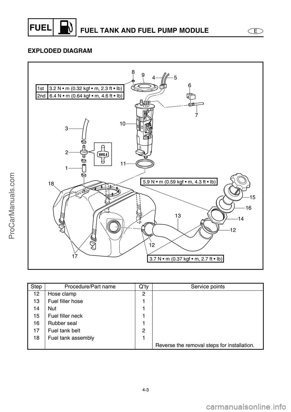
4-3
EFUELFUEL TANK AND FUEL PUMP MODULE
EXPLODED DIAGRAM
Step Procedure/Part name Q’ty Service points
12 Hose clamp 2
13 Fuel filler hose 1
14 Nut 1
15 Fuel filler neck 1
16 Rubber seal 1
17 Fuel tank belt 2
18 Fuel tank assembly 1
Reverse the removal steps for installation.
7
10
11 3
2
1
18
17121315
16
14
12 6 5
4 8
9
2nd 6.4 N m (0.64 kgf m, 4.6 ft Ib) 1st 3.2 N m (0.32 kgf m, 2.3 ft Ib)
3.7 N m (0.37 kgf m, 2.7 ft Ib)
5.9 N m (0.59 kgf m, 4.3 ft Ib)
ProCarManuals.com