engine YAMAHA WOLVERINE 2016 Workshop Manual
[x] Cancel search | Manufacturer: YAMAHA, Model Year: 2016, Model line: WOLVERINE, Model: YAMAHA WOLVERINE 2016Pages: 192, PDF Size: 4.38 MB
Page 169 of 192
8-54
8
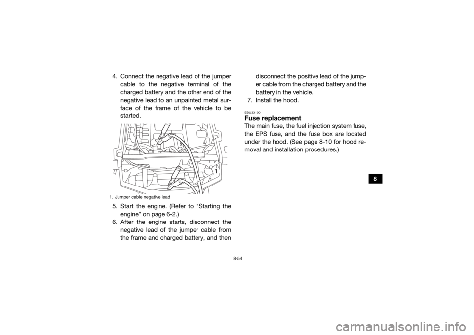
4. Connect the negative lead of the jumpercable to the negative terminal of the
charged battery and the other end of the
negative lead to an unpainted metal sur-
face of the frame of the vehicle to be
started.
5. Start the engine. (Refer to “Starting the engine” on page 6-2.)
6. After the engine starts, disconnect the
negative lead of the jumper cable from
the frame and charged battery, and then disconnect the positive lead of the jump-
er cable from the charged battery and the
battery in the vehicle.
7. Install the hood.
EBU33100Fuse replacementThe main fuse, the fuel injection system fuse,
the EPS fuse, and the fuse box are located
under the hood. (See page 8-10 for hood re-
moval and installation procedures.)
1. Jumper cable negative lead
1
UBN57AE0.book Page 54 Tuesday, November 24, 2015 1:42 PM
Page 177 of 192
8-62
8
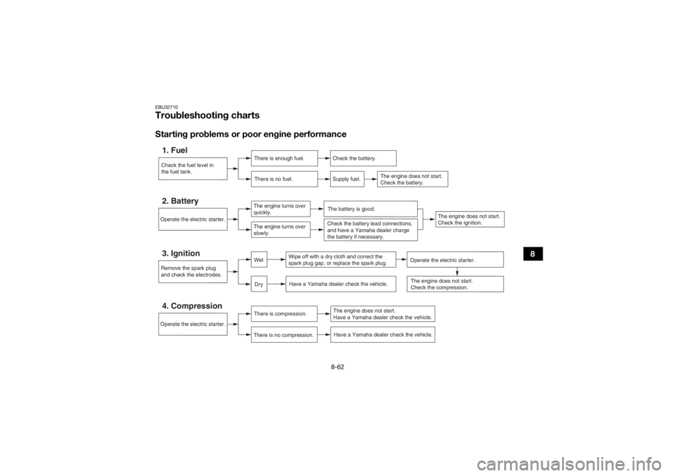
EBU32710Troubleshooting chartsStarting problems or poor engine performanceCheck the fuel level in
the fuel tank.1. Fuel
There is enough fuel.
There is no fuel.
Check the battery.
Supply fuel.
The engine does not start.
Check the battery.
Operate the electric starter.4. Compression
There is compression.
There is no compression.
The engine does not start.
Have a Yamaha dealer check the vehicle.Have a Yamaha dealer check the vehicle.
Remove the spark plug
and check the electrodes.3. Ignition
Wipe off with a dry cloth and correct the
spark plug gap, or replace the spark plug. Have a Yamaha dealer check the vehicle.
The engine does not start.
Check the compression.
Operate the electric starter.2. Battery
The engine turns over
quickly.
The engine turns over
slowly.
The battery is good.
DryWet
Operate the electric starter.
Check the battery lead connections,
and have a Yamaha dealer charge
the battery if necessary.
The engine does not start.
Check the ignition.
UBN57AE0.book Page 62 Tuesday, November 24, 2015 1:42 PM
Page 178 of 192
8-63
8
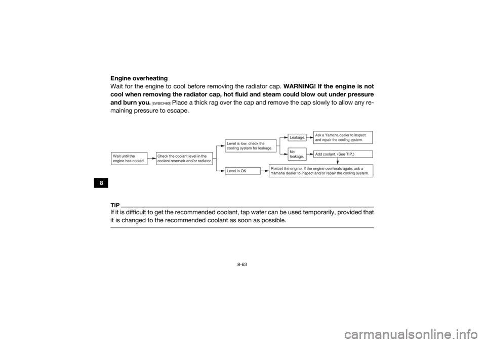
Engine overheating
Wait for the engine to cool before removing the radiator cap. WARNING! If the engine is not
cool when removing the radiator cap, hot fluid and steam could blow out under pressure
and burn you.
[EWB03460]
Place a thick rag over the cap and remove the cap slowly to allow any re-
maining pressure to escape.
TIPIf it is difficult to get the recommended coolant, tap water can be used temporarily, provided that
it is changed to the recommende d coolant as soon as possible. Wait until the
engine has cooled.
Check the coolant level in the
coolant reservoir and/or radiator.
Level is OK.Level is low, check the
cooling system for leakage.
No
leakage.Leakage.
Ask a Yamaha dealer to inspect
and repair the cooling system.Add coolant. (See TIP.)
Restart the engine. If the engine overheats again, ask a
Yamaha dealer to inspect and/or repair the cooling system.
UBN57AE0.book Page 63 Tuesday, November 24, 2015 1:42 PM
Page 179 of 192

9-1
9
EBU32720
CLEANING AND STORAGE
EBU33681CleaningFrequent, thorough cleaning of your vehicle
will not only enhance its appearance but will
improve its general performance and extend
the useful life of many components.1. Before cleaning the vehicle: a. Block off the end of the exhaust pipeto prevent water entry. A plastic bag
and strong rubber band may be used.
b. Make sure the spark plug and all filler caps are properly installed.
2. If the engine case is excessively greasy, apply degreaser with a paint brush. Do
not apply degreaser to the wheel axles.
3. Rinse the dirt and degreaser off with a garden hose. Use only enough pressure
to do the job. WARNING! Test the
brakes after washing. Apply the
brakes several times at slow speeds to
let friction dry the brakes. Wet brakes may have reduced stopping ability, in-
creasing the chance of an accident.
[EWB03471]
NOTICE: Excessive water pres-
sure may cause water seepage and
deterioration of wheel bearings,
brakes, transmission seals and electri-
cal devices. Many expensive repair
bills have resulted from improper high-
pressure detergent applications such
as those available in coin-operated car
washers.
[ECB00712]
TIPThe tailgate can be removed to make it easier
to clean the cargo bed. To separate the tail-
gate from the cargo bed, unhook the latches,
and then pull up the tailgate. (See page 4-22
for tailgate removal and installation proce-
dures.)
UBN57AE0.book Page 1 Tuesday, November 24, 2015 1:42 PM
Page 180 of 192
9-2
9
4. Once the majority of the dirt has beenhosed off, wash all surfaces with warm
water and mild, detergent-type soap. An
old toothbrush or bottle brush is handy
for hard-to-get-at places.
5. Rinse the vehicle off immediately with
clean water and dry all surfaces with a
clean chamois towel or soft, absorbent
cloth.
6. Clean the seats with a vinyl upholstery cleaner to keep the covers pliable and
glossy.
7. Automotive-type wax may be applied to all painted and chrome-plated surfaces.
Avoid combination cleaner-waxes. Many
contain abrasives which may scratch the
paint or protective finish. When finished,
start the engine and let it idle for several
minutes.
EBU36120StorageLong term storage (60 days or more) of your
vehicle will require some preventive proce-
dures to guard against deterioration. Make
any necessary repairs be fore storing the vehi-
cle.
After thoroughly cleaning the vehicle, prepare
for storage as follows: 1. Fill the fuel tank with fresh fuel and add the specified amount of Fuel Med Rx or
another high-quality fuel stabilizer prod-
uct. Follow the instructions on the prod-
uct label. Operate the vehicle for at least
5 minutes to distribute treated fuel
through the fuel system.
2. Remove the spark plug and pour one ta- blespoon of fresh engine oil into the cyl-
inder and then re-install the spark plug.Specified amount:1 oz of stabilizer to each gallon of fuel (or
7.5 ml of stabilizer to each liter of fuel)
UBN57AE0.book Page 2 Tuesday, November 24, 2015 1:42 PM
Page 181 of 192
9-3
9
Remove the spark plug wire and ground
it. Operate the electric starter to turn the
engine over several times and coat the
cylinder walls with oil.
3. Lubricate all control cables.
4. Put the frame on stands or blocks to raise
all wheels off the ground.
5. Tie a plastic bag over the exhaust pipe
outlet to prevent moisture from entering.
6. If storing in a humid or salt-air atmo- sphere, coat all exposed metal surfaces
with a light film of oil. Do not apply oil to
any rubber parts or the seat covers.
7. Remove the battery and charge it. Store
it in a dry place and recharge it once a
month. Do not store the battery in an ex-
cessively warm or cold place [less than 0
°C (30 °F) or more than 30 °C (90 °F)].
Use of fuel stabilizer eliminates the need to
drain the fuel system. Consult a Yamaha
dealer if the fuel system needs to be drained.
UBN57AE0.book Page 3 Tuesday, November 24, 2015 1:42 PM
Page 182 of 192

10-1
10
EBU32750
SPECIFICATIONS
Dimensions:Overall length:2970 mm (116.9 in)
Overall width: 1540 mm (60.6 in)
Overall height:
1885 mm (74.2 in)
Wheelbase: 2065 mm (81.3 in)
Ground clearance: 290 mm (11.4 in)
Minimum turning radius:
4600 mm (181 in)Weight:Curb weight:637.0 kg (1404 lb)Noise and vibration level:Noise level (77/311/EEC):80.0 dB(A) at 3125 r/min (EUR,FRA,GBR)
Uncertainty of measurement: 3.0 dB(A) (EUR,FRA,GBR)
Vibration on seat (EN1032, ISO5008):
Will not exceed 0.5 m/s² (EUR,FRA,GBR)
Uncertainty of measurement: 0.0 m/s² (EUR,FRA,GBR)
Vibration on handle (EN1032, ISO5008): Will not exceed 2.5 m/s² (EUR,FRA,GBR) Uncertainty of measurement:
0.5 m/s² (EUR,FRA,GBR)
Engine:Engine type:Liquid cooled 4-stroke, DOHC
Cylinder arrangement:
Single cylinder
Displacement: 708 cm³
Bore × stroke:
103.0 × 85.0 mm (4.06 × 3.35 in)
Compression ratio:
10.1 : 1
Starting system: Electric starter
Lubrication system: Wet sumpEngine oil:Recommended brand:YAMALUBE
UBN57AE0.book Page 1 Tuesday, November 24, 2015 1:42 PM
Page 183 of 192

10-2
10
Type:SAE 0W-30, 10W-30, 10W-40, 15W-40, 20W-40 or 20W-
50
Recommended engine oil grade: API service SG type or higher, JASO standard MA
Engine oil quantity: Without oil filter cartridge replacement:2.20 L (2.33 US qt, 1.94 Imp.qt)
With oil filter cartridge replacement: 2.30 L (2.43 US qt, 2.02 Imp.qt)Final gear oil:Type:SAE 80 API GL-4 Hypoid gear oil
Quantity: 0.64 L (0.68 US qt, 0.56 Imp.qt)Differential gear oil:Type:SAE 80 API GL-4 Hypoid gear oil Quantity:
0.18 L (0.19 US qt, 0.16 Imp.qt)
Coolant quantity:Coolant reservoir (up to the maximum level mark):
0.28 L (0.30 US qt, 0.25 Imp.qt)
Radiator (including all routes): 2.85 L (3.01 US qt, 2.51 Imp.qt)Air filter:Air filter element:
Wet elementFuel:Recommended fuel:Regular unleaded gasoline only
Fuel tank capacity:
37 L (9.77 US gal, 8.14 Imp.gal)Fuel injection:Throttle body:ID mark:2MB1 00Spark plug (s):Manufacturer/model:
NGK/CPR7EA-9
Spark plug gap: 0.8–0.9 mm (0.031–0.035 in)Clutch:Clutch type:
Wet, centrifugal automaticTransmission:Secondary reduction system:Shaft drive
0 10 30 50 70 90 110 130 �F
–20 –10 0 10 20 30 40 50 �CSAE 0W-30
SAE 10W-30
SAE 10W-40
SAE 15W-40
SAE 20W-40SAE 20W-50
UBN57AE0.book Page 2 Tuesday, November 24, 2015 1:42 PM
Page 185 of 192

10-4
10
Rim size:12 x 7.5ATFront brake:Type:
Hydraulic disc brake
Specified brake fluid: DOT 4Rear brake:Type:
Hydraulic disc brake
Specified brake fluid: DOT 4Front suspension:Type:
Double wishbone
Spring/shock absorber type: Coil spring/gas-oil damper
Wheel travel: 246 mm (9.7 in)Rear suspension:Type:Double wishbone
Spring/shock absorber type: Coil spring/gas-oil damper
Wheel travel:
269 mm (10.6 in)Electrical system:Ignition system:TCI
Charging system:
AC magneto
Battery:Model:U1-H11L
Voltage, capacity:
12 V, 28.0 AhHeadlight:Bulb type:Halogen bulbBulb voltage, wattage × quantity:Headlight:
12 V, 35.0/35.0 W × 2
Tail/brake light: 12 V, 5.0/21.0 W × 2
Neutral indicator light:
LED
Reverse indicator light: LED
Coolant temperature warning light: LED
Engine trouble warning light:
LED
Parking brake indicator light: LED
On-Command four-wheel-drive/differential gear lock
indicator: LCD
High-range indicator light: LED
Low-range indicator light:
LED
Differential gear lock indicator light: LED
UBN57AE0.book Page 4 Tuesday, November 24, 2015 1:42 PM
Page 189 of 192

12-1
12
INDEX
AAccelerator pedal ......................................................... 4-12
Accelerator pedal, Pre-operation check ........................ 5-7
Air filter case/air duct check hose, cleaning ................ 8-38
Air filter element, cleaning ........................................... 8-34
Auxiliary DC jack .......................................................... 4-34
Axle boots .................................................................... 8-31BBasic guide for safe use ................................................ 7-1
Battery, Periodic maintenance .................................... 8-50
Bead lock, checking and tightening ............................ 8-48
Brake fluid level, checking ........................................... 8-42
Brake fluid, replacing ................................................... 8-43
Brake light switch, adjusting ........................................ 8-44
Brake pedal .................................................................. 4-12
Brake pedal and accelerator pedal, lubrication ........... 8-45
Brake pedal, checking ................................................. 8-43
Brakes, Periodic maintenance ..................................... 8-41
Brakes, Pre-operation check ......................................... 5-3CCable, inspecting and lubrication ................................ 8-45
Cargo bed .................................................................... 4-22
Cleaning ......................................................................... 9-1
Control cables, Pre-operation check ............................. 5-8
Coolant, Periodic maintenance ................................... 8-25
Coolant, Pre-operation check ........................................ 5-6
Coolant temperature warning light ................................ 4-4
Cup holders ................................................................. 4-21
DDifferential gear oil, Periodic maintenance .................. 8-22
Differential gear oil, Pre-operation check ...................... 5-6
Doors ........................................................................... 4-15
Driver seat position ...................................................... 4-16
Drive select lever ......................................................... 4-14
Drive select lever operation and reverse driving ............ 6-3EEngine break-in .............................................................. 6-1
Engine oil and oil filter cartridge, Periodic maintenance .............................................................. 8-14
Engine oil, Pre-operation check .................................... 5-5
Engine trouble warning light .......................................... 4-4
EPS warning light .......................................................... 4-5FFinal gear oil, Periodic maintenance ............................ 8-20
Final gear oil, Pre-operation check ................................ 5-6
Fittings and fasteners, Pre-operation check ................. 5-8
Front and rear brake pads, checking .......................... 8-41
Fuel, Pre-operation check ............................................. 5-3
Fuel tank cap ............................................................... 4-14
Fuse, replacing ............................................................ 8-54GGlove compartment ..................................................... 4-17HHeadlight beam, adjusting ........................................... 8-59
Headlight bulb, replacing ............................................. 8-57
Helmet indicator light ..................................................... 4-5
High-range indicator light .............................................. 4-2
Hood ............................................................................ 8-10
Horn switch .................................................................. 4-12
UBN57AE0.book Page 1 Tuesday, November 24, 2015 1:42 PM