engine coolant YAMAHA WOLVERINE 450 2004 Owners Manual
[x] Cancel search | Manufacturer: YAMAHA, Model Year: 2004, Model line: WOLVERINE 450, Model: YAMAHA WOLVERINE 450 2004Pages: 446, PDF Size: 18.51 MB
Page 16 of 446
EBU00015
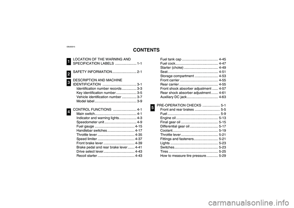
1-CONTENTS
LOCATION OF THE WARNING AND
SPECIFICATION LABELS ...................... 1-1
SAFETY INFORMATION ......................... 2-1
DESCRIPTION AND MACHINE
IDENTIFICATION ................................... 3-1
Identification number records ............... 3-3
Key identification number ..................... 3-5
Vehicle identification number ............... 3-7
Model label ........................................... 3-9
CONTROL FUNCTIONS ........................ 4-1
Main switch........................................... 4-1
Indicator and warning lights.................. 4-3
Speedometer unit ................................. 4-9
Fuel gauge ......................................... 4-15
Handlebar switches ............................ 4-17
Throttle lever ...................................... 4-35
Speed limiter ...................................... 4-37
Front brake lever ................................ 4-39
Brake pedal and rear brake lever ....... 4-41
Drive select lever ................................ 4-43
Recoil starter ...................................... 4-43
1234
Fuel tank cap ..................................... 4-45
Fuel cock............................................ 4-47
Starter (choke) ................................... 4-49
Seat.................................................... 4-51
Storage compartment ........................ 4-53
Front carrier ....................................... 4-55
Rear carrier ........................................ 4-55
Front shock absorber adjustment ...... 4-57
Rear shock absorber adjustment ....... 4-61
Auxiliary DC jack ................................ 4-63
PRE-OPERATION CHECKS .................. 5-1
Front and rear brakes .......................... 5-5
Fuel ...................................................... 5-9
Engine oil ........................................... 5-13
Final gear oil ...................................... 5-15
Differential gear oil ............................. 5-17
Coolant............................................... 5-19
Throttle lever ...................................... 5-21
Fittings and fasteners......................... 5-21
Lights ................................................. 5-23
Switches............................................. 5-23
Tires ................................................... 5-25
How to measure tire pressure ............ 5-29
5
U5ND61.book Page 1 Thursday, June 5, 2003 7:02 PM
Page 17 of 446
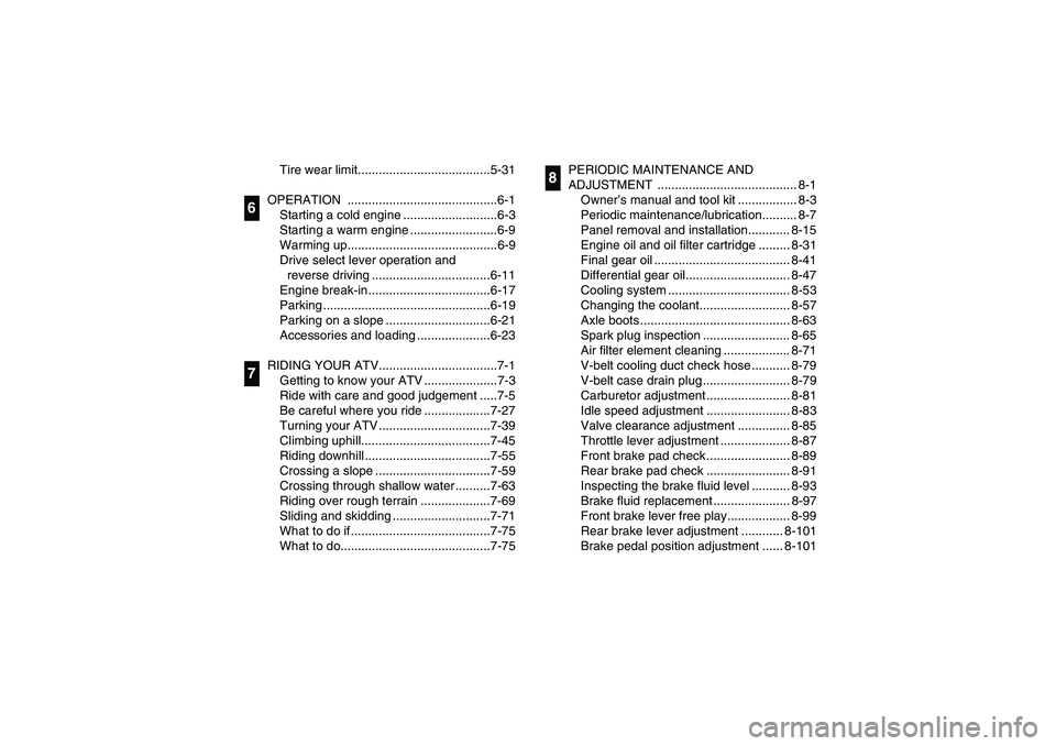
Tire wear limit......................................5-31
OPERATION ...........................................6-1
Starting a cold engine ...........................6-3
Starting a warm engine .........................6-9
Warming up...........................................6-9
Drive select lever operation and
reverse driving ..................................6-11
Engine break-in ...................................6-17
Parking ................................................6-19
Parking on a slope ..............................6-21
Accessories and loading .....................6-23
RIDING YOUR ATV..................................7-1
Getting to know your ATV .....................7-3
Ride with care and good judgement .....7-5
Be careful where you ride ...................7-27
Turning your ATV ................................7-39
Climbing uphill.....................................7-45
Riding downhill ....................................7-55
Crossing a slope .................................7-59
Crossing through shallow water ..........7-63
Riding over rough terrain ....................7-69
Sliding and skidding ............................7-71
What to do if ........................................7-75
What to do...........................................7-75
67
PERIODIC MAINTENANCE AND
ADJUSTMENT ........................................ 8-1
Owner’s manual and tool kit ................. 8-3
Periodic maintenance/lubrication.......... 8-7
Panel removal and installation............ 8-15
Engine oil and oil filter cartridge ......... 8-31
Final gear oil ....................................... 8-41
Differential gear oil.............................. 8-47
Cooling system ................................... 8-53
Changing the coolant.......................... 8-57
Axle boots ........................................... 8-63
Spark plug inspection ......................... 8-65
Air filter element cleaning ................... 8-71
V-belt cooling duct check hose ........... 8-79
V-belt case drain plug ......................... 8-79
Carburetor adjustment ........................ 8-81
Idle speed adjustment ........................ 8-83
Valve clearance adjustment ............... 8-85
Throttle lever adjustment .................... 8-87
Front brake pad check ........................ 8-89
Rear brake pad check ........................ 8-91
Inspecting the brake fluid level ........... 8-93
Brake fluid replacement ...................... 8-97
Front brake lever free play.................. 8-99
Rear brake lever adjustment ............ 8-101
Brake pedal position adjustment ...... 8-101
8
U5ND61.book Page 2 Thursday, June 5, 2003 7:02 PM
Page 56 of 446
3-1
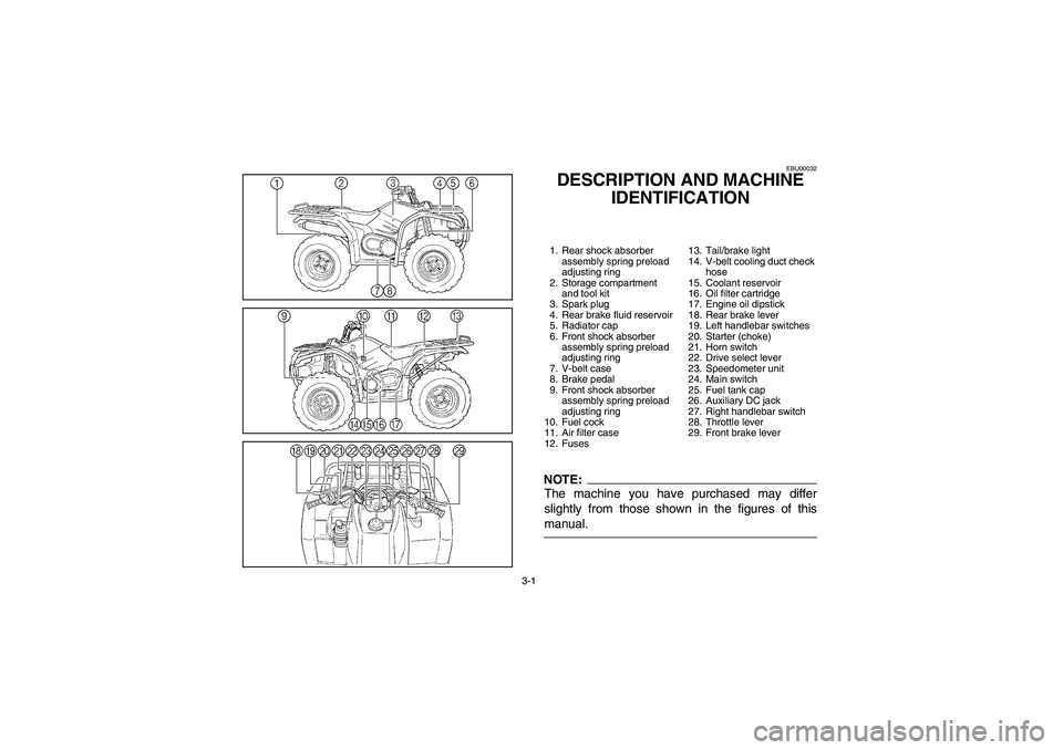
EBU00032
DESCRIPTION AND MACHINE
IDENTIFICATION1. Rear shock absorber
assembly spring preload
adjusting ring
2. Storage compartment
and tool kit
3. Spark plug
4. Rear brake fluid reservoir
5. Radiator cap
6. Front shock absorber
assembly spring preload
adjusting ring
7. V-belt case
8. Brake pedal
9. Front shock absorber
assembly spring preload
adjusting ring
10. Fuel cock
11. Air filter case
12. Fuses13. Tail/brake light
14. V-belt cooling duct check
hose
15. Coolant reservoir
16. Oil filter cartridge
17. Engine oil dipstick
18. Rear brake lever
19. Left handlebar switches
20. Starter (choke)
21. Horn switch
22. Drive select lever
23. Speedometer unit
24. Main switch
25. Fuel tank cap
26. Auxiliary DC jack
27. Right handlebar switch
28. Throttle lever
29. Front brake leverNOTE:The machine you have purchased may differ
slightly from those shown in the figures of this
manual.
U5ND61.book Page 1 Thursday, June 5, 2003 7:02 PM
Page 70 of 446

4-5 1. Differential gear lock indicator light “DIFF. LOCK”
2. Low-range indicator light “L”
3. High-range indicator light “H”4. Neutral indicator light “N”
5. Reverse indicator light “R”6. Park indicator light “P”
7. Differential gear lock indicator “”
8. Coolant temperature warning light “”
1. Témoin de blocage du différentiel “DIFF. LOCK”
2Témoin du rapport inférieur “L”
3. Témoin du rapport supérieur “H”4. Témoin de point mort “N”
5. Témoin de marche arrière “R”
6. Témoin de stationnement “P”
7. Indicateur de blocage du différentiel “”
8. Témoin d’avertissement de la température du liquide de
refroidissement “”
1. Luz indicadora de bloqueo del diferencial “DIFF. LOCK”
2 Luz indicadora de margen bajo “L”
3. Luz indicadora de margen alto “H”
4. Luz de control de punto muerto “N”
5. Luz de control de marcha atrás “R”
6. Luz indicadora de estacionamiento “P”
7. Indicadora de bloqueo del diferencial “”
8. Luz de aviso de la temperatura del refrigerante “”
DIFF.
LOCKDIFF.
LOCK
DIFF.
LOCK
EBU09720
Neutral indicator light “N”
This indicator light comes on when the drive select
lever is in the “N” position.
EBU12500
Reverse indicator light “R”
This indicator light comes on when the drive select
lever is in the “R” position.
EBU00609
Park indicator light “P”
This indicator light comes on when the drive select
lever is in the “P” (park) position.
EBU00860
Coolant temperature warning light “”
When the coolant temperature reaches a specified
level, this light comes on to warn that the coolant
temperature is too hot. If the light comes on during
operation, stop the engine as soon as it is safe to
do so and allow the engine to cool down for about
10 minutes.
U5ND61.book Page 5 Thursday, June 5, 2003 7:02 PM
Page 132 of 446
5-1
EBU00113
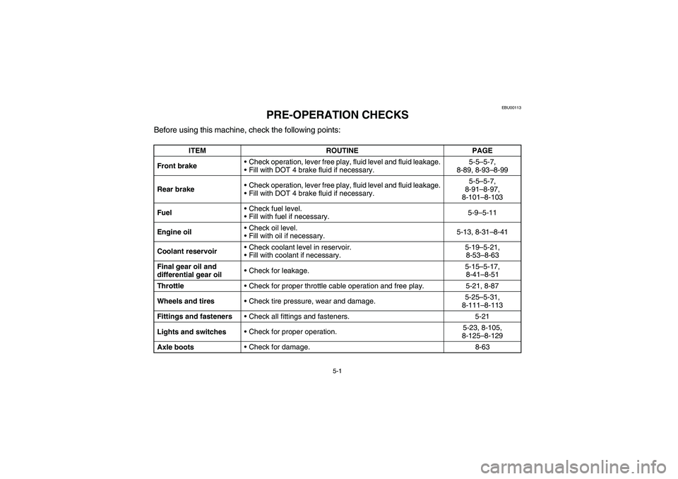
PRE-OPERATION CHECKS
Before using this machine, check the following points:
ITEM ROUTINE PAGE
Front brakeCheck operation, lever free play, fluid level and fluid leakage.
Fill with DOT 4 brake fluid if necessary.5-5–5-7,
8-89, 8-93–8-99
Rear brakeCheck operation, lever free play, fluid level and fluid leakage.
Fill with DOT 4 brake fluid if necessary.5-5–5-7,
8-91–8-97,
8-101–8-103
FuelCheck fuel level.
Fill with fuel if necessary.5-9–5-11
Engine oilCheck oil level.
Fill with oil if necessary.5-13, 8-31–8-41
Coolant reservoirCheck coolant level in reservoir.
Fill with coolant if necessary.5-19–5-21,
8-53–8-63
Final gear oil and
differential gear oilCheck for leakage.5-15–5-17,
8-41–8-51
ThrottleCheck for proper throttle cable operation and free play. 5-21, 8-87
Wheels and tiresCheck tire pressure, wear and damage.5-25–5-31,
8-111–8-113
Fittings and fastenersCheck all fittings and fasteners. 5-21
Lights and switchesCheck for proper operation.5-23, 8-105,
8-125–8-129
Axle bootsCheck for damage. 8-63
U5ND61.book Page 1 Thursday, June 5, 2003 7:02 PM
Page 150 of 446

5-19
EBU13160
Coolant
Check the coolant level in the coolant reservoir
when the engine is cold. (The coolant level will
vary with engine temperature.) The coolant level is
satisfactory if it is between the minimum and max-
imum level marks on the coolant reservoir. If the
coolant level is at or below the minimum level
mark, add distilled water to bring the level up to the
maximum level mark. Change the coolant every
two years. (See pages 8-53–8-63 for details.)CAUTION:_ Hard water or salt water is harmful to the en-
gine. You may use soft water if you cannot get
distilled water. _
Coolant reservoir capacity
(up to the maximum level mark):
0.25 L
U5ND61.book Page 19 Thursday, June 5, 2003 7:02 PM
Page 282 of 446
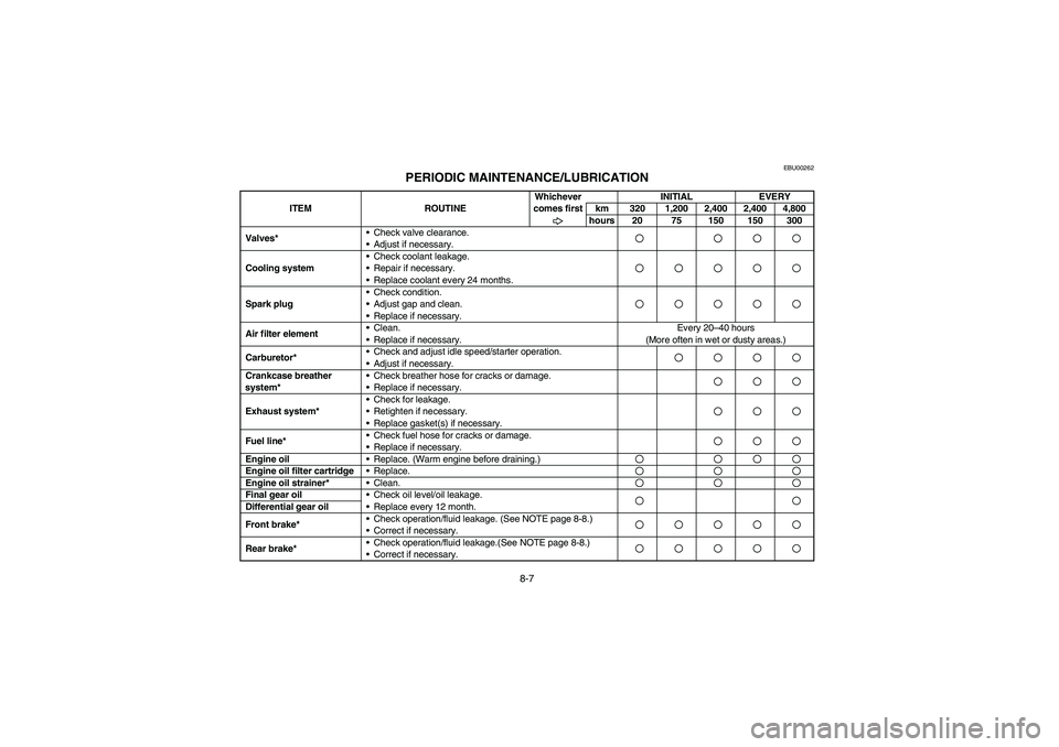
8-7
EBU00262
PERIODIC MAINTENANCE/LUBRICATION
ITEM ROUTINEWhichever
comes firstINITIAL EVERY
km 320 1,200 2,400 2,400 4,800
hours 20 75 150 150 300
Valves*Check valve clearance.
Adjust if necessary.
Cooling systemCheck coolant leakage.
Repair if necessary.
Replace coolant every 24 months.Spark plugCheck condition.
Adjust gap and clean.
Replace if necessary.Air filter elementClean.
Replace if necessary.Every 20–40 hours
(More often in wet or dusty areas.)
Carburetor*Check and adjust idle speed/starter operation.
Adjust if necessary.Crankcase breather
system*Check breather hose for cracks or damage.
Replace if necessary.Exhaust system*Check for leakage.
Retighten if necessary.
Replace gasket(s) if necessary.Fuel line*Check fuel hose for cracks or damage.
Replace if necessary.Engine oil
Replace. (Warm engine before draining.)Engine oil filter cartridge
Replace.Engine oil strainer*
Clean.Final gear oil
Check oil level/oil leakage.
Replace every 12 month.Differential gear oil
Front brake*Check operation/fluid leakage. (See NOTE page 8-8.)
Correct if necessary.Rear brake*Check operation/fluid leakage.(See NOTE page 8-8.)
Correct if necessary.U5ND61.book Page 7 Thursday, June 5, 2003 7:02 PM
Page 328 of 446

8-53 1. Coolant reservoir cap
2. Maximum level mark
3. Minimum level mark
1. Bouchon du vase d’expansion
2. Repère de niveau maximum
3. Repère de niveau minimum
1. Tapa del depósito de refrigerante
2. Marca de nivel máximo
3. Marca de nivel mínimo
EBU13210
Cooling system
1. Place the ATV on a level surface.
2. Check the coolant level in the coolant reser-
voir when the engine is cold as the coolant
level will vary with engine temperature.NOTE:_ The coolant level should be between the minimum
and maximum level marks. _3. If the coolant is at or below the minimum level
mark, remove panel D. (See pages 8-17–
8-19 for panel removal and installation proce-
dures.)
4. Remove the reservoir cap, add coolant to the
maximum level mark, install the reservoir
cap, and then install the panel.
U5ND61.book Page 53 Thursday, June 5, 2003 7:02 PM
Page 332 of 446

8-57 1. Coolant drain bolt
1. Boulon de vidange du liquide de refroidissement
1. Perno de drenaje del refrigerante
1. Trough
1. Feuille de papier repliée en forme de conduit
1. Pasante
EBU13221
Changing the coolant
WARNING
_ Wait for the engine and radiator to cool before
removing the radiator cap. You could be
burned by hot fluid and steam blown out under
pressure. Always put a thick rag over the cap
when opening. Allow any remaining pressure
to escape before completely removing the cap. _1. Place the ATV on a level surface.
2. Remove panels E and F. (See pages 8-27–
8-29 for panel removal and installation proce-
dures.)
3. Place a container under the engine, and then
remove the coolant drain bolt. (Use a trough
or a similar object as shown to prevent cool-
ant from spilling on the footrest.)
4. Remove the front carrier and panel C. (See
pages 8-21 and 8-25 for panel removal and
installation procedures.)
U5ND61.book Page 57 Thursday, June 5, 2003 7:02 PM
Page 336 of 446

8-61
CAUTION:_ Hard water or salt water is harmful to the en-
gine. You may use soft water if you cannot get
distilled water. _14. Start the engine and let it idle for several min-
utes. Stop the engine, and then check the
coolant level in the radiator. If it is low, add
more coolant until it reaches the top of the ra-
diator.
15. Check for coolant leakage.Recommended antifreeze:
High quality ethylene glycol antifreeze
containing corrosion inhibitors for
aluminum engines.
Antifreeze and water mixing ratio:
1:1
Total amount:
1.30 L
Coolant reservoir capacity
(up to the maximum level mark):
0.25 L
U5ND61.book Page 61 Thursday, June 5, 2003 7:02 PM