YAMAHA WR 250F 2001 Manuale duso (in Italian)
Manufacturer: YAMAHA, Model Year: 2001, Model line: WR 250F, Model: YAMAHA WR 250F 2001Pages: 686, PDF Dimensioni: 62.6 MB
Page 31 of 686

GEN
INFO
INFORMATIONS IMPORTANTES
WICHTIGE INFORMATIONEN
INFORMAZIONI IMPORTANTI
WICHTIGE INFORMATIO-
NEN
VORBEREITUNG FÜR AUSBAU
UND ZERLEGUNG
1. Vor dem Ausbau oder Zerle-
gen der Bauteile sämtlichen
Schmutz, Schlamm, Staub so-
wie andere Fremdkörper ent-
fernen.
Wenn das Motorrad mit einem
Hochdruckwascher gereinigt
wird, sind folgende Teile sorg-
fältig abzudecken.
lSchalldämpferende
lLuftfilter-Einlaßöffnung
lWasserpumpengehäuse-
loch unten
lVergaser-Beschleuniger-
pumpe
2. Nur geeignete Werkzeuge und
Reinigungsmittel verwenden.
Siehe unter “SPEZIALWERK-
ZEUGE”.
3. Beim Zerlegen zusammenge-
hörige Teile immer gemein-
sam ablegen. Dies gilt beson-
ders für Zahnräder, Zylinder,
Kolben und alle beweglichen
Teile, die miteinander arbei-
ten. Solche Baugruppen dür-
fen nur komplett wiederver-
wendet oder ausgetauscht
werden.
4. Alle ausgebauten Teile reini-
gen und in der Reihenfolge
des Ausbaus auf einer saube-
ren Unterlage ablegen. Dies
gewährleistet einen zügigen
und korrekten Zusammenbau.
5. Alle Teile von offenem Feuer
fernhalten.
INFORMATIONS IMPOR-
TANTES
PREPARATION POUR LA DEPOSE
ET DEMONTAGE
1. Eliminer soigneusement crasse,
boue, poussière et corps étrangers
avant la dépose et le démontage.
Avant de laver le véhicule à l’eau
pressurisée, recouvrir les parties
suivantes:
lExtrémité du silencieux
lOrifice d’admission du filtre à
air
lOrifice au fond du carter de la
pompe à eau
lPompe d’accélération du car-
burateur
2. Utiliser les outils et le matériel de
nettoyage correct. Se reporter à la
section “OUTILS SPECIAUX”.
3. Lors du démontage de la
machine, garder les pièces conne-
xes ensemble. Ils comprennent
les engrenages, cylindres, pistons
et autres pièces connexes qui se
sont “accouplées” par usure nor-
male. Les pièces connexes doi-
vent être réutilisées en un
ensemble ou changées.
4. Lors du démontage de la
machine, nettoyer toutes les piè-
ces et les mettre dans des pla-
teaux dans l’ordre du démontage.
Ceci diminuera le temps de
remontage et permettra d’être sûr
que toutes les pièces sont correc-
tement remontées.
5. Tenir éloigné du feu.
1 - 3
INFORMAZIONI IMPOR-
TANTI
PREPARATIVI PER LA RIMO-
ZIONE E IL DISASSEMBLAGGIO
1. Rimuovere tutto lo sporco, il
fango, la polvere e il materiale
estraneo prima della rimozione e
del disassemblaggio.
Durante il lavaggio del veicolo
con acqua ad alta pressione,
coprire le parti seguenti:
lEstremità del silenziatore
lForo di ingresso del filtro
dell’aria
lForo di alloggiamento della
pompa dell’acqua in basso
lPompa di circolazione del car-
buratore
2. Utilizzare utensili e strumenta-
zione per la pulizia adatti. Fare
riferimento al paragrafo “UTEN-
SILI SPECIALI”.
3. Nello smontaggio del veicolo,
non separare parti accoppiate. Ciò
comprende gli ingranaggi, i cilin-
dri, i pistoni e altri pezzi accop-
piati, che si sono adattati l’uno
all’altro attraverso la normale
usura. Le parti accoppiate vanno
riutilizzate come una sola unità o
sostituite.
4. Durante lo smontaggio del vei-
colo, pulire tutti i pezzi e posizio-
narli sui vassoi nell’ordine in cui
sono stati smontati. Ciò abbrevia i
tempi di rimontaggio e assicura
che tutti i pezzi siano reinstallati
correttamente.
5. Tenere lontano dal fuoco.
Page 32 of 686
1 - 4
GEN
INFO
IMPORTANT INFORMATION
EC132000
ALL REPLACEMENT PARTS
1. We recommend to use Yamaha genuine
parts for all replacements. Use oil and/or
grease recommended by Yamaha for
assembly and adjustment.
EC133000
GASKETS, OIL SEALS AND O-RINGS
1. All gaskets, oil seals, and O-rings should
be replaced when an engine is over-
hauled. All gasket surfaces, oil seal lips,
and O-rings must be cleaned.
2. Properly oil all mating parts and bearings
during reassembly. Apply grease to the
oil seal lips.
EC134000
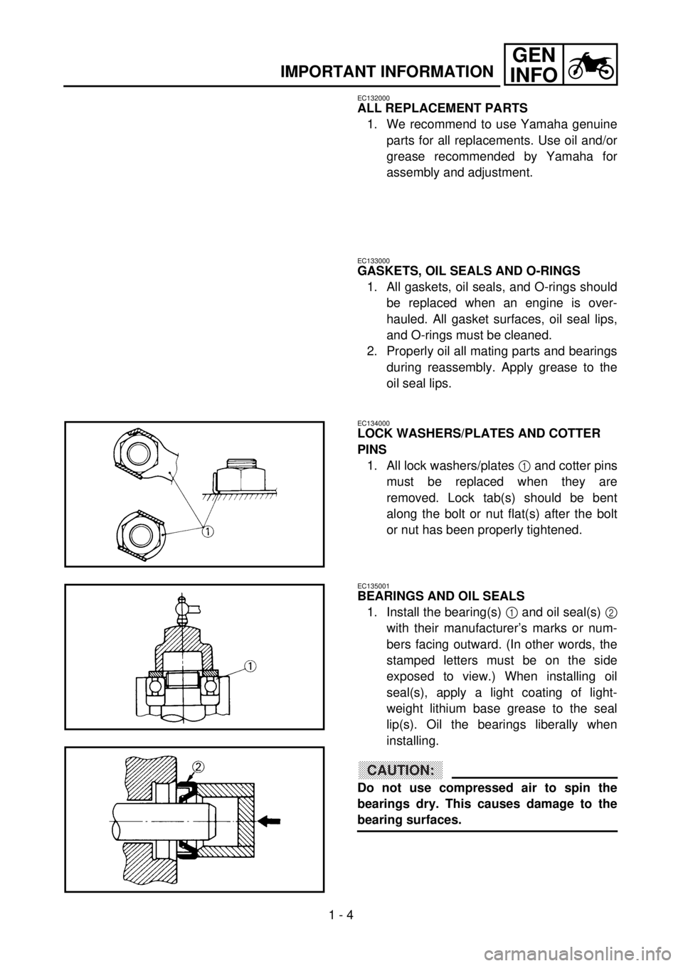
LOCK WASHERS/PLATES AND COTTER
PINS
1. All lock washers/plates
1
and cotter pins
must be replaced when they are
removed. Lock tab(s) should be bent
along the bolt or nut flat(s) after the bolt
or nut has been properly tightened.
EC135001
BEARINGS AND OIL SEALS
1. Install the bearing(s)
1 and oil seal(s) 2
with their manufacturer’s marks or num-
bers facing outward. (In other words, the
stamped letters must be on the side
exposed to view.) When installing oil
seal(s), apply a light coating of light-
weight lithium base grease to the seal
lip(s). Oil the bearings liberally when
installing.
CAUTION:
Do not use compressed air to spin the
bearings dry. This causes damage to the
bearing surfaces.
Page 33 of 686
GEN
INFO
INFORMATIONS IMPORTANTES
WICHTIGE INFORMATIONEN
INFORMAZIONI IMPORTANTI
ERSATZTEILE
1. Nur Original-Ersatzteile von
Yamaha verwenden. Nur von
Yamaha empfohlene Schmier-
stoffe verwenden. Fremdfabri-
kate erfüllen häufig nicht die
gestellten Qualitätsanforde-
rungen.
DICHTUNGEN, DICHTRINGE UND
O-RINGE
1. Beim Überholen des Motors
sind sämtliche Dichtungen,
Dichtringe und O-Ringe zu er-
neuern. Alle Dichtflächen,
Dichtlippen und O-Ringe vor
dem Zusammenbau säubern.
2. Beim Zusammenbau alle be-
weglichen Teile und Lager
ölen, alle Dichtlippen einfetten.
SICHERUNGSSCHEIBEN/ -BLE-
CHE UND SPLINTE
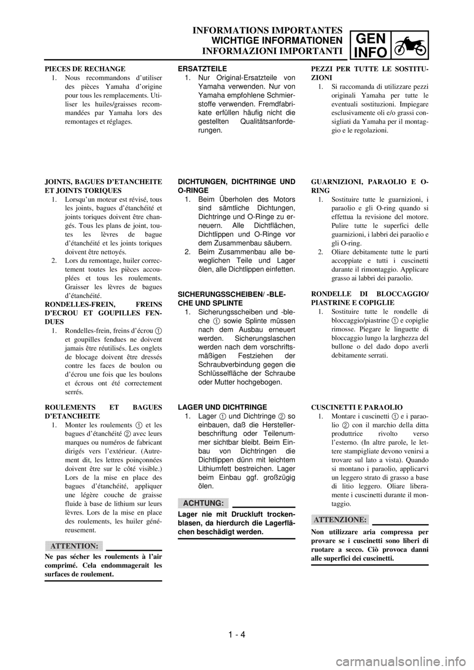
1. Sicherungsscheiben und -ble-
che 1 sowie Splinte müssen
nach dem Ausbau erneuert
werden. Sicherungslaschen
werden nach dem vorschrifts-
mäßigen Festziehen der
Schraubverbindung gegen die
Schlüsselfläche der Schraube
oder Mutter hochgebogen.
LAGER UND DICHTRINGE
1. Lager 1 und Dichtringe 2 so
einbauen, daß die Hersteller-
beschriftung oder Teilenum-
mer sichtbar bleibt. Beim Ein-
bau von Dichtringen die
Dichtlippen dünn mit leichtem
Lithiumfett bestreichen. Lager
beim Einbau ggf. großzügig
ölen.
ACHTUNG:
Lager nie mit Druckluft trocken-
blasen, da hierdurch die Lagerflä-
chen beschädigt werden. PIECES DE RECHANGE
1. Nous recommandons d’utiliser
des pièces Yamaha d’origine
pour tous les remplacements. Uti-
liser les huiles/graisses recom-
mandées par Yamaha lors des
remontages et réglages.
JOINTS, BAGUES D’ETANCHEITE
ET JOINTS TORIQUES
1. Lorsqu’un moteur est révisé, tous
les joints, bagues d’étanchéité et
joints toriques doivent être chan-
gés. Tous les plans de joint, tou-
tes les lèvres de bague
d’étanchéité et les joints toriques
doivent être nettoyés.
2. Lors du remontage, huiler correc-
tement toutes les pièces accou-
plées et tous les roulements.
Graisser les lèvres de bagues
d’étanchéité.
RONDELLES-FREIN, FREINS
D’ECROU ET GOUPILLES FEN-
DUES
1. Rondelles-frein, freins d’écrou 1
et goupilles fendues ne doivent
jamais être réutilisés. Les onglets
de blocage doivent être dressés
contre les faces de boulon ou
d’écrou une fois que les boulons
et écrous ont été correctement
serrés.
ROULEMENTS ET BAGUES
D’ETANCHEITE
1. Monter les roulements 1 et les
bagues d’étanchéité 2 avec leurs
marques ou numéros de fabricant
dirigés vers l’extérieur. (Autre-
ment dit, les lettres poinçonnées
doivent être sur le côté visible.)
Lors de la mise en place des
bagues d’étanchéité, appliquer
une légère couche de graisse
fluide à base de lithium sur leurs
lèvres. Lors de la mise en place
des roulements, les huiler géné-
reusement.
ATTENTION:
Ne pas sécher les roulements à l’air
comprimé. Cela endommagerait les
surfaces de roulement.
1 - 4
PEZZI PER TUTTE LE SOSTITU-
ZIONI
1. Si raccomanda di utilizzare pezzi
originali Yamaha per tutte le
eventuali sostituzioni. Impiegare
esclusivamente oli e/o grassi con-
sigliati da Yamaha per il montag-
gio e le regolazioni.
GUARNIZIONI, PARAOLIO E O-
RING
1. Sostituire tutte le guarnizioni, i
paraolio e gli O-ring quando si
effettua la revisione del motore.
Pulire tutte le superfici delle
guarnizioni, i labbri dei paraolio e
gli O-ring.
2. Oliare debitamente tutte le parti
accoppiate e tutti i cuscinetti
durante il rimontaggio. Applicare
grasso ai labbri dei paraolio.
RONDELLE DI BLOCCAGGIO/
PIASTRINE E COPIGLIE
1. Sostituire tutte le rondelle di
bloccaggio/piastrine 1 e copiglie
rimosse. Piegare le linguette di
bloccaggio lungo la larghezza del
bullone o del dado dopo averli
debitamente serrati.
CUSCINETTI E PARAOLIO
1. Montare i cuscinetti 1 e i parao-
lio 2 con il marchio della ditta
produttrice rivolto verso
l’esterno. (In altre parole, le let-
tere stampigliate devono venirsi a
trovare sul lato a vista). Quando
si montano i paraolio, applicarvi
un leggero strato di grasso a base
di litio leggero. Oliare libera-
mente i cuscinetti durante il mon-
taggio.
ATTENZIONE:
Non utilizzare aria compressa per
provare se i cuscinetti sono liberi di
ruotare a secco. Ciò provoca danni
alle superfici dei cuscinetti.
Page 34 of 686
1 - 5
GEN
INFO
IMPORTANT INFORMATION
EC136000
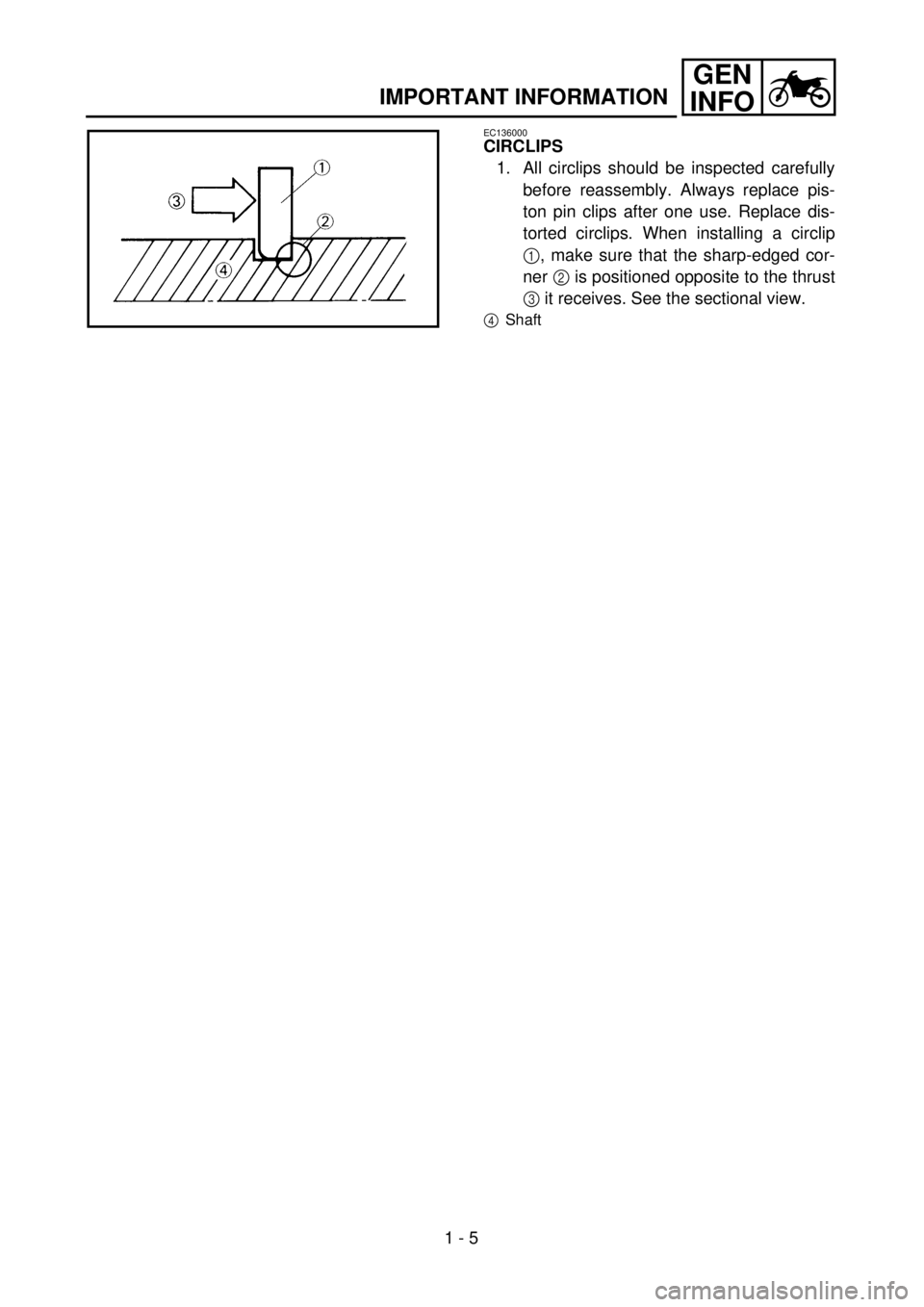
CIRCLIPS
1. All circlips should be inspected carefully
before reassembly. Always replace pis-
ton pin clips after one use. Replace dis-
torted circlips. When installing a circlip
1, make sure that the sharp-edged cor-
ner 2 is positioned opposite to the thrust
3 it receives. See the sectional view.
4Shaft
Page 35 of 686

GEN
INFO
INFORMATIONS IMPORTANTES
WICHTIGE INFORMATIONEN
INFORMAZIONI IMPORTANTI
SICHERUNGSRINGE
1. Sicherungsringe vor dem Wie-
dereinbau sorgfältig überprü-
fen und bei Beschädigung
oder Verformung erneuern.
Kolbenbolzensicherungen
müssen nach jedem Ausbau
erneuert werden. Beim Einbau
eines Sicherungsringes 1
stets darauf achten, daß die
scharfkantige Seite 2 den
Ring gegen die Druckrichtung
3 abstützt.
4
Welle
CIRCLIPS
1. Avant remontage, tous les circlips
doivent être soigneusement véri-
fiés. Toujours changer les circlips
d’axe de piston après une utilisa-
tion. Changer tout circlip
déformé. Lorsqu’on monte un cir-
clip 1, s’assurer que le côté non
chanfreiné 2 est positionné du
côté opposé à la poussée 3 qu’il
reçoit. Voir la vue en coupe.
4Arbre
1 - 5
ANELLI ELASTICI DI ARRESTO
1. Ispezionare attentamente tutti gli
anelli elastici di arresto prima di
rimontarli. Sostituire sempre gli
anelli elastici di arresto dello spi-
notto del pistone dopo averli uti-
lizzati una volta. Sostituire gli
anelli elastici di arresto defor-
mati. Quando si installa un anello
elastico di arresto, 1, accertarsi
che l’angolo dai bordi affilati 2
sia posizionato dal lato opposto a
quello da cui riceve 3 la spinta.
Si veda l’immagine in sezione.
4
Albero
Page 36 of 686
1 - 6
GEN
INFO
CHECKING OF CONNECTION
EC1C0001
CHECKING OF CONNECTION
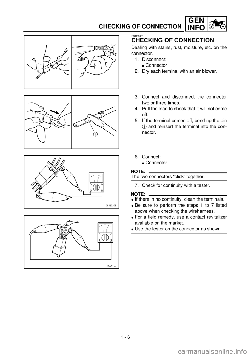
Dealing with stains, rust, moisture, etc. on the
connector.
1. Disconnect:
lConnector
2. Dry each terminal with an air blower.
3. Connect and disconnect the connector
two or three times.
4. Pull the lead to check that it will not come
off.
5. If the terminal comes off, bend up the pin
1 and reinsert the terminal into the con-
nector.
6. Connect:
lConnector
NOTE:
The two connectors “click” together.
7. Check for continuity with a tester.
NOTE:
lIf there in no continuity, clean the terminals.
lBe sure to perform the steps 1 to 7 listed
above when checking the wireharness.
lFor a field remedy, use a contact revitalizer
available on the market.
lUse the tester on the connector as shown.
Page 37 of 686
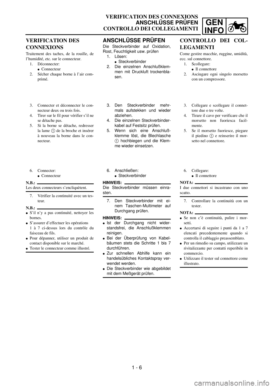
GEN
INFO
ANSCHLÜSSE PRÜFEN
Die Steckverbinder auf Oxidation,
Rost, Feuchtigkeit usw. prüfen
1. Lösen:
lSteckverbinder
2. Die einzelnen Anschlußklem-
men mit Druckluft trockenbla-
sen.
3. Den Steckverbinder mehr-
mals aufstekken und wieder
abziehen.
4. Die einzelnen Steckverbinder-
kabel auf Festsitz prüfen.
5. Wenn sich eine Anschluß-
klemme löst, die Blechlasche
1 hochbiegen und die Klem-
me wieder einsetzen.
6. Anschließen:
lSteckverbinder
HINWEIS:
Die Steckverbinder müssen einra-
sten.
7. Den Steckverbinder mit ei-
nem Taschen-Multimeter auf
Durchgang prüfen.
HINWEIS:
lIst der Durchgang nicht wider-
standsfrei, die Anschlußklemmen
reinigen.
lBei der Überprüfung von Kabel-
bäumen stets die Schritte 1 bis 7
durchführen.
lZur schnellen Abhilfe kann ein
handelsübliches Kontaktspray ver-
wendet werden.
lDie Steckverbinder wie abgebildet
mit dem Meßgerät prüfen.
VERIFICATION DES
CONNEXIONS
Traitement des taches, de la rouille, de
l’humidité, etc. sur le connecteur.
1. Déconnecter:
lConnecteur
2. Sécher chaque borne à l’air com-
primé.
3. Connecter et déconnecter le con-
necteur deux ou trois fois.
4. Tirer sur le fil pour vérifier s’il ne
se détache pas.
5. Si la borne se détache, redresser
la lame 1 de la broche et insérer
à nouveau la borne dans le con-
necteur.
6. Connecter:
lConnecteur
N.B.:
Les deux connecteurs s’encliquètent.
7. Vérifier la continuité avec un tes-
teur.
N.B.:
lS’il n’y a pas continuité, nettoyer les
bornes.
lS’assurer d’effectuer les opérations
1 à 7 ci-dessus lors du contrôle du
faisceau de fils.
lPour dépanner, utiliser un produit de
contact disponible sur le marché.
lTester le connecteur comme illustré.
CONTROLLO DEI COL-
LEGAMENTI
Come gestire macchie, ruggine, umidità,
ecc. sul connettore.
1. Scollegare:
lIl connettore
2. Asciugare ogni singolo morsetto
con un compressore.
3. Collegare e scollegare il connet-
tore due o tre volte.
4. Tirare il cavo per verificare che il
morsetto non fuoriesca facil-
mente.
5. Se il morsetto fuoriesce, piegare
il piedino 1 e reinserire il mor-
setto nel connettore.
6. Collegare:
lIl connettore
NOTA:
I due connettori si incastrano con uno
scatto.
7. Controllare la continuità con un
tester.
NOTA:
lSe non c’è continuità, pulire i mor-
setti.
lAccertarsi di seguire i punti da 1 a 7
elencati precedentemente quando si
controlla il cablaggio preassemblato.
lPer un rimedio su campo, utilizzare un
rivitalizzante per contatti reperibile in
commercio.
lUtilizzare il tester sul connettore come
illustrato.
VERIFICATION DES CONNEXIONS
ANSCHLÜSSE PRÜFEN
CONTROLLO DEI COLLEGAMENTI
1 - 6
Page 38 of 686

GEN
INFO
1 - 7
SPECIAL TOOLS
EC140001
SPECIAL TOOLS
The proper special tools are necessary for complete and accurate tune-up and assembly. Using the
correct special tool will help prevent damage caused by the use of improper tools or improvised
techniques. The shape and part number used for the special tool differ by country, so two types are
provided. Refer to the list provided to avoid errors when placing an order.
NOTE:
lFor U.S.A. and Canada, use part number starting with “YM-” or “YU-”.
lFor others, use part number starting with “90890-”.
Part number Tool name/How to use Illustration
YU-1135-A, 90890-01135 Crankcase separating tool
These tool is used to remove the crankshaft from
either case.YU-1135-A 90890-01135
YU-1235, 90890-01235 Rotor holding tool
This tool is used when loosening or tightening the fly-
wheel magneto securing nut.YU-1235 90890-01235
YU-3097, 90890-01252
YU-1256Dial gauge and stand
Stand
These tools are used to check each part for runout or
bent.YU-3097
YU-125690890-01252
YU-90050, 90890-01274
YU-90050, 90890-01275
YU-91044, 90890-04081
YM-1277, 90890-01277Crankshaft installing tool
Crankshaft installing pot
Crankshaft installing bolt
Spacer (crankshaft installer)
Adapter (M10)
These tools are used to install the crankshaft.YU-90050
YM-1277
YU-9104490890-01274
90890-01275
90890-01277
90890-04081
YU-1304, 90890-01304 Piston pin puller set
This tool is used to remove the piston pin.YU-1304 90890-01304
YU-24460-01, 90890-01325
YU-33984, 90890-01352Radiator cap tester
Radiator cap tester adapter
These tools are used for checking the cooling sys-
tem.YU-24460-01
YU-3398490890-01325
90890-01352
YU-33270-B, 90890-01362Flywheel puller
This tool is used to remove the flywheel magneto.YM-33270-B 90890-01362
Page 39 of 686
GEN
INFO
1 - 8
SPECIAL TOOLS
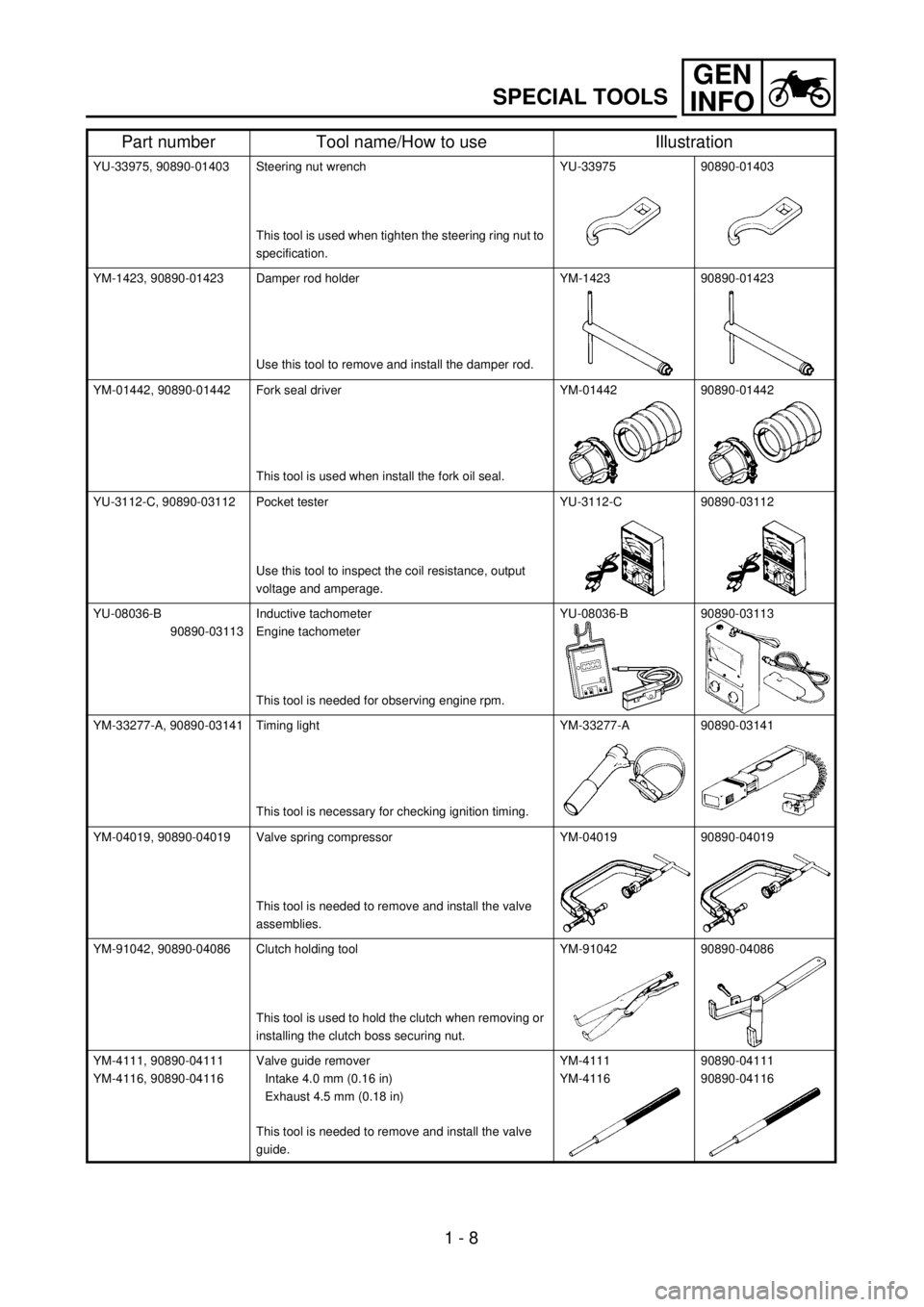
YU-33975, 90890-01403 Steering nut wrench
This tool is used when tighten the steering ring nut to
specification.YU-33975 90890-01403
YM-1423, 90890-01423 Damper rod holder
Use this tool to remove and install the damper rod.YM-1423 90890-01423
YM-01442, 90890-01442 Fork seal driver
This tool is used when install the fork oil seal.YM-01442 90890-01442
YU-3112-C, 90890-03112 Pocket tester
Use this tool to inspect the coil resistance, output
voltage and amperage.YU-3112-C 90890-03112
YU-08036-B
90890-03113Inductive tachometer
Engine tachometer
This tool is needed for observing engine rpm.YU-08036-B 90890-03113
YM-33277-A, 90890-03141 Timing light
This tool is necessary for checking ignition timing.YM-33277-A 90890-03141
YM-04019, 90890-04019 Valve spring compressor
This tool is needed to remove and install the valve
assemblies.YM-04019 90890-04019
YM-91042, 90890-04086 Clutch holding tool
This tool is used to hold the clutch when removing or
installing the clutch boss securing nut.YM-91042 90890-04086
YM-4111, 90890-04111
YM-4116, 90890-04116Valve guide remover
Intake 4.0 mm (0.16 in)
Exhaust 4.5 mm (0.18 in)
This tool is needed to remove and install the valve
guide.YM-4111
YM-411690890-04111
90890-04116
Part number Tool name/How to use Illustration
Page 40 of 686
GEN
INFO
1 - 9
SPECIAL TOOLS
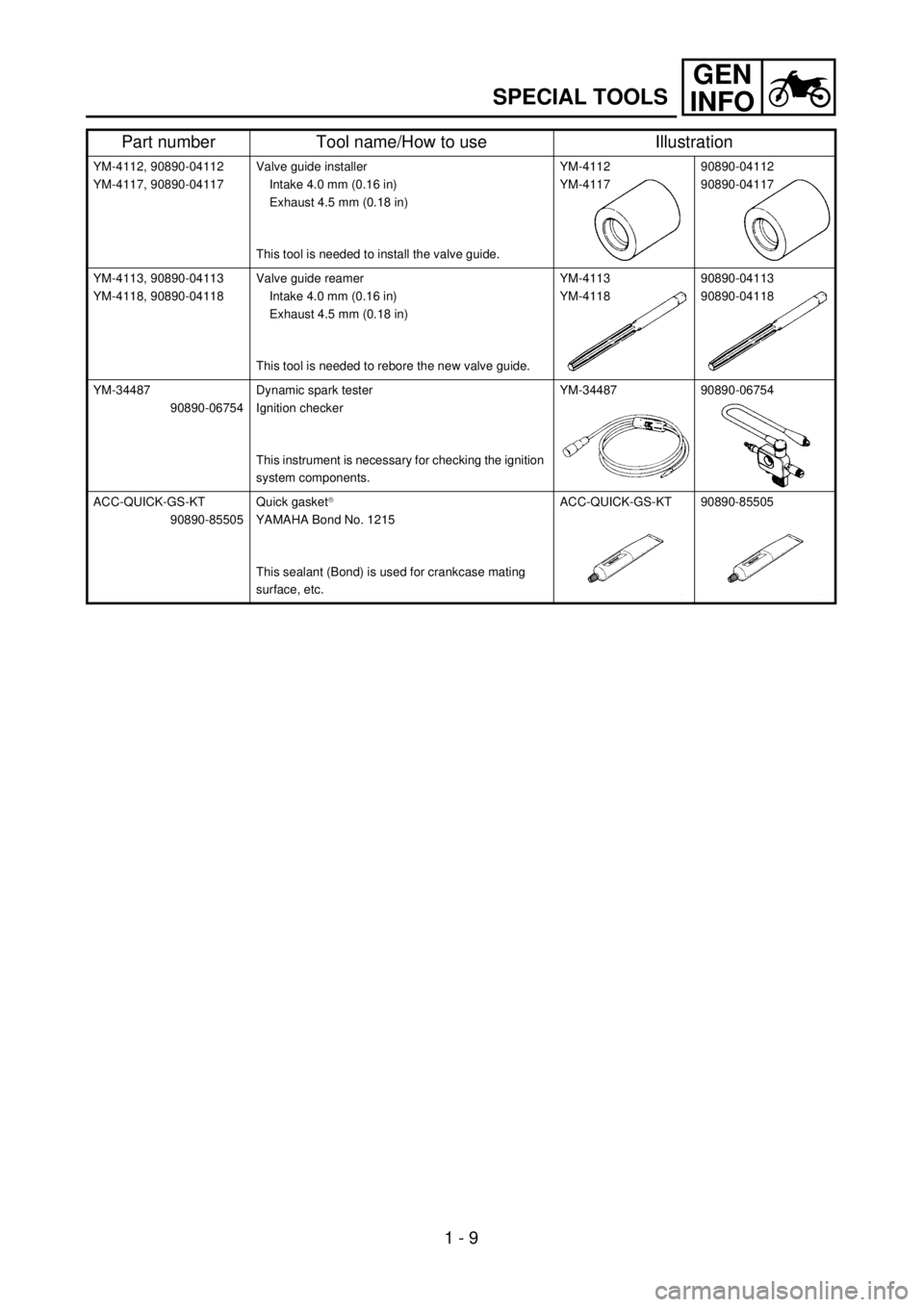
YM-4112, 90890-04112
YM-4117, 90890-04117Valve guide installer
Intake 4.0 mm (0.16 in)
Exhaust 4.5 mm (0.18 in)
This tool is needed to install the valve guide.YM-4112
YM-411790890-04112
90890-04117
YM-4113, 90890-04113
YM-4118, 90890-04118Valve guide reamer
Intake 4.0 mm (0.16 in)
Exhaust 4.5 mm (0.18 in)
This tool is needed to rebore the new valve guide.YM-4113
YM-411890890-04113
90890-04118
YM-34487
90890-06754Dynamic spark tester
Ignition checker
This instrument is necessary for checking the ignition
system components.YM-34487 90890-06754
ACC-QUICK-GS-KT
90890-85505Quick gasket
â
YAMAHA Bond No. 1215
This sealant (Bond) is used for crankcase mating
surface, etc.ACC-QUICK-GS-KT 90890-85505
Part number Tool name/How to use Illustration