YAMAHA WR 250F 2001 Owners Manual
Manufacturer: YAMAHA, Model Year: 2001, Model line: WR 250F, Model: YAMAHA WR 250F 2001Pages: 686, PDF Size: 62.6 MB
Page 211 of 686
INSP
ADJ
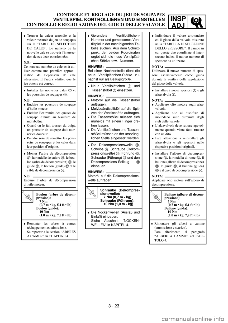
lGerundete Ventilplättchen-
Nummer und gemessenes Ven-
tilspiel in der nachfolgenden Ta-
belle suchen. Aus dem Schnitt-
punkt der beiden Koordinaten
ergibt sich die neue Ventilplätt-
chen-Stärke bzw. -Nummer.
HINWEIS:
Bei einer Nachkontrolle dient die
neue Ventilplättchen-Stärke zu-
nächst nur als Bezugsgröße.
lNeue Ventilplättchen 7 und
Tassenstößel 8 einsetzen.
HINWEIS:
lMotoröl auf die Tassenstößel
auftragen.
lMolybdändisulfidöl auf die Spit-
zen der Ventilschäfte auftragen.
lDie Tassenstößel müssen sich
mühelos mit einem Finger dre-
hen lassen.
lDie Ventilplättchen und Tassen-
stößel müssen an der ursprüng-
lichen Stelle eingesetzt werden.
lDie Dekompressionswelle 9,
Scheibe 0, Schraube (Dekom-
pressionswelle) A, Führung B,
Schraube (Führung) C und den
Dekompressions-Seilzug D
einbauen.
HINWEIS:
Motoröl auf die Dekompressions-
welle auftragen.
T R..
Schraube (Dekompres-
sionswelle):
7 Nm (0,7 m • kg)
Schraube (Führung):
10 Nm (1,0 m • kg)
lDie Nockenwellen (Auslaß und
Einlaß) einbauen.
Siehe Abschnitt “NOCKEN-
WELLEN” in KAPITEL 4.
lTrouver la valeur arrondie et la
valeur mesurée du jeu de soupapes
sur la “TABLE DE SELECTION
DE CALES”. Le numéro de la
nouvelle cale se trouve à l’intersec-
tion de ces deux coordonnées.
N.B.:
Ce nouveau numéro de cale est à uti-
liser comme une première approxi-
mation de l’épaisseur de cale
nécessaire. Il faudra vérifier que le
jeu obtenu est correct.
lInstaller les nouvelles cales 7 et
les poussoirs de soupapes 8.
N.B.:
lEnduire les poussoirs de soupape
d’huile moteur.
lEnduire l’extrémité des queues de
soupape d’huile au bisulfure de
molybdène.
lQuand on le fait tourner du doigt,
un poussoir de soupape doit tour-
ner en douceur.
lPrendre soin de remettre les pous-
soirs de soupapes et les cales dans
leur position d’origine.
lMonter l’arbre de décompression
9, la rondelle de cuivre 0, le bou-
lon (arbre de décompression) A, le
guide B, le boulon (guide) C et le
câble de décompression D.
N.B.:
Enduire l’arbre de décompression
d’huile moteur.
T R..
Boulon (arbre de décom-
pression):
7 Nm
(0,7 m • kg, 5,1 ft • lb)
Boulon (guide):
10 Nm
(1,0 m • kg, 7,2 ft • lb)
lRemonter les arbres à cames
(échappement et admission).
Se reporter à la section “ARBRES
A CAMES” au CHAPITRE 4.
lIndividuare il valore arrotondato
ed il gioco della valvola misurato
nella “TABELLA DI SELEZIONE
DELLO SPESSORE”. Il campo in
cui queste due coordinate si inter-
secano indica il nuovo numero di
spessore da utilizzare.
NOTA:
Utilizzare il nuovo numero di spes-
sore esclusivamente come guida
durante la verifica della regolazione
del gioco delle valvole.
lInstallare i nuovi spessori 7 e gli
alzavalvola 8.
NOTA:
lApplicare olio motore sugli alza-
valvola.
lApplicare olio al disolfuro di
molibdeno sulle estremità degli
steli delle valvole.
lL’alzavalvola deve ruotare agevol-
mente quando viene fatto ruotare
con un dito.
lFare attenzione a reinstallare gli
alzavalvola e gli spessori nelle
rispettive posizioni originali.
lInstallare l’albero di decompres-
sione 9, la rondella di rame 0, il
bullone (albero di decompressione)
A, le guide B, il bullone (guida)
C e il cavo di decompressione D.
NOTA:
Applicare olio motore sull’albero di
decompressione.
T R..
Bullone (albero di decom-
pressione):
7 Nm
(0,7 m • kg. 5,1 ft • lb)
Bullone (guida):
10 Nm
(1,0 m • kg. 7,2 ft • lb)
lRimontare gli alberi a camme
(ammissione e scarico).
Fare riferimento al paragrafo
“ALBERI A CAMME” nel CAPI-
TOLO 4.
3 - 23
CONTROLE ET REGLAGE DU JEU DE SOUPAPES
VENTILSPIEL KONTROLLIEREN UND EINSTELLEN
CONTROLLO E REGOLAZIONE DEL GIOCO DELLE VALVOLE
Page 212 of 686
3 - 24
INSP
ADJ
VALVE CLEARANCE INSPECTION AND ADJUSTMENT
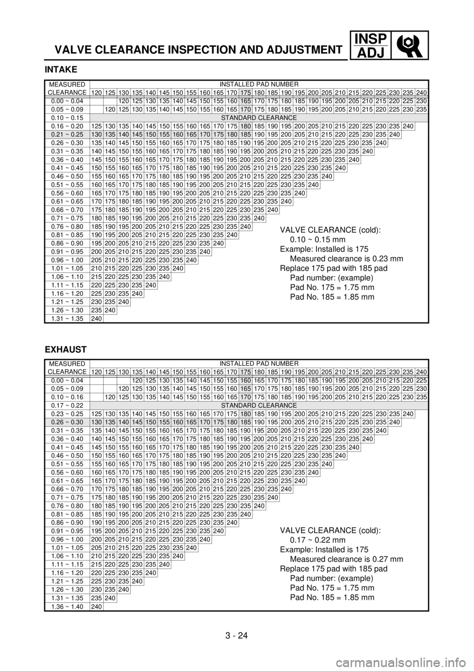
INTAKE
MEASURED
CLEARANCEINSTALLED PAD NUMBER
120 125 130 135 140 145 150 155 160 165 170
175 180 185 190 195 200 205 210 215 220 225 230 235 240
0.00 ~ 0.04 120 125 130 135 140 145 150 155
160165 170 175 180 185 190 195 200 205 210 215 220 225 230
0.05 ~ 0.09
120 125 130 135 140 145 150 155 160 165170 175 180 185 190 195 200 205 210 215 220 225 230 235
0.10 ~ 0.15
STANDARD CLEARANCE
0.16 ~ 0.20125130135140145150155160165170175180 185 190 195 200 205 210 215 220 225 230 235240
0.21 ~ 0.25130135140145150155160165170175180185 190 195 200 205 210 215 220 225 230 235240
0.26 ~ 0.30 135 140 145 150 155 160 165 170 175 180 185 190 195 200 205 210 215 220 225 230 235240
0.31 ~ 0.35 140 145 150 155 160 165 170 175 180 185 190 195 200 205 210 215 220 225 230 235240
0.36 ~ 0.40 145 150 155 160 165 170 175 180 185 190 195 200 205 210 215 220 225 230 235240
0.41 ~ 0.45 150 155 160 165 170 175 180 185 190 195 200 205 210 215 220 225 230 235240
0.46 ~ 0.50 155 160 165 170 175 180 185 190 195 200 205 210 215 220 225 230 235240
0.51 ~ 0.55 160 165 170 175 180 185 190 195 200 205 210 215 220 225 230 235240
0.56 ~ 0.60 165 170 175 180 185 190 195 200 205 210 215 220 225 230 235240
0.61 ~ 0.65 170 175 180 185 190 195 200 205 210 215 220 225 230 235240
0.66 ~ 0.70 175 180 185 190 195 200 205 210 215 220 225 230 235240
0.71 ~ 0.75 180 185 190 195 200 205 210 215 220 225 230 235240
0.76 ~ 0.80 185 190 195 200 205 210 215 220 225 230 235240VALVE CLEARANCE (cold):
0.10 ~ 0.15 mm
Example: Installed is 175
Measured clearance is 0.23 mm
Replace 175 pad with 185 pad
Pad number: (example)
Pad No. 175 = 1.75 mm
Pad No. 185 = 1.85 mm0.81 ~ 0.85 190 195 200 205 210 215 220 225 230 235240
0.86 ~ 0.90 195 200 205 210 215 220 225 230 235240
0.91 ~ 0.95 200 205 210 215 220 225 230 235240
0.96 ~ 1.00 205 210 215 220 225 230 235240
1.01 ~ 1.05 210 215 220 225 230 235240
1.06 ~ 1.10 215 220 225 230 235240
1.11 ~ 1.15 220 225 230 235240
1.16 ~ 1.20 225 230 235240
1.21 ~ 1.25 230 235240
1.26 ~ 1.30 235240
1.31 ~ 1.35 240
EXHAUST
MEASURED
CLEARANCEINSTALLED PAD NUMBER
120 125 130 135 140 145 150 155 160 165 170
175 180 185 190 195 200 205 210 215 220 225 230 235 240
0.00 ~ 0.04 120 125 130 135 140 145 150 155
160 165 170 175 180 185 190 195 200 205 210 215 220 225
0.05 ~ 0.09
120 125 130 135 140 145 150 155 160165 170 175 180 185 190 195 200 205 210 215 220 225 230
0.10 ~ 0.16
120125130135140145150155160165170 175 180 185 190 195 200 205 210 215 220 225230235
0.17 ~ 0.22STANDARD CLEARANCE
0.23 ~ 0.25 125 130 135 140 145 150 155 160 165 170 175
180 185 190 195 200 205 210 215 220 225230235 240
0.26 ~ 0.30130135140145150155160165170175180185 190 195 200 205 210 215 220 225230235240
0.31 ~ 0.35 135 140 145 150 155 160 165 170 175 180 185 190 195 200 205 210 215 220 225230235240
0.36 ~ 0.40 140 145 150 155 160 165 170 175 180 185 190 195 200 205 210 215 220 225230235240
0.41 ~ 0.45 145 150 155 160 165 170 175 180 185 190 195 200 205 210 215 220 225230235240
0.46 ~ 0.50 150 155 160 165 170 175 180 185 190 195 200 205 210 215 220 225230235240
0.51 ~ 0.55 155 160 165 170 175 180 185 190 195 200 205 210 215 220 225230235240
0.56 ~ 0.60 160 165 170 175 180 185 190 195 200 205 210 215 220 225230235240
0.61 ~ 0.65 165 170 175 180 185 190 195 200 205 210 215 220 225230235240
0.66 ~ 0.70 170 175 180 185 190 195 200 205 210 215 220 225230235240
0.71 ~ 0.75 175 180 185 190 195 200 205 210 215 220 225230235240
0.76 ~ 0.80 180 185 190 195 200 205 210 215 220 225230235240
0.81 ~ 0.85 185 190 195 200 205 210 215 220 225230235240
0.86 ~ 0.90 190 195 200 205 210 215 220 225230235240
VALVE CLEARANCE (cold):
0.17 ~ 0.22 mm
Example: Installed is 175
Measured clearance is 0.27 mm
Replace 175 pad with 185 pad
Pad number: (example)
Pad No. 175 = 1.75 mm
Pad No. 185 = 1.85 mm0.91 ~ 0.95 195 200 205 210 215 220 225230235240
0.96 ~ 1.00 200 205 210 215 220 225230235240
1.01 ~ 1.05 205 210 215 220 225230235240
1.06 ~ 1.10 210 215 220 225230235240
1.11 ~ 1.15 215 220 225230235240
1.16 ~ 1.20 220 225230235240
1.21 ~ 1.25 225230235240
1.26 ~ 1.30 230235240
1.31 ~ 1.35 235240
1.36 ~ 1.40 240
Page 213 of 686
INSP
ADJ
CONTROLE ET REGLAGE DU JEU DE SOUPAPES
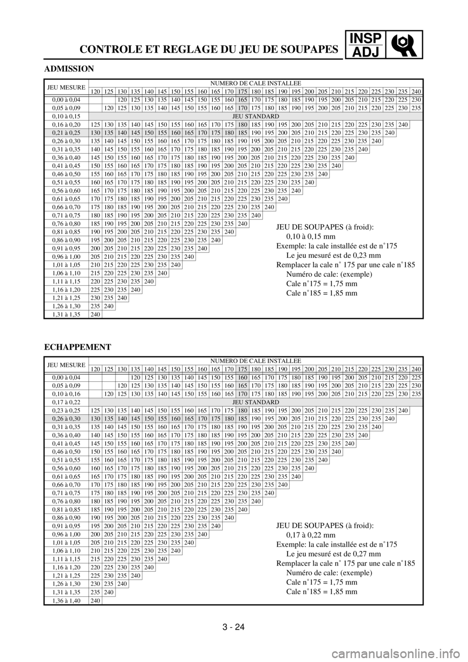
ADMISSION
JEU MESURENUMERO DE CALE INSTALLEE
120 125 130 135 140 145 150 155 160 165 170175 180 185 190 195 200 205 210 215 220 225 230 235 240
0,00 à 0,04 120 125 130 135 140 145 150 155
160165 170 175 180 185 190 195 200 205 210 215 220 225 230
0,05 à 0,09
120 125 130 135 140 145 150 155 160 165170 175 180 185 190 195 200 205 210 215 220 225 230 235
0,10 à 0,15
JEU STANDARD
0,16 à 0,20125130135140145150155160165170175180 185 190 195 200 205 210 215 220 225 230 235240
0,21 à 0,25130135140145150155160165170175180185 190 195 200 205 210 215 220 225 230 235240
0,26 à 0,30 135 140 145 150 155 160 165 170 175 180 185 190 195 200 205 210 215 220 225 230 235240
0,31 à 0,35 140 145 150 155 160 165 170 175 180 185 190 195 200 205 210 215 220 225 230 235240
0,36 à 0,40 145 150 155 160 165 170 175 180 185 190 195 200 205 210 215 220 225 230 235240
0,41 à 0,45 150 155 160 165 170 175 180 185 190 195 200 205 210 215 220 225 230 235240
0,46 à 0,50 155 160 165 170 175 180 185 190 195 200 205 210 215 220 225 230 235240
0,51 à 0,55 160 165 170 175 180 185 190 195 200 205 210 215 220 225 230 235240
0,56 à 0,60 165 170 175 180 185 190 195 200 205 210 215 220 225 230 235240
0,61 à 0,65 170 175 180 185 190 195 200 205 210 215 220 225 230 235240
0,66 à 0,70 175 180 185 190 195 200 205 210 215 220 225 230 235240
0,71 à 0,75 180 185 190 195 200 205 210 215 220 225 230 235240
0,76 à 0,80 185 190 195 200 205 210 215 220 225 230 235240JEU DE SOUPAPES (à froid):
0,10 à 0,15 mm
Exemple: la cale installée est de n˚175
Le jeu mesuré est de 0,23 mm
Remplacer la cale n˚ 175 par une cale n˚185
Numéro de cale: (exemple)
Cale n˚175 = 1,75 mm
Cale n˚185 = 1,85 mm0,81 à 0,85 190 195 200 205 210 215 220 225 230 235240
0,86 à 0,90 195 200 205 210 215 220 225 230 235240
0,91 à 0,95 200 205 210 215 220 225 230 235240
0,96 à 1,00 205 210 215 220 225 230 235240
1,01 à 1,05 210 215 220 225 230 235240
1,06 à 1,10 215 220 225 230 235240
1,11 à 1,15 220 225 230 235240
1,16 à 1,20 225 230 235240
1,21 à 1,25 230 235240
1,26 à 1,30 235240
1,31 à 1,35 240
ECHAPPEMENT
JEU MESURENUMERO DE CALE INSTALLEE
120 125 130 135 140 145 150 155 160 165 170175 180 185 190 195 200 205 210 215 220 225 230 235 240
0,00 à 0,04 120 125 130 135 140 145 150 155
160 165 170 175 180 185 190 195 200 205 210 215 220 225
0,05 à 0,09
120 125 130 135 140 145 150 155 160165 170 175 180 185 190 195 200 205 210 215 220 225 230
0,10 à 0,16
120125130135140145150155160165170 175 180 185 190 195 200 205 210 215 220 225230235
0,17 à 0,22JEU STANDARD
0,23 à 0,25 125 130 135 140 145 150 155 160 165 170 175
180 185 190 195 200 205 210 215 220 225230235 240
0,26 à 0,30130135140145150155160165170175180185 190 195 200 205 210 215 220 225230235240
0,31 à 0,35 135 140 145 150 155 160 165 170 175 180 185 190 195 200 205 210 215 220 225230235240
0,36 à 0,40 140 145 150 155 160 165 170 175 180 185 190 195 200 205 210 215 220 225230235240
0,41 à 0,45 145 150 155 160 165 170 175 180 185 190 195 200 205 210 215 220 225230235240
0,46 à 0,50 150 155 160 165 170 175 180 185 190 195 200 205 210 215 220 225230235240
0,51 à 0,55 155 160 165 170 175 180 185 190 195 200 205 210 215 220 225230235240
0,56 à 0,60 160 165 170 175 180 185 190 195 200 205 210 215 220 225230235240
0,61 à 0,65 165 170 175 180 185 190 195 200 205 210 215 220 225230235240
0,66 à 0,70 170 175 180 185 190 195 200 205 210 215 220 225230235240
0,71 à 0,75 175 180 185 190 195 200 205 210 215 220 225230235240
0,76 à 0,80 180 185 190 195 200 205 210 215 220 225230235240
0,81 à 0,85 185 190 195 200 205 210 215 220 225230235240
0,86 à 0,90 190 195 200 205 210 215 220 225230235240
JEU DE SOUPAPES (à froid):
0,17 à 0,22 mm
Exemple: la cale installée est de n˚175
Le jeu mesuré est de 0,27 mm
Remplacer la cale n˚ 175 par une cale n˚185
Numéro de cale: (exemple)
Cale n˚175 = 1,75 mm
Cale n˚185 = 1,85 mm0,91 à 0,95 195 200 205 210 215 220 225230235240
0,96 à 1,00 200 205 210 215 220 225230235240
1,01 à 1,05 205 210 215 220 225230235240
1,06 à 1,10 210 215 220 225230235240
1,11 à 1,15 215 220 225230235240
1,16 à 1,20 220 225230235240
1,21 à 1,25 225230235240
1,26 à 1,30 230235240
1,31 à 1,35 235240
1,36 à 1,40 240
3 - 24
Page 214 of 686
INSP
ADJ
VENTILSPIEL KONTROLLIEREN UND EINSTELLEN
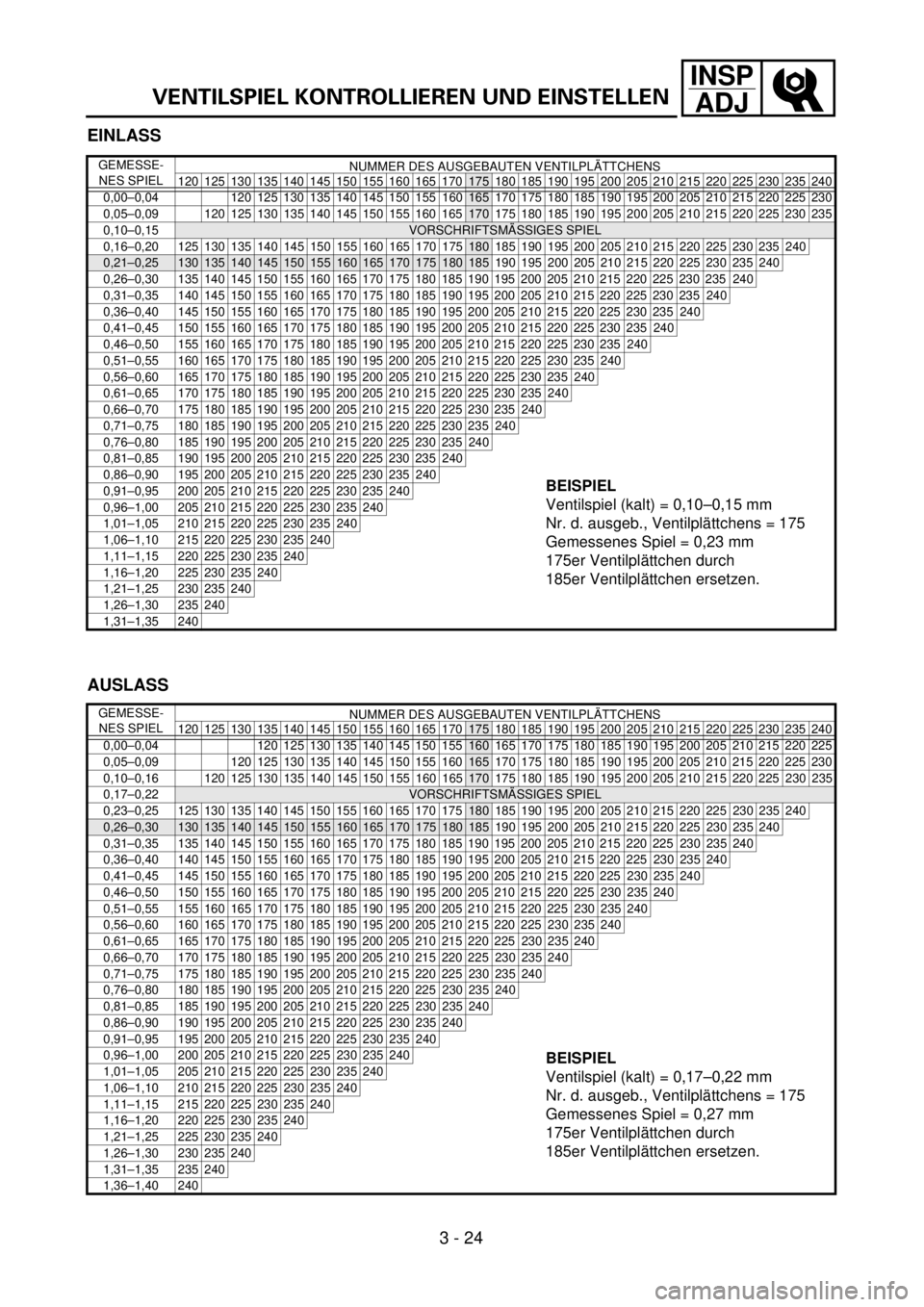
EINLASS
GEMESSE-
NES SPIELNUMMER DES AUSGEBAUTEN VENTILPLÄTTCHENS
120 125 130 135 140 145 150 155 160 165 170
175 180 185 190 195 200 205 210 215 220 225 230 235 240
0,00–0,04 120 125 130 135 140 145 150 155
160165 170 175 180 185 190 195 200 205 210 215 220 225 230
0,05–0,09
120 125 130 135 140 145 150 155 160 165170 175 180 185 190 195 200 205 210 215 220 225 230 235
0,10–0,15
VORSCHRIFTSMÄSSIGES SPIEL
0,16–0,20125130135140145150155160165170175180 185 190 195 200 205 210 215 220 225 230 235240
0,21–0,25130135140145150155160165170175180185 190 195 200 205 210 215 220 225 230 235240
0,26–0,30 135 140 145 150 155 160 165 170 175 180 185 190 195 200 205 210 215 220 225 230 235240
0,31–0,35 140 145 150 155 160 165 170 175 180 185 190 195 200 205 210 215 220 225 230 235240
0,36–0,40 145 150 155 160 165 170 175 180 185 190 195 200 205 210 215 220 225 230 235240
0,41–0,45 150 155 160 165 170 175 180 185 190 195 200 205 210 215 220 225 230 235240
0,46–0,50 155 160 165 170 175 180 185 190 195 200 205 210 215 220 225 230 235240
0,51–0,55 160 165 170 175 180 185 190 195 200 205 210 215 220 225 230 235240
0,56–0,60 165 170 175 180 185 190 195 200 205 210 215 220 225 230 235240
0,61–0,65 170 175 180 185 190 195 200 205 210 215 220 225 230 235240
0,66–0,70 175 180 185 190 195 200 205 210 215 220 225 230 235240
0,71–0,75 180 185 190 195 200 205 210 215 220 225 230 235240
0,76–0,80 185 190 195 200 205 210 215 220 225 230 235240
BEISPIEL
Ventilspiel (kalt) = 0,10–0,15 mm
Nr. d. ausgeb., Ventilplättchens = 175
Gemessenes Spiel = 0,23 mm
175er Ventilplättchen durch
185er Ventilplättchen ersetzen.
0,81–0,85 190 195 200 205 210 215 220 225 230 235240
0,86–0,90 195 200 205 210 215 220 225 230 235240
0,91–0,95 200 205 210 215 220 225 230 235240
0,96–1,00 205 210 215 220 225 230 235240
1,01–1,05 210 215 220 225 230 235240
1,06–1,10 215 220 225 230 235240
1,11–1,15 220 225 230 235240
1,16–1,20 225 230 235240
1,21–1,25 230 235240
1,26–1,30 235240
1,31–1,35 240
AUSLASS
GEMESSE-
NES SPIELNUMMER DES AUSGEBAUTEN VENTILPLÄTTCHENS
120 125 130 135 140 145 150 155 160 165 170
175 180 185 190 195 200 205 210 215 220 225 230 235 240
0,00–0,04 120 125 130 135 140 145 150 155
160 165 170 175 180 185 190 195 200 205 210 215 220 225
0,05–0,09
120 125 130 135 140 145 150 155 160165 170 175 180 185 190 195 200 205 210 215 220 225 230
0,10–0,16
120125130135140145150155160165170 175 180 185 190 195 200 205 210 215 220 225230235
0,17–0,22VORSCHRIFTSMÄSSIGES SPIEL
0,23–0,25 125 130 135 140 145 150 155 160 165 170 175
180 185 190 195 200 205 210 215 220 225230235 240
0,26–0,30130135140145150155160165170175180185 190 195 200 205 210 215 220 225230235240
0,31–0,35 135 140 145 150 155 160 165 170 175 180 185 190 195 200 205 210 215 220 225230235240
0,36–0,40 140 145 150 155 160 165 170 175 180 185 190 195 200 205 210 215 220 225230235240
0,41–0,45 145 150 155 160 165 170 175 180 185 190 195 200 205 210 215 220 225230235240
0,46–0,50 150 155 160 165 170 175 180 185 190 195 200 205 210 215 220 225230235240
0,51–0,55 155 160 165 170 175 180 185 190 195 200 205 210 215 220 225230235240
0,56–0,60 160 165 170 175 180 185 190 195 200 205 210 215 220 225230235240
0,61–0,65 165 170 175 180 185 190 195 200 205 210 215 220 225230235240
0,66–0,70 170 175 180 185 190 195 200 205 210 215 220 225230235240
0,71–0,75 175 180 185 190 195 200 205 210 215 220 225230235240
0,76–0,80 180 185 190 195 200 205 210 215 220 225230235240
0,81–0,85 185 190 195 200 205 210 215 220 225230235240
0,86–0,90 190 195 200 205 210 215 220 225230235240
BEISPIEL
Ventilspiel (kalt) = 0,17–0,22 mm
Nr. d. ausgeb., Ventilplättchens = 175
Gemessenes Spiel = 0,27 mm
175er Ventilplättchen durch
185er Ventilplättchen ersetzen.
0,91–0,95 195 200 205 210 215 220 225230235240
0,96–1,00 200 205 210 215 220 225230235240
1,01–1,05 205 210 215 220 225230235240
1,06–1,10 210 215 220 225230235240
1,11–1,15 215 220 225230235240
1,16–1,20 220 225230235240
1,21–1,25 225230235240
1,26–1,30 230235240
1,31–1,35 235240
1,36–1,40 240
3 - 24
Page 215 of 686
INSP
ADJCONTROLLO E REGOLAZIONE DEL GIOCO DELLE
VALVOLE
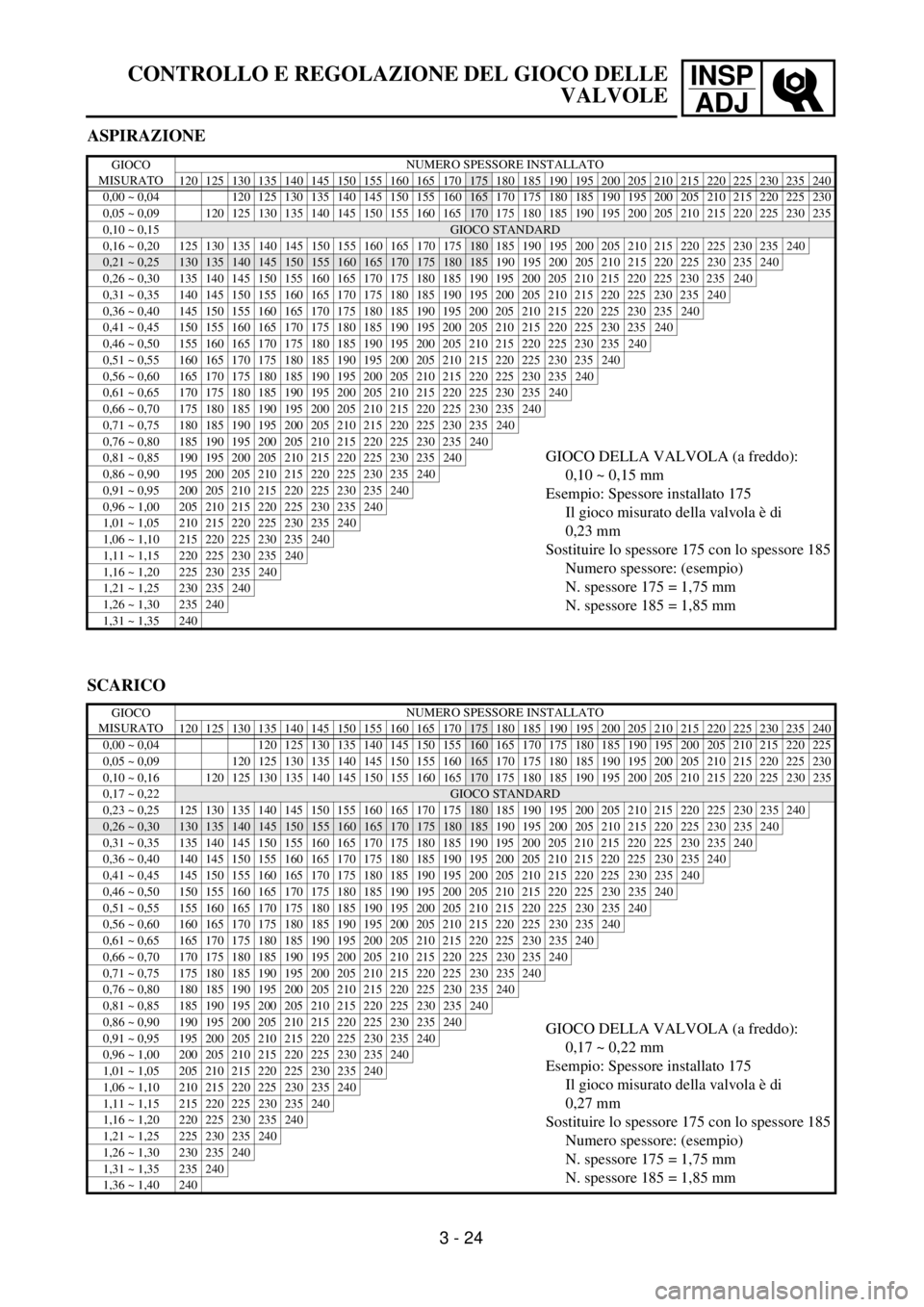
ASPIRAZIONE
GIOCO
MISURATONUMERO SPESSORE INSTALLATO
120 125 130 135 140 145 150 155 160 165 170
175 180 185 190 195 200 205 210 215 220 225 230 235 240
0,00 ~ 0,04 120 125 130 135 140 145 150 155
160165 170 175 180 185 190 195 200 205 210 215 220 225 230
0,05 ~ 0,09
120 125 130 135 140 145 150 155 160 165170 175 180 185 190 195 200 205 210 215 220 225 230 235
0,10 ~ 0,15
GIOCO STANDARD
0,16 ~ 0,20125130135140145150155160165170175180 185 190 195 200 205 210 215 220 225 230 235240
0,21 ~ 0,25130135140145150155160165170175180185 190 195 200 205 210 215 220 225 230 235240
0,26 ~ 0,30 135 140 145 150 155 160 165 170 175 180 185 190 195 200 205 210 215 220 225 230 235240
0,31 ~ 0,35 140 145 150 155 160 165 170 175 180 185 190 195 200 205 210 215 220 225 230 235240
0,36 ~ 0,40 145 150 155 160 165 170 175 180 185 190 195 200 205 210 215 220 225 230 235240
0,41 ~ 0,45 150 155 160 165 170 175 180 185 190 195 200 205 210 215 220 225 230 235240
0,46 ~ 0,50 155 160 165 170 175 180 185 190 195 200 205 210 215 220 225 230 235240
0,51 ~ 0,55 160 165 170 175 180 185 190 195 200 205 210 215 220 225 230 235240
0,56 ~ 0,60 165 170 175 180 185 190 195 200 205 210 215 220 225 230 235240
0,61 ~ 0,65 170 175 180 185 190 195 200 205 210 215 220 225 230 235240
0,66 ~ 0,70 175 180 185 190 195 200 205 210 215 220 225 230 235240
0,71 ~ 0,75 180 185 190 195 200 205 210 215 220 225 230 235240
0,76 ~ 0,80 185 190 195 200 205 210 215 220 225 230 235240
GIOCO DELLA VALVOLA (a freddo):
0,10 ~ 0,15 mm
Esempio: Spessore installato 175
Il gioco misurato della valvola è di
0,23 mm
Sostituire lo spessore 175 con lo spessore 185
Numero spessore: (esempio)
N. spessore 175 = 1,75 mm
N. spessore 185 = 1,85 mm0,81 ~ 0,85 190 195 200 205 210 215 220 225 230 235240
0,86 ~ 0,90 195 200 205 210 215 220 225 230 235240
0,91 ~ 0,95 200 205 210 215 220 225 230 235240
0,96 ~ 1,00 205 210 215 220 225 230 235240
1,01 ~ 1,05 210 215 220 225 230 235240
1,06 ~ 1,10 215 220 225 230 235240
1,11 ~ 1,15 220 225 230 235240
1,16 ~ 1,20 225 230 235240
1,21 ~ 1,25 230 235240
1,26 ~ 1,30 235240
1,31 ~ 1,35 240
SCARICO
GIOCO
MISURATONUMERO SPESSORE INSTALLATO
120 125 130 135 140 145 150 155 160 165 170
175 180 185 190 195 200 205 210 215 220 225 230 235 240
0,00 ~ 0,04 120 125 130 135 140 145 150 155
160 165 170 175 180 185 190 195 200 205 210 215 220 225
0,05 ~ 0,09
120 125 130 135 140 145 150 155 160165 170 175 180 185 190 195 200 205 210 215 220 225 230
0,10 ~ 0,16
120125130135140145150155160165170 175 180 185 190 195 200 205 210 215 220 225230235
0,17 ~ 0,22GIOCO STANDARD
0,23 ~ 0,25 125 130 135 140 145 150 155 160 165 170 175
180 185 190 195 200 205 210 215 220 225230235 240
0,26 ~ 0,30130135140145150155160165170175180185 190 195 200 205 210 215 220 225230235240
0,31 ~ 0,35 135 140 145 150 155 160 165 170 175 180 185 190 195 200 205 210 215 220 225230235240
0,36 ~ 0,40 140 145 150 155 160 165 170 175 180 185 190 195 200 205 210 215 220 225230235240
0,41 ~ 0,45 145 150 155 160 165 170 175 180 185 190 195 200 205 210 215 220 225230235240
0,46 ~ 0,50 150 155 160 165 170 175 180 185 190 195 200 205 210 215 220 225230235240
0,51 ~ 0,55 155 160 165 170 175 180 185 190 195 200 205 210 215 220 225230235240
0,56 ~ 0,60 160 165 170 175 180 185 190 195 200 205 210 215 220 225230235240
0,61 ~ 0,65 165 170 175 180 185 190 195 200 205 210 215 220 225230235240
0,66 ~ 0,70 170 175 180 185 190 195 200 205 210 215 220 225230235240
0,71 ~ 0,75 175 180 185 190 195 200 205 210 215 220 225230235240
0,76 ~ 0,80 180 185 190 195 200 205 210 215 220 225230235240
0,81 ~ 0,85 185 190 195 200 205 210 215 220 225230235240
0,86 ~ 0,90 190 195 200 205 210 215 220 225230235240GIOCO DELLA VALVOLA (a freddo):
0,17 ~ 0,22 mm
Esempio: Spessore installato 175
Il gioco misurato della valvola è di
0,27 mm
Sostituire lo spessore 175 con lo spessore 185
Numero spessore: (esempio)
N. spessore 175 = 1,75 mm
N. spessore 185 = 1,85 mm0,91 ~ 0,95 195 200 205 210 215 220 225230235240
0,96 ~ 1,00 200 205 210 215 220 225230235240
1,01 ~ 1,05 205 210 215 220 225230235240
1,06 ~ 1,10 210 215 220 225230235240
1,11 ~ 1,15 215 220 225230235240
1,16 ~ 1,20 220 225230235240
1,21 ~ 1,25 225230235240
1,26 ~ 1,30 230235240
1,31 ~ 1,35 235240
1,36 ~ 1,40 240
3 - 24
Page 216 of 686
3 - 25
INSP
ADJ
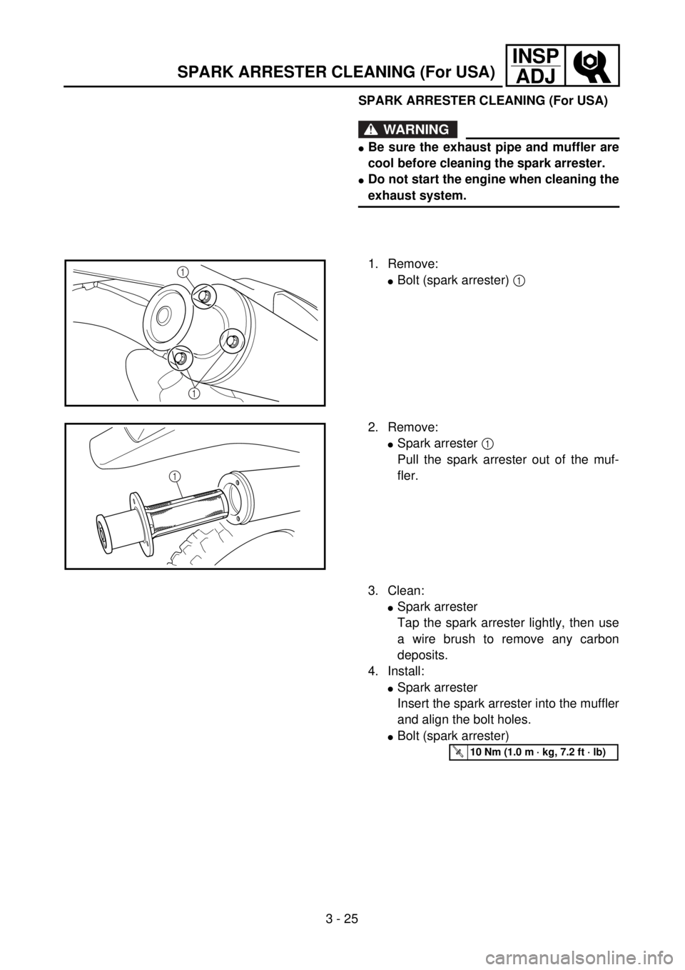
SPARK ARRESTER CLEANING (For USA)
WARNING
lBe sure the exhaust pipe and muffler are
cool before cleaning the spark arrester.
lDo not start the engine when cleaning the
exhaust system.
1. Remove:
lBolt (spark arrester) 1 1
1
2. Remove:
lSpark arrester 1
Pull the spark arrester out of the muf-
fler.
1
3. Clean:
lSpark arrester
Tap the spark arrester lightly, then use
a wire brush to remove any carbon
deposits.
4. Install:
lSpark arrester
Insert the spark arrester into the muffler
and align the bolt holes.
lBolt (spark arrester)
T R..10 Nm (1.0 m · kg, 7.2 ft · lb)
SPARK ARRESTER CLEANING (For USA)
Page 217 of 686
INSP
ADJ
NETTOYAGE DU PARE-ETINCELLES (pour les USA)/
FUNKENFÄNGER REINIGEN (NUR USA)
PULIZIA DEL PARASCINTILLE (Per USA)
FUNKENFÄNGER REINIGEN (NUR
USA)
WARNUNG
lKrümmer und Schalldämpfer
vor Beginn dieser Arbeit abküh-
len lassen.
lDen Motor während dieser
Arbeit nicht anlassen.
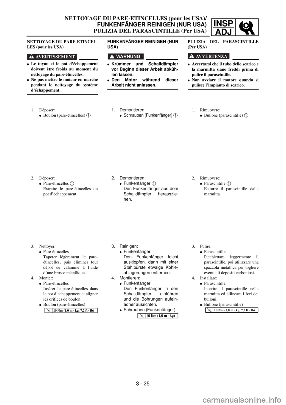
1. Demontieren:
lSchrauben (Funkenfänger) 1
2. Demontieren:
lFunkenfänger 1
Den Funkenfänger aus dem
Schalldämpfer herauszie-
hen.
3. Reinigen:
lFunkenfänger
Den Funkenfänger leicht
ausklopfen, dann mit einer
Stahlbürste etwaige Kohle-
ablagerungen entfernen.
4. Montieren:
lFunkenfänger
Den Funkenfänger in den
Schalldämpfer einführen
und die Bohrungen aufein-
adner ausrichten.
lSchrauben (Funkenfänger)
T R..10 Nm (1,0 m · kg)
NETTOYAGE DU PARE-ETINCEL-
LES (pour les USA)
AVERTISSEMENT
lLe tuyau et le pot d’échappement
doivent être froids au moment du
nettoyage du pare-étincelles.
lNe pas mettre le moteur en marche
pendant le nettoyage du système
d’échappement.
1. Déposer:
lBoulon (pare-étincelles) 1
2. Déposer:
lPare-étincelles 1
Extraire le pare-étincelles du
pot d’échappement.
3. Nettoyer:
lPare-étincelles
Tapoter légèrement le pare-
étincelles, puis éliminer tout
dépôt de calamine à l’aide
d’une brosse métallique.
4. Monter:
lPare-étincelles
Insérer le pare-étincelles dans
le pot d’échappement et aligner
les orifices de boulon.
lBoulon (pare-étincelles)
T R..10 Nm (1,0 m · kg, 7,2 ft · lb)
PULIZIA DEL PARASCINTILLE
(Per USA)
AVVERTENZA
lAccertarsi che il tubo dello scarico e
la marmitta siano freddi prima di
pulire il parascintille.
lNon avviare il motore quando si
pulisce l’impianto di scarico.
1. Rimuovere:
lBullone (parascintille) 1
2. Rimuovere:
lParascintille 1
Estrarre il parascintille dalla
marmitta.
3. Pulire:
lParascintille
Picchiettare leggermente il
parascintille, poi utilizzare una
spazzola metallica per togliere
eventuali depositi carboniosi.
4. Installare:
lParascintille
Inserire il parascintille nella
marmitta ed allineare i fori dei
bulloni.
lBullone (parascintille)
T R..10 Nm (1,0 m · kg, 7,2 ft · lb)
3 - 25
Page 218 of 686

3 - 26
INSP
ADJ
CHASSIS/BRAKE SYSTEM AIR BLEEDING
EC360000
CHASSIS
EC361012
BRAKE SYSTEM AIR BLEEDING
WARNING
Bleed the brake system if:
lThe system has been disassembled.
lA brake hose has been loosened or
removed.
lThe brake fluid is very low.
lThe brake operation is faulty.
A dangerous loss of braking performance
may occur if the brake system is not prop-
erly bleed.
1. Remove:
lReservoir cap
lDiaphragm
lProtector (rear brake)
2. Bleed:
lBrake fluid
Front
õRear
Air bleeding steps:
a. Add proper brake fluid to the reservoir.
b. Install the diaphragm. Be careful not to
spill any fluid or allow the reservoir to
overflow.
c. Connect the clear plastic tube 2 tightly
to the caliper bleed screw 1.
d. Place the other end of the tube into a
container.
e. Slowly apply the brake lever or pedal
several times.
f. Pull the lever in or push down on the
pedal. Hold the lever or pedal in position.
g. Loosen the bleed screw and allow the
lever or pedal to travel towards its limit.
h. Tighten the bleed screw when the lever
or pedal limit has been reached; then
release the lever or pedal.
T R..
Bleed screw:
6 Nm (0.6 m • kg, 4.3 ft • lb)
i. Repeat steps (e) to (h) until of the air
bubbles have been removed from the
system.
õ
Page 219 of 686
INSP
ADJPARTIE CYCLE/PURGE DE L’AIR DU SYSTEME DE FREINAGE
FAHRWERK/HYDRAULISCHE BREMSANLAGE ENTLÜFTEN
PARTE CICLISTICA/SPURGO DELL’ARIA DAL SISTEMA FRENANTE
FAHRWERK
HYDRAULISCHE BREMSANLAGE
ENTLÜFTEN
WARNUNG
Die Anlage muß entlüftet werden,
wenn:
ldie Anlage zerlegt wurde,
lein Schlauch gelöst oder erneu-
ert wurde,
lder Flüssigkeitsstand sehr nied-
rig ist,
ldie Anlage nicht einwandfrei
funktioniert.
Eine nicht korrekt durchgeführte
Entlüftung kann zur Verminderung
der Bremsleistung führen.
1. Demontieren:
lBehälterdeckel
lMembran
lProtektor (Hinterradbremse)
2. Entlüften:
lBremsflüssigkeit
Vorn
õHinten
Arbeitsschritte
a. Ausgleichsbehälter mit der
empfohlenen Bremsflüssigkeit
befüllen. Darauf achten, daß
keine Flüssigkeit verschüttet
wird und der Ausgleichsbehäl-
ter nicht überläuft.
b. Membran einsetzen.
c. Durchsichtigen Kunststoff-
schlauch 2 fest auf Entlüf-
tungsschraube 1 aufstecken.
d. Freies Schlauchende in Auf-
fangbehälter führen.
e. Hand- bzw. Fußbremshebel
mehrmals langsam betätigen.
f. Handbremshebel ziehen bzw.
Fußbremshebel drücken und
in dieser Stellung halten.
g. Entlüftungsschraube lockern
und Hand- bzw. Fußbrems-
hebel bis zum Anschlag
bewegen.
h. Entlüftungsschraube festzie-
hen, danach Hand- bzw. Fuß-
bremshebel loslassen.
T R..
Entlüftungsschraube
6 Nm (0,6 m • kg)
i. Schritte (e) bis (h) solange
wiederholen, bis sich keine
Luftblasen mehr im Kunst-
stoffschlauch befinden.
PARTIE CYCLE
PURGE DE L’AIR DU SYSTEME
DE FREINAGE
AVERTISSEMENT
Purger le système de freinage si:
lLe système a été démonté.
lUn tuyau de frein a été desserré ou
deposé.
lLe liquide de frein est très bas.
lLe frein fonctionne mal.
Si le système de freinage n’est pas cor-
rectement purgé, cela peut se traduire
par une dangereuse perte d’efficacité
de freinage.
1. Déposer:
lBouchon du réservoir
lDiaphragme
lProtection (frein arrière)
2. Purger:
lLiquide de frein
Avant
õArrière
Etapes de purge de l’air:
a. Ajouter du liquide de frein cor-
rect dans le réservoir.
b. Mettre en place le diaphragme.
Prendre garde à ne pas renverser
ou faire déborder le réservoir.
c. Connecter hermétiquement le
tuyau transparent en matière
plastique 2, à la vis de purge 1
de l’étrier.
d. Mettre l’autre extrémité du
tuyau dans un récipient.
e. Actionner légèrement plusieurs
fois le levier ou la pédale de
frein.
f. Appuyer sur le levier ou la
pédale de frein et le maintenir
dans cette position.
g. Desserrer la vis de purge et lais-
ser le levier ou la pédale
s’enfoncer sur toute sa course.
h. Resserrer la vis de purge quand
le levier ou la pédale a atteint sa
limite.
Relâcher ensuite le levier ou la
pédale.
T R..
Vis de purge:
6 Nm
(0,6 m • kg, 4,3 ft • lb)
i. Refaire le opérations (e) à (h)
jusqu’à l’élimination totale des
bulles d’air du système.
PARTE CICLISTICA
SPURGO DELL’ARIA DAL
SISTEMA FRENANTE
AVVERTENZA
Spurgare il sistema frenante se:
lIl sistema è stato smontato.
lUn tubo flessibile è stato allentato o
rimosso.
lIl livello del liquido dei freni è molto
basso.
lL’azionamento del freno è difettoso.
Se il sistema non viene spurgato cor-
rettamente, potrebbe verificarsi un
pericoloso calo nelle prestazioni di fre-
natura.
1. Rimuovere:
lTappo del serbatoio
lDiaframma
lDispositivo di protezione
(freno posteriore)
2. Spurgare:
lLiquido dei freni
Anteriore
õPosteriore
Fasi per lo spurgo dell’aria:
a. Aggiungere il liquido per freni
idoneo nel serbatoio.
b. Installare il diaframma. Atten-
zione a non versare il liquido o a
non far traboccare il liquido dal
serbatoio.
c. Collegare fermamente il tubo di
plastica trasparente 2 alla val-
volina di spurgo 1 della pinza.
d. Posizionare l’altra estremità del
tubo in un contenitore.
e. Agire ripetutamente lentamente
sulla leva o sul pedale del freno.
f. Tirare la leva o premere il
pedale. Mantenere la leva o il
pedale in posizione.
g. Svitare la valvolina di spurgo e
raggiungere il limite di corsa
della leva o del pedale.
h. Avvitare la valvolina di spurgo
quando si raggiunge il limite di
corsa della leva o del pedale,
quindi rilasciare la leva o il
pedale.
T R..
Valvolina di spurgo:
6 Nm
(0,6 m • kg. 4,3 ft • lb)
i. Ripetere i punti da (e) a (h) fino
a rimuovere tutte le bolle d’aria
dal sistema.
3 - 26
Page 220 of 686
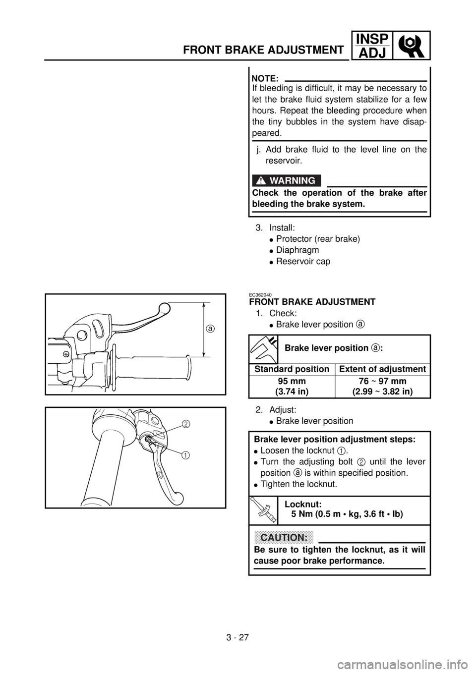
3 - 27
INSP
ADJ
FRONT BRAKE ADJUSTMENT
3. Install:
lProtector (rear brake)
lDiaphragm
lReservoir cap
NOTE:
If bleeding is difficult, it may be necessary to
let the brake fluid system stabilize for a few
hours. Repeat the bleeding procedure when
the tiny bubbles in the system have disap-
peared.
j. Add brake fluid to the level line on the
reservoir.
WARNING
Check the operation of the brake after
bleeding the brake system.
EC362040
FRONT BRAKE ADJUSTMENT
1. Check:
lBrake lever position a
Brake lever position a:
Standard position Extent of adjustment
95 mm
(3.74 in)76 ~ 97 mm
(2.99 ~ 3.82 in)
2. Adjust:
lBrake lever position
Brake lever position adjustment steps:
lLoosen the locknut 1.
lTurn the adjusting bolt 2 until the lever
position a is within specified position.
lTighten the locknut.
T R..
Locknut:
5 Nm (0.5 m • kg, 3.6 ft • lb)
CAUTION:
Be sure to tighten the locknut, as it will
cause poor brake performance.
2
1