oil change YAMAHA WR 250F 2001 Owners Manual
[x] Cancel search | Manufacturer: YAMAHA, Model Year: 2001, Model line: WR 250F, Model: YAMAHA WR 250F 2001Pages: 686, PDF Size: 62.6 MB
Page 8 of 686

6. GASOLINE CAN CAUSE INJURY.
If you should swallow some gasoline,
inhale excess gasoline vapors, or
allow any gasoline to get into your
eyes, contact a doctor immediately. If
any gasoline spills onto your skin or
clothing, immediately wash skin areas
with soap and water, and change your
clothes.
7. ONLY OPERATE THE MACHINE IN AN
AREA WITH ADEQUATE VENTILA-
TION.
Never start the engine or let it run for
any length of time in an enclosed area.
Exhaust fumes are poisonous. These
fumes contain carbon monoxide,
which by itself is odorless and color-
less. Carbon monoxide is a dangerous
gas which can cause unconscious-
ness or can be lethal.
8. PARK THE MACHINE CAREFULLY;
TURN OFF THE ENGINE.
Always turn off the engine if you are
going to leave the machine. Do not
park the machine on a slope or soft
ground as it may fall over.
9. THE ENGINE EXHAUST PIPE, MUF-
FLER, AND OIL TANK WILL BE VERY
HOT AFTER THE ENGINE HAS BEEN
RUN.
Be careful not to touch them or to
allow any clothing item to contact
them during inspection or repair.
10. PROPERLY SECURE THE MACHINE
BEFORE TRANSPORTING IT.
When transporting the machine in
another vehicle, always be sure it is
properly secured and in an upright
position and that the fuel cock is in
the “OFF” position. Otherwise, fuel
may leak out of the carburetor or fuel
tank.
Page 26 of 686
GEN
INFO
1 - 1
DESCRIPTION
EC100000
GENERAL INFORMATION
EC110000
DESCRIPTION
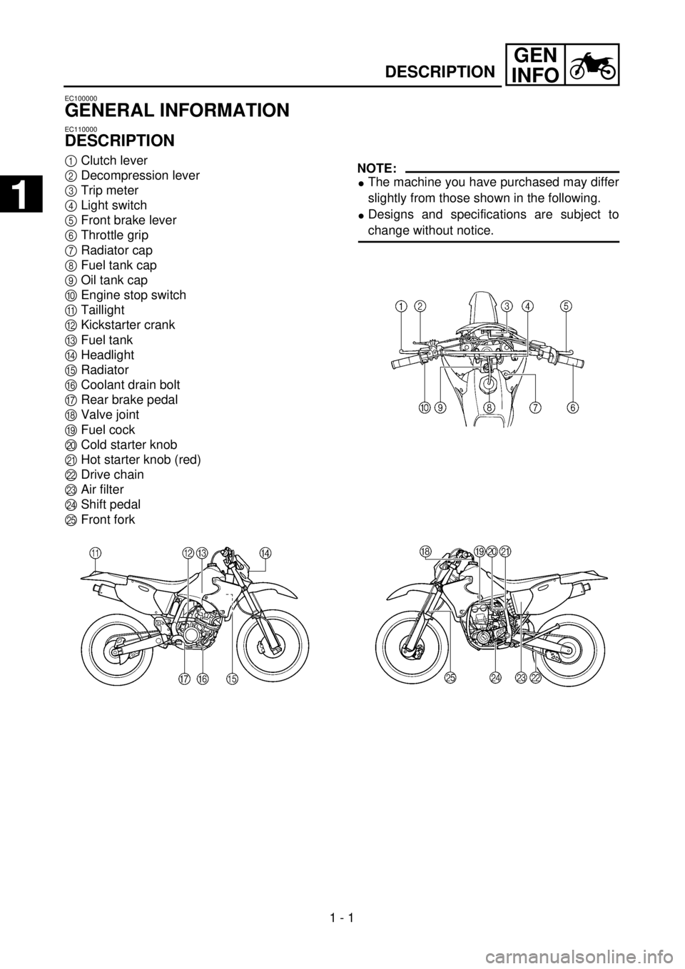
1
Clutch lever
2
Decompression lever
3
Trip meter
4
Light switch
5
Front brake lever
6
Throttle grip
7
Radiator cap
8
Fuel tank cap
9
Oil tank cap
0
Engine stop switch
A
Taillight
B
Kickstarter crank
C
Fuel tank
D
Headlight
E
Radiator
F
Coolant drain bolt
G
Rear brake pedal
H
Valve joint
I
Fuel cock
J
Cold starter knob
K
Hot starter knob (red)
L
Drive chain
M
Air filter
N
Shift pedal
O
Front fork
NOTE:
l
The machine you have purchased may differ
slightly from those shown in the following.
l
Designs and specifications are subject to
change without notice.
1
Page 75 of 686
SPEC
2 - 2
GENERAL SPECIFICATIONS
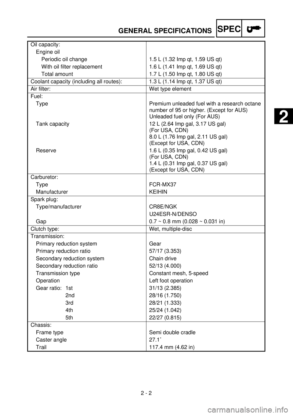
Oil capacity:
Engine oil
Periodic oil change 1.5 L (1.32 Imp qt, 1.59 US qt)
With oil filter replacement 1.6 L (1.41 Imp qt, 1.69 US qt)
Total amount 1.7 L (1.50 Imp qt, 1.80 US qt)
Coolant capacity (including all routes): 1.3 L (1.14 Imp qt, 1.37 US qt)
Air filter: Wet type element
Fuel:
Type Premium unleaded fuel with a research octane
number of 95 or higher. (Except for AUS)
Unleaded fuel only (For AUS)
Tank capacity 12 L (2.64 Imp gal, 3.17 US gal)
(For USA, CDN)
8.0 L (1.76 Imp gal, 2.11 US gal)
(Except for USA, CDN)
Reserve 1.6 L (0.35 Imp gal, 0.42 US gal)
(For USA, CDN)
1.4 L (0.31 Imp gal, 0.37 US gal)
(Except for USA, CDN)
Carburetor:
Type FCR-MX37
Manufacturer KEIHIN
Spark plug:
Type/manufacturer CR8E/NGK
U24ESR-N/DENSO
Gap 0.7 ~ 0.8 mm (0.028 ~ 0.031 in)
Clutch type: Wet, multiple-disc
Transmission:
Primary reduction system Gear
Primary reduction ratio 57/17 (3.353)
Secondary reduction system Chain drive
Secondary reduction ratio 52/13 (4.000)
Transmission type Constant mesh, 5-speed
Operation Left foot operation
Gear ratio: 1st 31/13 (2.385)
2nd 28/16 (1.750)
3rd 28/21 (1.333)
4th 25/24 (1.042)
5th 22/27 (0.815)
Chassis:
Frame type Semi double cradle
Caster angle 27.1˚
Trail 117.4 mm (4.62 in)
2
Page 158 of 686
3 - 1
INSP
ADJ
MAINTENANCE INTERVALS
EC300000
REGULAR INSPECTION AND ADJUSTMENTS
MAINTENANCE INTERVALS
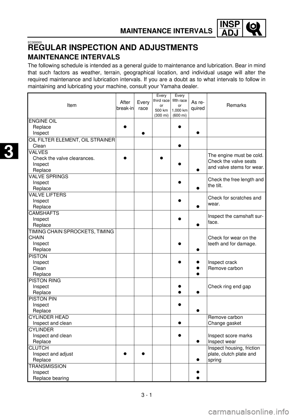
The following schedule is intended as a general guide to maintenance and lubrication. Bear in mind
that such factors as weather, terrain, geographical location, and individual usage will alter the
required maintenance and lubrication intervals. If you are a doubt as to what intervals to follow in
maintaining and lubricating your machine, consult your Yamaha dealer.
ItemAfter
break-inEvery
race
Every
third race
or
500 km
(300 mi)Every
fifth race
or
1,000 km
(600 mi)
As re-
quiredRemarks
ENGINE OIL
Replace
Inspect
c
cc
c
OIL FILTER ELEMENT, OIL STRAINER
Clean
c
VALVES
Check the valve clearances.
Inspect
Replace
c
c
c
c
The engine must be cold.
Check the valve seats
and valve stems for wear.
VALVE SPRINGS
Inspect
Replace
c
c
Check the free length and
the tilt.
VALVE LIFTERS
Inspect
Replace
c
c
Check for scratches and
wear.
CAMSHAFTS
Inspect
Replace
c
c
Inspect the camshaft sur-
face.
TIMING CHAIN SPROCKETS, TIMING
CHAIN
Inspect
Replace
c
c
Check for wear on the
teeth and for damage.
PISTON
Inspect
Clean
Replace
c
c
c
c
Inspect crack
Remove carbon
PISTON RING
Inspect
Replace
c
c
c
Check ring end gap
PISTON PIN
Inspect
Replace
c
c
CYLINDER HEAD
Inspect and clean
c
Remove carbon
Change gasket
CYLINDER
Inspect and clean
Replace
c
c
Inspect score marks
Inspect wear
CLUTCH
Inspect and adjust
Replace
c
c
c
Inspect housing, friction
plate, clutch plate and
spring
TRANSMISSION
Inspect
Replace bearing
c
c
3
Page 198 of 686

3 - 17
INSP
ADJ
ENGINE OIL REPLACEMENT
7. If the oil filter is to be replaced during this
oil change, remove the following parts
and reinstall them.
8. Install:
lCopper washer 1
lOil strainer (frame) 2
lOil hose 3
lBolt (oil hose) 4
lOil hose clamp 5
lLower engine bracket
9. Install:
lCopper washer
lOil filter element drain bolt
lCrankcase oil drain bolt
lFrame oil drain bolt
10. Fill:
lEngine oil
11. Check:
lOil leakage
12. Install:
lOil tank cap
13. Check:
lEngine oil level Replacement steps:
lRemove the oil filter element cover 1 and
oil filter element 2.
lCheck the O-rings 3, if cracked or dam-
aged, replace them with a new one.
lInstall the oil filter element and oil filter ele-
ment cover.
T R..
Oil filter element cover:
10 Nm (1.0 m • kg, 7.2 ft • lb)
Oil quantity:
Total amount:
1.7 L (1.50 Imp qt, 1.80 US qt)
Periodic oil change:
1.5 L (1.32 Imp qt, 1.59 US qt)
With oil filter replacement:
1.6 L (1.41 Imp qt, 1.69 US qt)
T R..90 Nm (9.0 m · kg, 65 ft · lb)
T R..10 Nm (1.0 m · kg, 7.2 ft · lb)
T R..2 Nm (0.2 m · kg, 1.4 ft · lb)
T R..10 Nm (1.0 m · kg, 7.2 ft · lb)
T R..10 Nm (1.0 m · kg, 7.2 ft · lb)
T R..20 Nm (2.0 m · kg, 14 ft · lb)
T R..23 Nm (2.3 m · kg, 17 ft · lb)
Page 371 of 686
ENG
4 - 52
EMBRAYAGE
KUPPLUNG
FRIZIONE
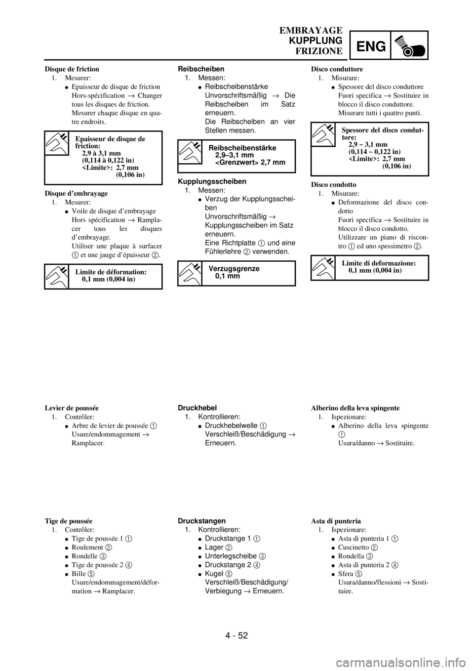
Reibscheiben
1. Messen:
lReibscheibenstärke
Unvorschriftsmäßig ® Die
Reibscheiben im Satz
erneuern.
Die Reibscheiben an vier
Stellen messen.
Kupplungsscheiben
1. Messen:
lVerzug der Kupplungsschei-
ben
Unvorschriftsmäßig ®
Kupplungsscheiben im Satz
erneuern.
Eine Richtplatte 1 und eine
Fühlerlehre 2 verwenden.
Reibscheibenstärke
2,9–3,1 mm
Verzugsgrenze
0,1 mm
Druckhebel
1. Kontrollieren:
lDruckhebelwelle 1
Verschleiß/Beschädigung ®
Erneuern.
Druckstangen
1. Kontrollieren:
lDruckstange 1 1
lLager 2
lUnterlegscheibe 3
lDruckstange 2 4
lKugel 5
Verschleiß/Beschädigung/
Verbiegung ® Erneuern. Disque de friction
1. Mesurer:
lEpaisseur de disque de friction
Hors-spécification ® Changer
tous les disques de friction.
Mesurer chaque disque en qua-
tre endroits.
Disque d’embrayage
1. Mesurer:
lVoile de disque d’embrayage
Hors spécification ® Rampla-
cer tous les disques
d’embrayage.
Utiliser une plaque à surfacer
1 et une jauge d’épaisseur 2.
Epaisseur de disque de
friction:
2,9 à 3,1 mm
(0,114 à 0,122 in)
(0,106 in)
Limite de déformation:
0,1 mm (0,004 in)
Levier de poussée
1. Contrôler:
lArbre de levier de poussée 1
Usure/endommagement ®
Ramplacer.
Tige de poussée
1. Contrôler:
lTige de poussée 1 1
lRoulement 2
lRondelle 3
lTige de poussée 2 4
lBille 5
Usure/endommagement/défor-
mation ® Ramplacer.Disco conduttore
1. Misurare:
lSpessore del disco conduttore
Fuori specifica ® Sostituire in
blocco il disco conduttore.
Misurare tutti i quattro punti.
Disco condotto
1. Misurare:
lDeformazione del disco con-
dotto
Fuori specifica ® Sostituire in
blocco il disco condotto.
Utilizzare un piano di riscon-
tro 1 ed uno spessimetro 2.
Spessore del disco condut-
tore:
2,9 ~ 3,1 mm
(0,114 ~ 0,122 in)
(0,106 in)
Limite di deformazione:
0,1 mm (0,004 in)
Alberino della leva spingente
1. Ispezionare:
lAlberino della leva spingente
1
Usura/danno ® Sostituire.
Asta di punteria
1. Ispezionare:
lAsta di punteria 1 1
lCuscinetto 2
lRondella 3
lAsta di punteria 2 4
lSfera 5
Usura/danno/flessioni ® Sosti-
tuire.
Page 382 of 686
4 - 58
ENG
OIL FILTER ELEMENT, WATER PUMP AND RIGHT
CRANKCASE COVER
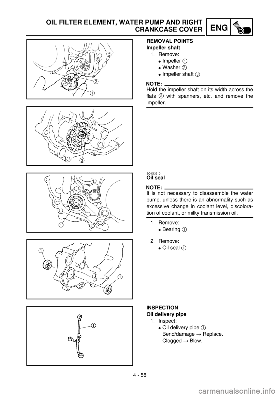
REMOVAL POINTS
Impeller shaft
1. Remove:
lImpeller 1
lWasher 2
lImpeller shaft 3
NOTE:
Hold the impeller shaft on its width across the
flats a with spanners, etc. and remove the
impeller.
EC4G3210
Oil seal
NOTE:
It is not necessary to disassemble the water
pump, unless there is an abnormality such as
excessive change in coolant level, discolora-
tion of coolant, or milky transmission oil.
1. Remove:
lBearing 1
2. Remove:
lOil seal 1
INSPECTION
Oil delivery pipe
1. Inspect:
lOil delivery pipe 1
Bend/damage ® Replace.
Clogged ® Blow.
Page 473 of 686
5 - 3
CHAS
ROUE AVANT ET ROUE ARRIERE
VORDER- UND HINTERRAD
RUOTA ANTERIORE E RUOTA POSTERIORE
AUSBAU
Hinterrad
1. Demontieren:
l
Rad
1
HINWEIS:
Das Rad nach vorne stoßen und die
Antriebskette
2
abnehmen.
Radlager (nach Bedarf)
1. Demontieren:
l
Lager
1
HINWEIS:
Die Lager mit einem Lageraustreiber
2
ausbauen.
PRÜFUNG
Rad
1. Messen:
l
Felgenschlag
Unvorschriftsmäßig
®
Instand setzen/Erneuern.
Max. Felgenschlag
Höhenschlag
1
2,0 mm
Seitenschlag
2
2,0 mm
2. Kontrollieren:
l
Lager
Den inneren Laufring mit
dem Finger drehen.
Schwergängigkeit/Freßspu-
ren
®
Erneuern.
HINWEIS:
Lager, Dichtringe und Hülse im Satz
erneuern.
POINTS DE DEPOSE
Roue arrière
1. Déposer:
l
Roue
1
N.B.:
Pousser la roue vers l’avant et déposer la
chaîne de transmission
2
.
Roulement de roue (si nécessaire)
1. Déposer:
l
Roulement
1
N.B.:
Déposer le roulement en utilisant un
arrache-roulement courant 2.
CONTROLE
Roue
1. Mesure:
lVoile de roue
Hors limite ® Réparer/rempla-
cer.
Limite de voile de la roue:
Radial 1: 2,0 mm
(0,08 in)
Latéral 2: 2,0 mm
(0,08 in)
2. Contrôler:
lRoulement
Faire tourner la bague inté-
rieure avec le doigt.
Point dur/grippage ® Rempla-
cer.
N.B.:
Changer à la fois les roulements, la
bague d’étanchéité et la collerette de
roue.PUNTI DI RIMOZIONE
Ruota posteriore
1. Rimuovere:
lRuota 1
NOTA:
Spingere la ruota in avanti e rimuovere
la catena di trasmissione 2.
Cuscinetto della ruota (se necessario)
1. Rimuovere:
lCuscinetto 1
NOTA:
Rimuovere il cuscinetto impiegando un
estrattore per cuscinetti 2.
ISPEZIONE
Ruota
1. Misurare:
lScentratura
Fuori limite ® Riparare/sosti-
tuire.
Limite di disassamento
ruota:
Radiale 1: 2,0 mm
(0,08 in)
Laterale 2: 2,0 mm
(0,08 in)
2. Ispezionare:
lCuscinetto
Far ruotare l’anello interno con
un dito.
Punti rugosi/grippaggio ®
Sostituire.
NOTA:
Sostituire in blocco i cuscinetti, il parao-
lio ed il collarino della ruota.
Page 475 of 686
5 - 4
CHAS
ROUE AVANT ET ROUE ARRIERE
VORDER- UND HINTERRAD
RUOTA ANTERIORE E RUOTA POSTERIORE
Radachse
1. Messen:
lRadachsschlag
Unvorschriftsmäßig ®
Erneuern.
Die Meßuhr 1 verwenden.
HINWEIS:
Der Radachsschlag entspricht der
Hälfte der Meßuhranzeige.
WARNUNG
Nie versuchen, eine verbogene
Achse zu richten.
Max. Radachsschlag
0,5 mm
Bremsscheibe
1. Messen:
lBremsscheibenschlag (nur
Hinterrad-Bremsscheibe)
Die Meßuhr 1 verwenden.
Unvorschriftsmäßig ® Fel-
genschlag prüfen.
Falls im Sollbereich, die
Bremsscheibe erneuern.
2. Messen:
lBremsscheibenstärke a
Unvorschriftsmäßig ®
Erneuern.
Max. Bremsscheiben-
verzug
Hinten
Bremsscheiben-Min-
deststärke
Vorn
3,0 mm
Hinten
4,0 mm
Axe de roue
1. Mesurer:
lDéformation de l’axe de roue
Hors-spécification ® Rempla-
cer.
Utiliser le comparateur 1.
N.B.:
La valeur de déformation est égale à la
moitié de la lecture du comparateur.
AVERTISSEMENT
Ne jamais tenter de redresser un axe
tordu.
Limite de déformation de
l’axe de roue:
0,5 mm (0,020 in)
Disque de frein
1. Mesurer:
lDéflexion de disque de frein
(disque de frein arrière unique-
ment)
Utiliser le comparateur 1.
Hors spécification ® Exami-
ner le voile de roue.
Si le voile de la roue est nor-
mal, changer le disque de frein.
2. Mesurer:
lEpaisseur de disque de frein a
Hors limite ® Remplacer.
Limite de déflexion de dis-
que:
Arrière:
(0,006 in)
Limite d’usure de disque:
Avant:
3,0 mm (0,12 in)
(0,10 in)
Arrière:
4,0 mm (0,16 in)
(0,14 in)
Asse della ruota
1. Misurare:
lDeformazioni asse della ruota
Fuori specifica ® Regolare.
Utilizzare un comparatore 1.
NOTA:
Il valore di deformazione corrisponde
alla metà del valore indicato dal compa-
ratore.
AVVERTENZA
Non tentare di raddrizzare un asse
deformato.
Limite di deformazione
dell’asse della ruota:
0,5 mm (0,020 in)
Disco freno
1. Misurare:
lDeflessione disco del freno
(solo disco del freno poste-
riore)
Utilizzare un comparatore 1.
Fuori specifica ® Ispezionare
il disassamento della ruota.
Se il disassamento è in buone
condizioni, sostituire il disco
del freno.
2. Misurare:
lSpessore del disco del freno a
Fuori limite ® Sostituire.
Limite di deflessione del
disco freno:
Posteriore:
(0,006 in)
Spessore del disco freno:
Anteriore:
3,0 mm (0,12 in)
(0,10 in)
Posteriore:
4,0 mm (0,16 in)
(0,14 in)
Page 660 of 686
7 - 13
TUNSETTING
EC722011
Front fork setting
The front fork setting should be made depend-
ing on the rider’s feeling of an actual run and
the circuit conditions.
The front fork setting includes the following
three factors:
1. Setting of air spring characteristics
lChange the fork oil level.
2. Setting of spring preload
lChange the spring.
lInstall the adjustment washer.
3. Setting of damping force
lChange the compression damping.
lChange the rebound damping.
The spring acts on the load and the
damping force acts on the cushion
travel speed.
EC723001
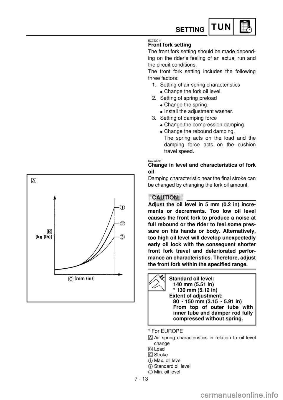
Change in level and characteristics of fork
oil
Damping characteristic near the final stroke can
be changed by changing the fork oil amount.
CAUTION:
Adjust the oil level in 5 mm (0.2 in) incre-
ments or decrements. Too low oil level
causes the front fork to produce a noise at
full rebound or the rider to feel some pres-
sure on his hands or body. Alternatively,
too high oil level will develop unexpectedly
early oil lock with the consequent shorter
front fork travel and deteriorated perfor-
mance an characteristics. Therefore, adjust
the front fork within the specified range.
* For EUROPE
Air spring characteristics in relation to oil level
change
õLoad
‚Stroke
1Max. oil level
2Standard oil level
3Min. oil level
Standard oil level:
140 mm (5.51 in)
* 130 mm (5.12 in)
Extent of adjustment:
80 ~ 150 mm (3.15 ~ 5.91 in)
From top of outer tube with
inner tube and damper rod fully
compressed without spring.