light YAMAHA WR 250F 2003 Notices Demploi (in French)
[x] Cancel search | Manufacturer: YAMAHA, Model Year: 2003, Model line: WR 250F, Model: YAMAHA WR 250F 2003Pages: 860, PDF Size: 35.16 MB
Page 93 of 860

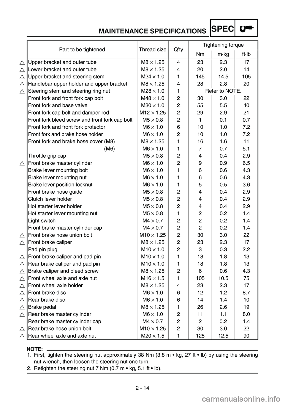
MAINTENANCE SPECIFICATIONS
2 - 14
SPEC
NOTE:
1. First, tighten the steering nut approximately 38 Nm (3.8 m kg, 27 ft lb) by using the steering
nut wrench, then loosen the steering nut one turn.
2. Retighten the steering nut 7 Nm (0.7 m kg, 5.1 ft lb). Part to be tightened Thread size Q’tyTightening torque
Nm m·kg ft·lb
Upper bracket and outer tube M8 × 1.25 4 23 2.3 17
Lower bracket and outer tube M8 × 1.25 4 20 2.0 14
Upper bracket and steering stem M24 × 1.0 1 145 14.5 105
Handlebar upper holder and upper bracket M8 × 1.25 4 28 2.8 20
Steering stem and steering ring nut M28 × 1.0 1 Refer to NOTE.
Front fork and front fork cap bolt M48 × 1.0 2 30 3.0 22
Front fork and base valve M30 × 1.0 2 55 5.5 40
Front fork cap bolt and damper rod M12 × 1.25 2 29 2.9 21
Front fork bleed screw and front fork cap bolt M5 × 0.8 2 1 0.1 0.7
Front fork and front fork protector M6 × 1.0 6 10 1.0 7.2
Front fork and brake hose holder M6 × 1.0 2 10 1.0 7.2
Front fork and brake hose cover (M8) M8 × 1.25 1 16 1.6 11
(M6) M6 × 1.0 1 7 0.7 5.1
Throttle grip cap M5 × 0.8 2 4 0.4 2.9
Front brake master cylinder M6 × 1.0 2 9 0.9 6.5
Brake lever mounting bolt M6 × 1.0 1 6 0.6 4.3
Brake lever mounting nut M6 × 1.0 1 6 0.6 4.3
Brake lever position locknut M6 × 1.0 1 5 0.5 3.6
Front brake hose guide M5 × 0.8 2 4 0.4 2.9
Clutch lever holder M5 × 0.8 2 4 0.4 2.9
Hot starter lever holder M5 × 0.8 2 4 0.4 2.9
Hot starter lever mounting nut M5 × 0.8 1 2 0.2 1.4
Light switch M4 × 0.7 2 2 0.2 1.4
Front brake master cylinder cap M4 × 0.7 2 2 0.2 1.4
Front brake hose union bolt M10 × 1.25 2 30 3.0 22
Front brake caliper M8 × 1.25 2 23 2.3 17
Pad pin plug M10 × 1.0 2 3 0.3 2.2
Front brake caliper and pad pin M10 × 1.0 1 18 1.8 13
Rear brake caliper and pad pin M10 × 1.0 1 18 1.8 13
Brake caliper and bleed screw M8 × 1.25 2 6 0.6 4.3
Front wheel axle and axle nut M16 × 1.5 1 105 10.5 75
Front wheel axle holder M8 × 1.25 4 23 2.3 17
Front brake disc M6 × 1.0 6 12 1.2 8.7
Rear brake disc M6 × 1.0 6 14 1.4 10
Brake pedal M8 × 1.25 1 26 2.6 19
Rear brake master cylinder M6 × 1.0 2 11 1.1 8.0
Rear brake master cylinder cap M4 × 0.7 2 2 0.2 1.4
Rear brake hose union bolt M10 × 1.25 2 30 3.0 22
Rear wheel axle and axle nut M20 × 1.5 1 125 12.5 90
Page 94 of 860

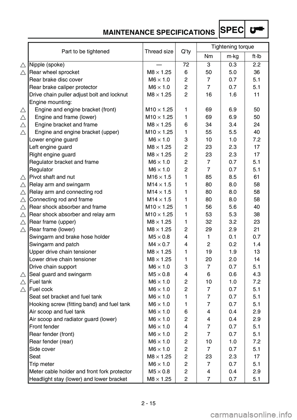
MAINTENANCE SPECIFICATIONS
2 - 15
SPEC
Part to be tightened Thread size Q’tyTightening torque
Nm m·kg ft·lb
Nipple (spoke)—72 3 0.3 2.2
Rear wheel sprocket M8 × 1.25 6 50 5.0 36
Rear brake disc cover M6 × 1.0 2 7 0.7 5.1
Rear brake caliper protector M6 × 1.0 2 7 0.7 5.1
Drive chain puller adjust bolt and locknut M8 × 1.25 2 16 1.6 11
Engine mounting:
Engine and engine bracket (front) M10 × 1.25 1 69 6.9 50
Engine and frame (lower) M10 × 1.25 1 69 6.9 50
Engine bracket and frame M8 × 1.25 6 34 3.4 24
Engine and engine bracket (upper) M10 × 1.25 1 55 5.5 40
Lower engine guard M6 × 1.0 3 10 1.0 7.2
Left engine guard M8 × 1.25 2 23 2.3 17
Right engine guard M8 × 1.25 2 23 2.3 17
Regulator bracket and frame M6 × 1.0 2 7 0.7 5.1
Regulator M6 × 1.0 2 7 0.7 5.1
Pivot shaft and nut M16 × 1.5 1 85 8.5 61
Relay arm and swingarm M14 × 1.5 1 80 8.0 58
Relay arm and connecting rod M14 × 1.5 1 80 8.0 58
Connecting rod and frame M14 × 1.5 1 80 8.0 58
Rear shock absorber and frame M10 × 1.25 1 56 5.6 40
Rear shock absorber and relay arm M10 × 1.25 1 53 5.3 38
Rear frame (upper) M8 × 1.25 1 32 3.2 23
Rear frame (lower) M8 × 1.25 2 29 2.9 21
Swingarm and brake hose holder M5 × 0.8 4 1 0.1 0.7
Swingarm and patch M4 × 0.7 4 2 0.2 1.4
Upper drive chain tensioner M8 × 1.25 1 19 1.9 13
Lower drive chain tensioner M8 × 1.25 1 20 2.0 14
Drive chain support M6 × 1.0 3 7 0.7 5.1
Seal guard and swingarm M5 × 0.8 4 6 0.6 4.3
Fuel tank M6 × 1.0 2 10 1.0 7.2
Fuel cock M6 × 1.0 2 7 0.7 5.1
Seat set bracket and fuel tank M6 × 1.0 1 7 0.7 5.1
Hooking screw (fitting band) and fuel tank M6 × 1.0 1 7 0.7 5.1
Air scoop and fuel tank M6 × 1.0 6 4 0.4 2.9
Air scoop and radiator guard (lower) M6 × 1.0 2 4 0.4 2.9
Front fender M6 × 1.0 4 7 0.7 5.1
Rear fender (front) M6 × 1.0 2 7 0.7 5.1
Rear fender (rear) M6 × 1.0 2 10 1.0 7.2
Side cover M6 × 1.0 2 7 0.7 5.1
Seat M8 × 1.25 2 23 2.3 17
Trip meter M6 × 1.0 2 7 0.7 5.1
Meter cable holder and front fork protector M5 × 0.8 2 4 0.4 2.9
Headlight stay (lower) and lower bracket M8 × 1.25 2 7 0.7 5.1
Page 95 of 860

MAINTENANCE SPECIFICATIONS
2 - 16
SPEC
NOTE:
- marked portion shall be checked for torque tightening after break-in or before each race. Headlight body and headlight unit M6 × 1.0 2 7 0.7 5.1
Headlight (left and right) M6 × 1.0 2 10 1.0 7.2
Headlight (lower) M6 × 1.0 1 7 0.7 5.1
Taillight M6 × 1.0 3 4 0.4 2.9
Taillight lead clamp and rear fender M4 × 1.59 2 0.5 0.05 0.36
Coolant reservoir M6 × 1.0 2 7 0.7 5.1
Sidestand bracket and frame M10 × 1.25 2 66 6.6 48
Sidestand M10 × 1.25 1 64 6.4 46 Part to be tightened Thread size Q’tyTightening torque
Nm m·kg ft·lb
Page 96 of 860

MAINTENANCE SPECIFICATIONS
2 - 17
SPEC
EC212300
ELECTRICAL
Item Standard Limit
Ignition system:
Advancer type Electrical ----
CDI:
Pickup coil resistance (color) 248 ~ 372 Ω at 20°C (68 °F)
(White – Red)----
CDI unit-model/manufacturer 5UM-00/YAMAHA (For USA) ----
5UM-10/YAMAHA (Except for USA) ----
Ignition coil:
Model/manufacturer 5UL-00/DENSO ----
Minimum spark gap 6 mm (0.24 in) ----
Primary coil resistance 0.08 ~ 0.10 Ω at 20 °C (68 °F) ----
Secondary coil resistance 4.6 ~ 6.8 kΩ at 20 °C (68 °F) ----
Charging system:
System type AC magneto ----
Model/manufacturer 5UM-00/YAMAHA ----
Normal output 14 V/120 W at 5,000 r/min ----
Charging coil resistance (color) 0.288 ~ 0.432 Ω at 20 °C (68 °F)
(White – Ground)----
Lighting coil resistance (color) 0.224 ~ 0.336 Ω at 20 °C (68 °F)
(Yellow – Ground)----
Rectifier/regulator:
Regulator type Semiconductor short circuit ----
Model/manufacture SH712AA/SHINDENGEN ----
Regulated voltage (AC) 13.0 ~ 14.0 V ----
Regulated voltage (DC) 14.1 ~ 14.9 V ----
Rectifier capacity (AC) 12 A ----
Rectifier capacity (DC) 8 A ----
Electric starting system:
Type Constant mesh ----
Starter motor:
Model/manufacturer 5UM00/YAMAHA ----
Operation voltage 12 V ----
Output 0.35 kW ----
Armature coil resistance 0.0189 ~ 0.0231 Ω at 20 °C (68 °F) ----
Brush overall length 7 mm (0.28 in) 3.5 mm (0.14 in)
Brush quantity 2 pcs. ----
Spring force 3.92 ~ 5.88 N
(400 ~ 600 g, 14.1 ~ 21.2 oz)----
Commutator diameter 17.6 mm (0.69 in) 16.6 mm (0.65 in)
Mica undercut (depth) 1.5 mm (0.06 in) ----
Page 176 of 860

SPEC
2 - 97
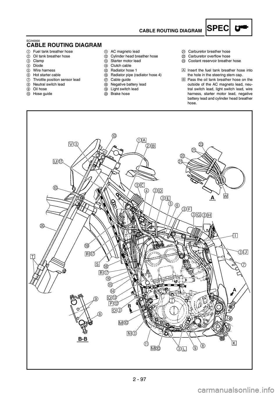
CABLE ROUTING DIAGRAM
EC240000
CABLE ROUTING DIAGRAM
1Fuel tank breather hose
2Oil tank breather hose
3Clamp
4Diode
5Wire harness
6Hot starter cable
7Throttle position sensor lead
8Neutral switch lead
9Oil hose
0Hose guideAAC magneto lead
BCylinder head breather hose
CStarter motor lead
DClutch cable
ERadiator hose 1
FRadiator pipe (radiator hose 4)
GCable guide
HNegative battery lead
ILight switch lead
JBrake hoseKCarburetor breather hose
LCarburetor overflow hose
MCoolant reservoir breather hose
ÈInsert the fuel tank breather hose into
the hole in the steering stem cap.
ÉPass the oil tank breather hose on the
outside of the AC magneto lead, neu-
tral switch lead, light switch lead, wire
harness, starter motor lead, negative
battery lead and cylinder head breather
hose.
Page 180 of 860

SPEC
2 - 101
CABLE ROUTING DIAGRAM
ÖFasten the neutral switch lead and AC magneto lead.
×Pass the cylinder head breather hose on the inside of the radi-
ator hose 1 and on the outside of the radiator pipe (radiator
hose 4). Make sure that the cylinder head breather hose does
not go forward of the chassis.
ØPass the starter motor lead in front of the radiator hose 4.
ÙPass the clutch cable through the cable guide.
ÚPass the wire harness on the outside of the neutral switch lead
and AC magneto lead.
ÛFit the brake hose into the guides on the protector.
ÜPass the wire harness, clutch cable and light switch lead
through the cable guide.ÝFasten the AC magneto lead, neutral switch lead and light
switch lead to the cable guide at their protecting tube with a
plastic locking tie and cut off the tie end.
ÞPass the carburetor breather hoses, carburetor overflow hose
and coolant reservoir breather hose so that the hoses do not
contact the rear shock absorber.
Page 186 of 860

SPEC
2 - 107
CABLE ROUTING DIAGRAM
1Brake master cylinder
2Brake hose holder
3Brake hoseÈInstall the brake hose so that its pipe portion directs as shown
and lightly touches the projection on the brake caliper.
ÉPass the brake hose into the brake hose holders.
ÊIf the brake hose contacts the spring (rear shock absorber),
correct its twist.
ËInstall the brake hose so that its pipe portion directs as shown
and lightly touches the projection on the brake master cylinder.
Page 188 of 860

SPEC
2 - 109
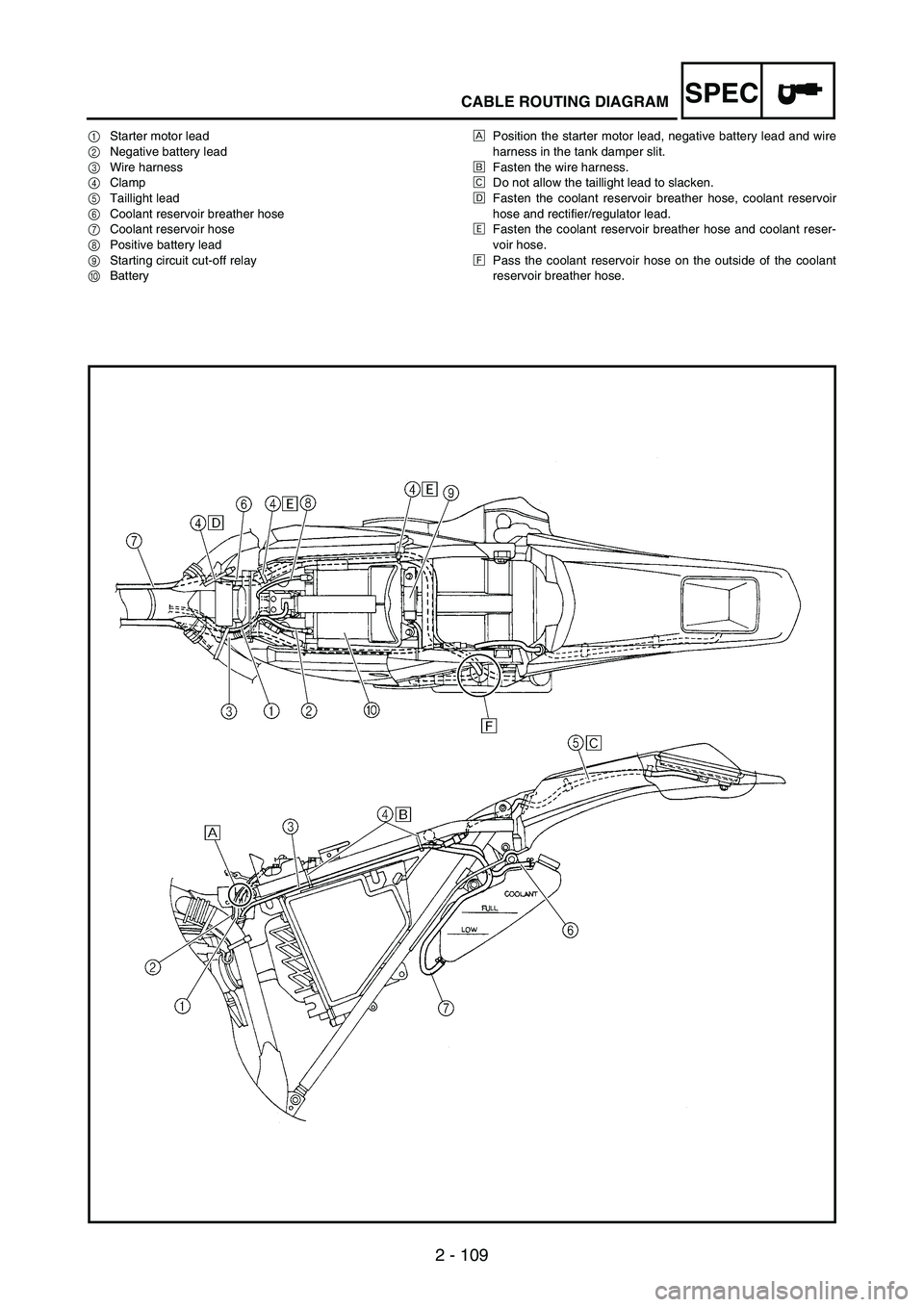
CABLE ROUTING DIAGRAM
1Starter motor lead
2Negative battery lead
3Wire harness
4Clamp
5Taillight lead
6Coolant reservoir breather hose
7Coolant reservoir hose
8Positive battery lead
9Starting circuit cut-off relay
0BatteryÈPosition the starter motor lead, negative battery lead and wire
harness in the tank damper slit.
ÉFasten the wire harness.
ÊDo not allow the taillight lead to slacken.
ËFasten the coolant reservoir breather hose, coolant reservoir
hose and rectifier/regulator lead.
ÌFasten the coolant reservoir breather hose and coolant reser-
voir hose.
ÍPass the coolant reservoir hose on the outside of the coolant
reservoir breather hose.
Page 190 of 860

SPEC
2 - 111
CABLE ROUTING DIAGRAM
1Throttle cable
2Brake hose
3Clamp
4Light switch lead
5Hot starter cable
6Clutch cable
7Hose guide
8Clutch switch lead
9Engine stop switch lead
0Trip meter cable
AMain switch lead
BTrip meter
CMain switchDLight switch
EStart switch lead
ÈFasten the start switch lead and light switch lead.
ÉFasten the engine stop switch lead and clutch switch lead.
ÊPass the brake hose through the hose guide.
ËPass the start switch lead in front of the main switch lead.
ÌFasten the start switch lead.
ÍPass the hot starter cable, clutch cable and light switch lead
between the upper bracket and coupler bracket.
ÎPass the throttle cables between the upper bracket and trip
meter.
Page 230 of 860

3 - 39
INSP
ADJ
ENGINE OIL LEVEL INSPECTION
1. Start the engine, warm it up for
several minutes, and then turn
off the engine and wait for five
minutes.
2. Place the machine on a level
place and hold it up on upright
position by placing the suitable
stand under the engine.
3. Remove:
Oil tank cap
1
1
4. Inspect:
Oil level
Oil level should be between
maximum
a and minimum b
marks.
Oil level is low → Add oil to
proper level.
NOTE:When inspecting the oil level, do not
screw the oil tank cap into the oil
tank. Insert the gauge lightly.
(For USA and CDN)
CAUTION:
Do not add any chemical addi-
tives. Engine oil also lubricates
the clutch and additives could
cause clutch slippage.
Do not allow foreign material to
enter the crankcase.
Recommended oil:
At 5 °C (40 °F) or
higher È Yamalube 4
(20W-40) or SAE 20W-
40 type SG motor oil
(Non-Friction
modified)
At 15 °C (60 °F) or
lower É Yamalube 4
(10W-30) or SAE 10W-
30 type SG motor oil
(Non-Friction modified)
and/or
Yamalube 4-R (15W-50)
(Non-Friction modified)
a
b
CONTROLE DU NIVEAU D’HUILE
MOTEUR
1. Mettre le moteur en marche, le faire
chauffer pendant quelques minutes,
puis le couper et attendre cinq
minutes.
2. Placer le véhicule sur un plan hori-
zontal et le dresser à la verticale en
plaçant un support adéquat sous le
moteur.
3. Déposer:
Bouchon du réservoir d’huile 1
4. Contrôler:
Niveau d’huile
Le niveau d’huile doit se trouver
entre les repères maximum a et
minimum b.
Bas niveau d’huile → Ajouter de
l’huile jusqu’au niveau requis.
N.B.:
Pour mesurer le niveau d’huile, intro-
duire la jauge dans le réservoir en
veillant à ne pas la visser.
(USA et CDN)
ATTENTION:
Ne pas ajouter d’additifs chimiques.
L’huile moteur lubrifie également
l’embrayage et des additifs risquent
de provoquer le patinage de
l’embrayage.
Empêcher toute pénétration de
crasses ou d’objets dans le carter.
Huile recommandée:
Min. 5 °C (40 °F) È:
Yamalube 4 (20W40) ou
SAE 20W-40 de type SG
(Sans additifs anti-
friction)
Max. 15 °C (60 °F) É:
Yamalube 4 (10W-30) ou
SAE 10W-30 de type SG
(Sans additifs anti-
friction)
et/ou
Yamalube 4-R (15W-50)
(Sans additifs anti-
friction)
ENGINE
MOTEUR