check engine YAMAHA WR 250F 2003 Owner's Guide
[x] Cancel search | Manufacturer: YAMAHA, Model Year: 2003, Model line: WR 250F, Model: YAMAHA WR 250F 2003Pages: 860, PDF Size: 35.16 MB
Page 786 of 860

6 - 53
–+ELECTHROTTLE POSITION SENSOR SYSTEM
THROTTLE POSITION SENSOR SYSTEM
INSPECTION STEPS
If the throttle position sensor will not operate, use the following inspection steps.
NOTE:Use the following special tools in this inspection.
Check entire ignition
system for connection.Repair or replace.
Check throttle position sensor.Throttle position
sensor coilReplace.
Check CDI unit.Throttle position
sensor input
voltageReplace.
Pocket tester:
YU-3112-C/
90890-03112
Inductive tachometer:
YU-8036-B
Engine tachometer:
90890-03113
No good
OK
No good
OK
No good
Page 792 of 860

6 - 59
–+ELECTHROTTLE POSITION SENSOR SYSTEM
HANDLING NOTE
CAUTION:
Do not loosen the screws (throttle
position sensor) 1
except when
changing the throttle position sen-
sor due to failure because it will
cause a drop in engine perfor-
mance.
1
EC624000COUPLERS AND LEADS
CONNECTION INSPECTION
1. Check:
Couplers and leads connec-
tion
Rust/dust/looseness/short-cir-
cuit
→ Repair or replace.
THROTTLE POSITION SENSOR
COIL INSPECTION
1. Inspect:
Throttle position sensor coil
resistance
Out of specification
→
Replace.
Tester (+) lead →
Blue lead 1
Tester (–) lead →
Black lead 2
Throttle
position
sensor coil
resistanceTester
selector
position
4 ~ 6 kΩ at
20 °C (68 °F)kΩ × 1
2. Loosen:
Throttle stop screw 1
NOTE:Turn out the throttle stop screw until
the throttle shaft is in the full close
position.
REMARQUE
ATTENTION:
Ne pas desserrer les vis (capteur de
position des gaz) 1 sauf s’il faut chan-
ger le capteur de position en raison
d’un problème, sinon le moteur sera
moins performant.
CONTROLE DES CONNEXIONS
DES COUPLEURS ET DES FILS
1. Contrôler:
Connexion coupleurs et fils
Rouille/poussière/desserrement/
court-circuit → Réparer ou rem-
placer.
CONTROLE DE LA BOBINE DE
CAPTEUR DE PAPILLON DES
GAZ
1. Contrôler:
Résistance de la bobine du cap-
teur de papillon des gaz
Hors spécifications → Rempla-
cer.
Fil (+) de multimètre → Fil bleu 1
Fil (–) de multimètre → Fil noir 2
Résistance de la
bobine du
capteur de
papillon des gaz Position de
sélecteur du
multimètre
4 à 6 kΩ à
20 °C (68 °F)kΩ × 1
2. Desserrer:
Vis d’arrêt d’accélérateur 1
N.B.:
Tourner la vis d’arrêt d’accélérateur
jusqu’à ce que l’axe de l’accélérateur
soit en position de fermeture complète.
CIRCUIT DU CAPTEUR DE PAPILLON DES GAZ
Page 800 of 860

6 - 67
–+ELECLIGHTING SYSTEM
LIGHTING SYSTEM
INSPECTION STEPS
Refer to the following flow chart when inspecting the ignition system for possible problems.
NOTE:Replace the bulb and/or bulb socket.
1) Seat
2) Fuel tank
Use the following special tool.
Check the bulb and bulb socket.Replace the bulb and/or
bulb socket.
Check the light switch. Replace.
Check the AC magneto. Lighting coil Replace.
Check the entire lighting system
proper for connections.Repair or replace.
Check the rectifier/regulator. Out-put voltage Replace.
Pocket tester:
YU-3112-C/
90890-03112
Inductive tachometer:
YU-8036-B
Engine tachometer:
90890-03113
No good
OK
No good
OK
No good
OK
Improperly connected
OK
No good
Page 808 of 860

7 - 1
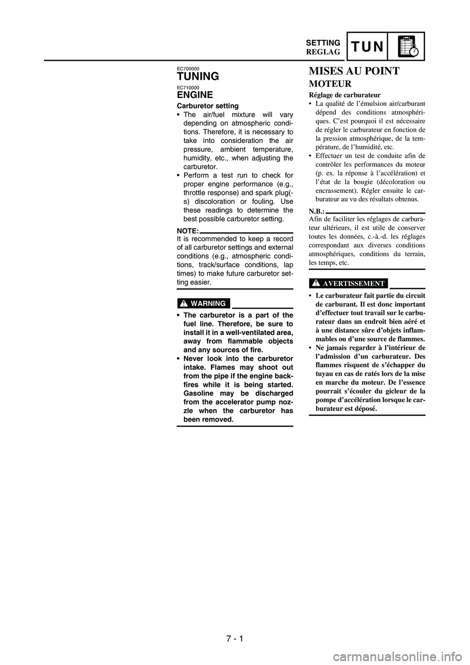
TUNSETTING
EC700000
TUNING
EC710000
ENGINE
Carburetor setting
The air/fuel mixture will vary
depending on atmospheric condi-
tions. Therefore, it is necessary to
take into consideration the air
pressure, ambient temperature,
humidity, etc., when adjusting the
carburetor.
Perform a test run to check for
proper engine performance (e.g.,
throttle response) and spark plug(-
s) discoloration or fouling. Use
these readings to determine the
best possible carburetor setting.
NOTE:It is recommended to keep a record
of all carburetor settings and external
conditions (e.g., atmospheric condi-
tions, track/surface conditions, lap
times) to make future carburetor set-
ting easier.
WARNING
The carburetor is a part of the
fuel line. Therefore, be sure to
install it in a well-ventilated area,
away from flammable objects
and any sources of fire.
Never look into the carburetor
intake. Flames may shoot out
from the pipe if the engine back-
fires while it is being started.
Gasoline may be discharged
from the accelerator pump noz-
zle when the carburetor has
been removed.
MISES AU POINT
MOTEUR
Réglage de carburateur
La qualité de l’émulsion air/carburant
dépend des conditions atmosphéri-
ques. C’est pourquoi il est nécessaire
de régler le carburateur en fonction de
la pression atmosphérique, de la tem-
pérature, de l’humidité, etc.
Effectuer un test de conduite afin de
contrôler les performances du moteur
(p. ex. la réponse à l’accélération) et
l’état de la bougie (décoloration ou
encrassement). Régler ensuite le car-
burateur au vu des résultats obtenus.
N.B.:
Afin de faciliter les réglages de carbura-
teur ultérieurs, il est utile de conserver
toutes les données, c.-à.-d. les réglages
correspondant aux diverses conditions
atmosphériques, conditions du terrain,
les temps, etc.
AVERTISSEMENT
Le carburateur fait partie du circuit
de carburant. Il est donc important
d’effectuer tout travail sur le carbu-
rateur dans un endroit bien aéré et
à une distance sûre d’objets inflam-
mables ou d’une source de flammes.
Ne jamais regarder à l’intérieur de
l’admission d’un carburateur. Des
flammes risquent de s’échapper du
tuyau en cas de ratés lors de la mise
en marche du moteur. De l’essence
pourrait s’écouler du gicleur de la
pompe d’accélération lorsque le car-
burateur est déposé.
REGLAG
Page 810 of 860

7 - 3
TUNSETTING
CAUTION:
The carburetor is extremely sen-
sitive to foreign matter (dirt,
sand, water, etc.). During instal-
lation, do not allow foreign mat-
ter to get into the carburetor.
Always handle the carburetor
and its components carefully.
Even slight scratches, bends or
damage to carburetor parts may
prevent the carburetor from
functioning correctly. Carefully
perform all servicing with the
appropriate tools and without
applying excessive force.
When the engine is stopped or
when riding at no load, do not
open and close the throttle
unnecessarily. Otherwise, too
much fuel may be discharged,
starting may become difficult or
the engine may not run well.
After installing the carburetor,
check that the throttle operates
correctly and opens and closes
smoothly.
Atmospheric conditions and
carburetor settings
The air density (i.e., concentration
of oxygen in the air) determines
the richness or leanness of the air/
fuel mixture. Therefore, refer to the
above table for mixture settings.
That is:
Higher temperature expands the
air with its resultant reduced den-
sity.
Higher humidity reduces the
amount of oxygen in the air by so
much of the water vapor in the
same air.
Lower atmospheric pressure (at a
high altitude) reduces the density
of the air.
Air temp. HumidityAir
pressure
(altitude)Mixture Setting
High High Low (high) Richer Leaner
Low Low High (low) Leaner Richer
ATTENTION:
Le carburateur est extrêmement
sensible à toute pénétration de cras-
ses, sable, eau, etc. Bien veiller, lors
de tout travail sur le carburateur,
d’empêcher toute pénétration
d’objets quelconques.
Toujours manipuler le carburateur
et ses organes avec le plus grand
soin. Même de légères griffes, défor-
mations ou petits endommagements
peuvent empêcher son bon fonction-
nement. Effectuer soigneusement
tous les entretiens avec les outils
appropriés et sans recourir à une
force excessive.
Ne pas actionner sans raison la poi-
gnée des gaz lorsque le moteur est
coupé ou lorsqu’il tourne à vide. En
effet, cela provoquerait un apport
excédentaire en essence, rendant
difficile la mise en marche du
moteur ou entraînant son mauvais
fonctionnement.
Après la remise en place du carbu-
rateur, s’assurer que la poignée des
gaz fonctionne correctement.
Conditions atmosphériques et réglages
de carburateur
La densité de l’air, c.-à-d. la concen-
tration d’oxygène dans l’air, déter-
mine la richesse ou la pauvreté de
l’émulsion air/carburant. Il convient
dès lors de se conformer au tableau ci-
dessus.
La densité de l’air varie en fonction des
trois facteurs suivants:
La température de l’air: la densité de
l’air diminue au fur et à mesure que
l’air se dilate sous les températures
élevées.
Le taux d’humidité de l’air: le taux
d’oxygène diminue au fur et à mesure
que le taux d’humidité augmente.
Pression atmosphérique (altitude): la
densité diminue au fur et à mesure que
la pression atmosphérique descend
(altitude élevée).
Tempé-
ratureHumiditéPression
atmos-
phérique
(altitude)Emulsion Réglage
Haute HauteBasse
(haute)Plus
richePlus
pauvre
Basse BasseHaute
(basse)Plus
pauvrePlus
riche
REGLAG
Page 824 of 860

7 - 17
TUNSETTING
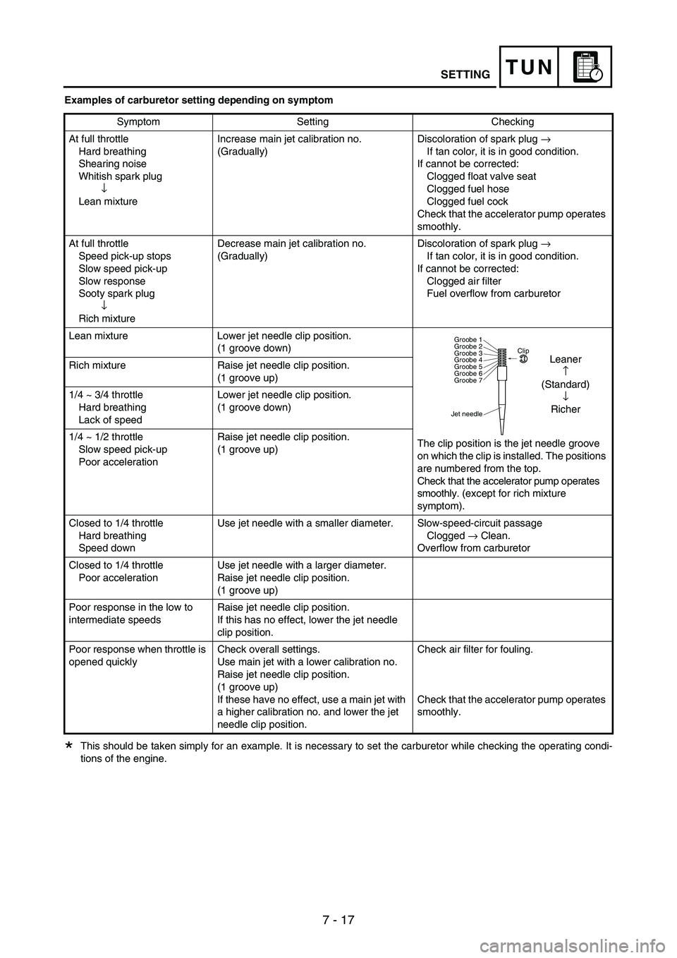
Examples of carburetor setting depending on symptom
This should be taken simply for an example. It is necessary to set the carburetor while checking the operating condi-
tions of the engine.Symptom Setting Checking
At full throttle
Hard breathing
Shearing noise
Whitish spark plug
↓
Lean mixtureIncrease main jet calibration no.
(Gradually)Discoloration of spark plug
→
If tan color, it is in good condition.
If cannot be corrected:
Clogged float valve seat
Clogged fuel hose
Clogged fuel cock
Check that the accelerator pump operates
smoothly.
At full throttle
Speed pick-up stops
Slow speed pick-up
Slow response
Sooty spark plug
↓
Rich mixtureDecrease main jet calibration no.
(Gradually)Discoloration of spark plug
→
If tan color, it is in good condition.
If cannot be corrected:
Clogged air filter
Fuel overflow from carburetor
Lean mixture Lower jet needle clip position.
(1 groove down)
The clip position is the jet needle groove
on which the clip is installed. The positions
are numbered from the top.
Check that the accelerator pump operates
smoothly. (except for rich mixture
symptom). Rich mixture Raise jet needle clip position.
(1 groove up)
1/4 ~ 3/4 throttle
Hard breathing
Lack of speedLower jet needle clip position.
(1 groove down)
1/4 ~ 1/2 throttle
Slow speed pick-up
Poor accelerationRaise jet needle clip position.
(1 groove up)
Closed to 1/4 throttle
Hard breathing
Speed downUse jet needle with a smaller diameter. Slow-speed-circuit passage
Clogged
→ Clean.
Overflow from carburetor
Closed to 1/4 throttle
Poor accelerationUse jet needle with a larger diameter.
Raise jet needle clip position.
(1 groove up)
Poor response in the low to
intermediate speedsRaise jet needle clip position.
If this has no effect, lower the jet needle
clip position.
Poor response when throttle is
opened quicklyCheck overall settings.
Use main jet with a lower calibration no.
Raise jet needle clip position.
(1 groove up)
If these have no effect, use a main jet with
a higher calibration no. and lower the jet
needle clip position.Check air filter for fouling.
Check that the accelerator pump operates
smoothly.
Jet needleClip
Groobe 7 Groobe 6
Groobe 5
Groobe 4
Groobe 3
Groobe 2
Groobe 1
Leaner
↑
(Standard)
↓
Richer
*