length YAMAHA WR 250F 2004 User Guide
[x] Cancel search | Manufacturer: YAMAHA, Model Year: 2004, Model line: WR 250F, Model: YAMAHA WR 250F 2004Pages: 864, PDF Size: 22.07 MB
Page 282 of 864
3 - 91
INSP
ADJ
EC36K000REAR SHOCK ABSORBER
INSPECTION
1. Inspect:
Swingarm smooth action
Abnormal noise/unsmooth
action
→ Grease the pivoting
points or repair the pivoting
points.
Damage/oil leakage
→
Replace.
REAR SHOCK ABSORBER
SPRING PRELOAD ADJUSTMENT
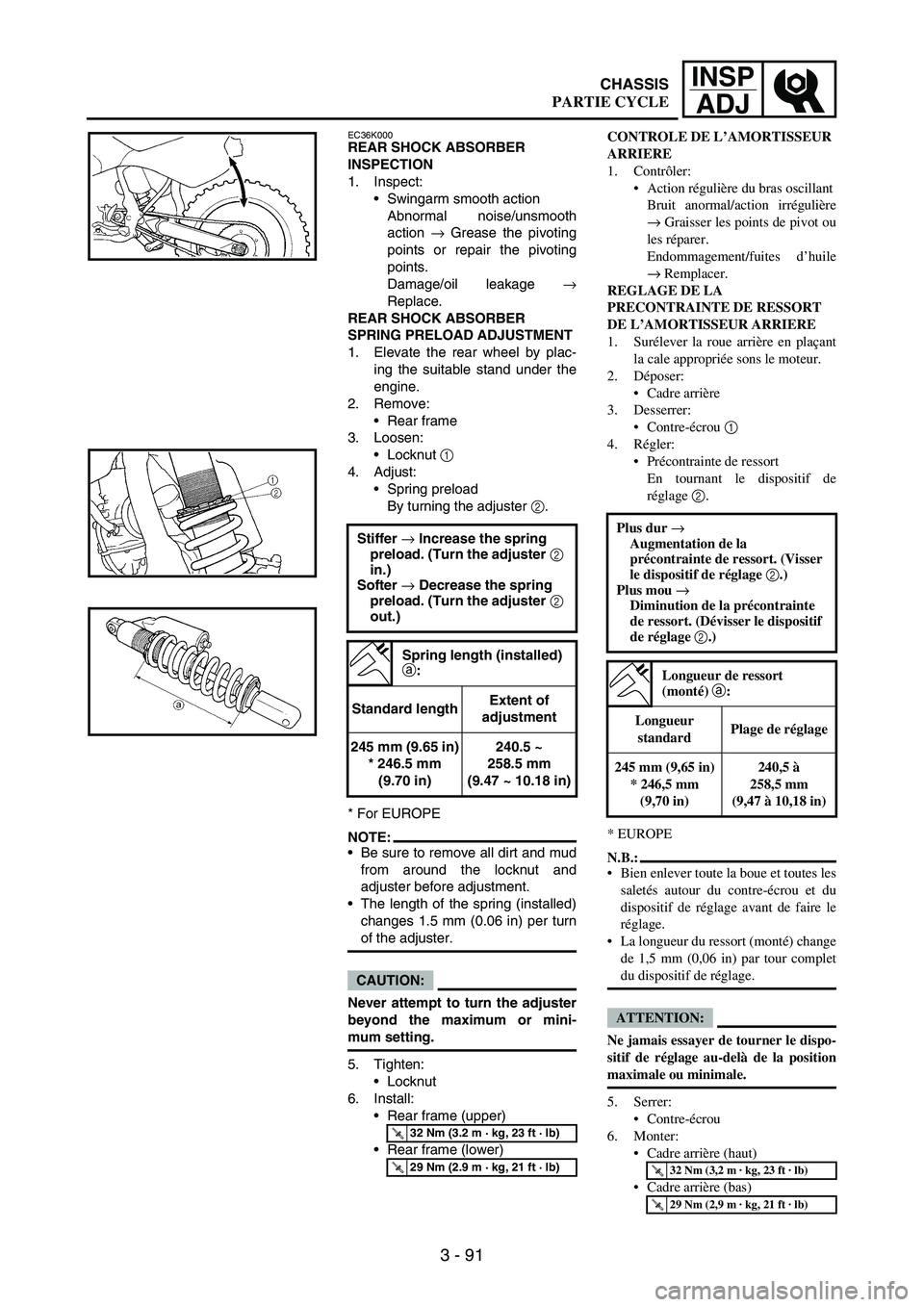
1. Elevate the rear wheel by plac-
ing the suitable stand under the
engine.
2. Remove:
Rear frame
3. Loosen:
Locknut
1
4. Adjust:
Spring preload
By turning the adjuster
2.
* For EUROPE
NOTE:Be sure to remove all dirt and mud
from around the locknut and
adjuster before adjustment.
The length of the spring (installed)
changes 1.5 mm (0.06 in) per turn
of the adjuster.
CAUTION:
Never attempt to turn the adjuster
beyond the maximum or mini-
mum setting.
5. Tighten:
Locknut
6. Install:
Rear frame (upper)
Rear frame (lower) Stiffer → Increase the spring
preload. (Turn the adjuster 2
in.)
Softer → Decrease the spring
preload. (Turn the adjuster 2
out.)
Spring length (installed)
a:
Standard lengthExtent of
adjustment
245 mm (9.65 in)
* 246.5 mm
(9.70 in)240.5 ~
258.5 mm
(9.47 ~ 10.18 in)
T R..32 Nm (3.2 m · kg, 23 ft · lb)
T R..29 Nm (2.9 m · kg, 21 ft · lb)
CONTROLE DE L’AMORTISSEUR
ARRIERE
1. Contrôler:
Action régulière du bras oscillant
Bruit anormal/action irrégulière
→ Graisser les points de pivot ou
les réparer.
Endommagement/fuites d’huile
→ Remplacer.
REGLAGE DE LA
PRECONTRAINTE DE RESSORT
DE L’AMORTISSEUR ARRIERE
1. Surélever la roue arrière en plaçant
la cale appropriée sons le moteur.
2. Déposer:
Cadre arrière
3. Desserrer:
Contre-écrou 1
4. Régler:
Précontrainte de ressort
En tournant le dispositif de
réglage 2.
* EUROPE
N.B.:
Bien enlever toute la boue et toutes les
saletés autour du contre-écrou et du
dispositif de réglage avant de faire le
réglage.
La longueur du ressort (monté) change
de 1,5 mm (0,06 in) par tour complet
du dispositif de réglage.
ATTENTION:
Ne jamais essayer de tourner le dispo-
sitif de réglage au-delà de la position
maximale ou minimale.
5. Serrer:
Contre-écrou
6. Monter:
Cadre arrière (haut)
Cadre arrière (bas) Plus dur →
Augmentation de la
précontrainte de ressort. (Visser
le dispositif de réglage 2.)
Plus mou →
Diminution de la précontrainte
de ressort. (Dévisser le dispositif
de réglage 2.)
Longueur de ressort
(monté) a:
Longueur
standardPlage de réglage
245 mm (9,65 in)
* 246,5 mm
(9,70 in)240,5 à
258,5 mm
(9,47 à 10,18 in)
T R..32 Nm (3,2 m · kg, 23 ft · lb)
T R..29 Nm (2,9 m · kg, 21 ft · lb)
CHASSIS
PARTIE CYCLE
Page 386 of 864
4 - 61
ENGCAMSHAFTS
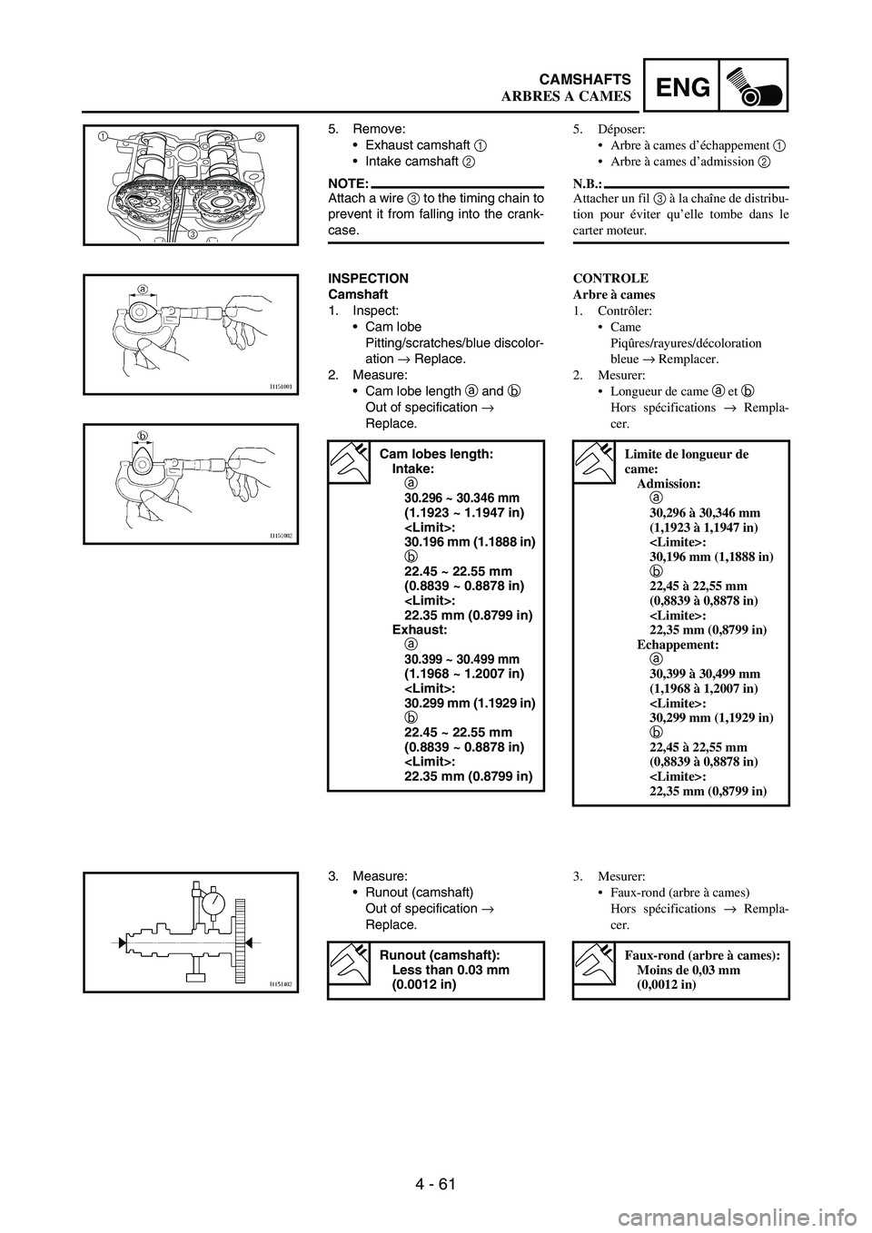
5. Remove:
Exhaust camshaft
1
Intake camshaft
2
NOTE:Attach a wire
3 to the timing chain to
prevent it from falling into the crank-
case.
1
2
3
INSPECTION
Camshaft
1. Inspect:
Cam lobe
Pitting/scratches/blue discolor-
ation
→ Replace.
2. Measure:
Cam lobe length
a and b
Out of specification →
Replace.
Cam lobes length:
Intake:
a
30.296 ~ 30.346 mm
(1.1923 ~ 1.1947 in)
30.196 mm (1.1888 in)
b
22.45 ~ 22.55 mm
(0.8839 ~ 0.8878 in)
22.35 mm (0.8799 in)
Exhaust:
a
30.399 ~ 30.499 mm
(1.1968 ~ 1.2007 in)
30.299 mm (1.1929 in)
b
22.45 ~ 22.55 mm
(0.8839 ~ 0.8878 in)
22.35 mm (0.8799 in)
3. Measure:
Runout (camshaft)
Out of specification →
Replace.
Runout (camshaft):
Less than 0.03 mm
(0.0012 in)
5. Déposer:
Arbre à cames d’échappement 1
Arbre à cames d’admission 2
N.B.:
Attacher un fil 3 à la chaîne de distribu-
tion pour éviter qu’elle tombe dans le
carter moteur.
CONTROLE
Arbre à cames
1. Contrôler:
Came
Piqûres/rayures/décoloration
bleue → Remplacer.
2. Mesurer:
Longueur de came a et b
Hors spécifications → Rempla-
cer.
Limite de longueur de
came:
Admission:
a
30,296 à 30,346 mm
(1,1923 à 1,1947 in)
30,196 mm (1,1888 in)
b
22,45 à 22,55 mm
(0,8839 à 0,8878 in)
22,35 mm (0,8799 in)
Echappement:
a
30,399 à 30,499 mm
(1,1968 à 1,2007 in)
30,299 mm (1,1929 in)
b
22,45 à 22,55 mm
(0,8839 à 0,8878 in)
22,35 mm (0,8799 in)
3. Mesurer:
Faux-rond (arbre à cames)
Hors spécifications → Rempla-
cer.
Faux-rond (arbre à cames):
Moins de 0,03 mm
(0,0012 in)
ARBRES A CAMES
Page 420 of 864
4 - 95
ENGVALVES AND VALVE SPRINGS
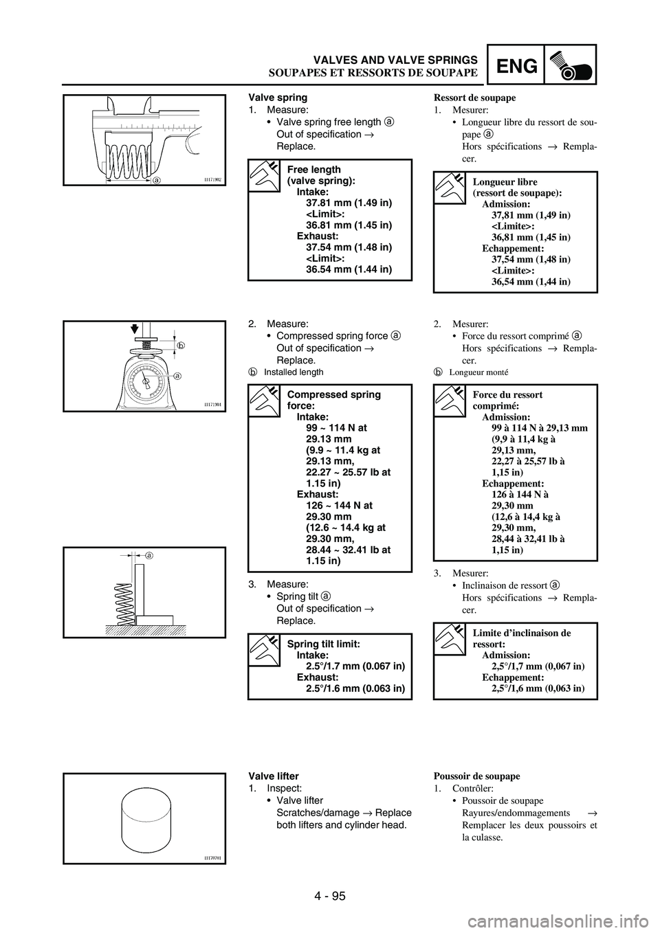
Valve spring
1. Measure:
Valve spring free length
a
Out of specification
→
Replace.
Free length
(valve spring):
Intake:
37.81 mm (1.49 in)
36.81 mm (1.45 in)
Exhaust:
37.54 mm (1.48 in)
36.54 mm (1.44 in)
2. Measure:
Compressed spring force
a
Out of specification
→
Replace.
b
Installed length
3. Measure:
Spring tilt
a
Out of specification
→
Replace.
Compressed spring
force:
Intake:
99 ~ 114 N at
29.13 mm
(9.9 ~ 11.4 kg at
29.13 mm,
22.27 ~ 25.57 lb at
1.15 in)
Exhaust:
126 ~ 144 N at
29.30 mm
(12.6 ~ 14.4 kg at
29.30 mm,
28.44 ~ 32.41 lb at
1.15 in)
Spring tilt limit:
Intake:
2.5°/1.7 mm (0.067 in)
Exhaust:
2.5°/1.6 mm (0.063 in)
Valve lifter
1. Inspect:
Valve lifter
Scratches/damage
→ Replace
both lifters and cylinder head.
Ressort de soupape
1. Mesurer:
Longueur libre du ressort de sou-
pape a
Hors spécifications → Rempla-
cer.
Longueur libre
(ressort de soupape):
Admission:
37,81 mm (1,49 in)
36,81 mm (1,45 in)
Echappement:
37,54 mm (1,48 in)
36,54 mm (1,44 in)
2. Mesurer:
Force du ressort comprimé a
Hors spécifications → Rempla-
cer.
b
Longueur monté
3. Mesurer:
Inclinaison de ressort a
Hors spécifications → Rempla-
cer.
Force du ressort
comprimé:
Admission:
99 à 114 N à 29,13 mm
(9,9 à 11,4 kg à
29,13 mm,
22,27 à 25,57 lb à
1,15 in)
Echappement:
126 à 144 N à
29,30 mm
(12,6 à 14,4 kg à
29,30 mm,
28,44 à 32,41 lb à
1,15 in)
Limite d’inclinaison de
ressort:
Admission:
2,5°/1,7 mm (0,067 in)
Echappement:
2,5°/1,6 mm (0,063 in)
Poussoir de soupape
1. Contrôler:
Poussoir de soupape
Rayures/endommagements →
Remplacer les deux poussoirs et
la culasse.
SOUPAPES ET RESSORTS DE SOUPAPE
Page 450 of 864
4 - 125
ENGCLUTCH
EC4A3000REMOVAL POINTS
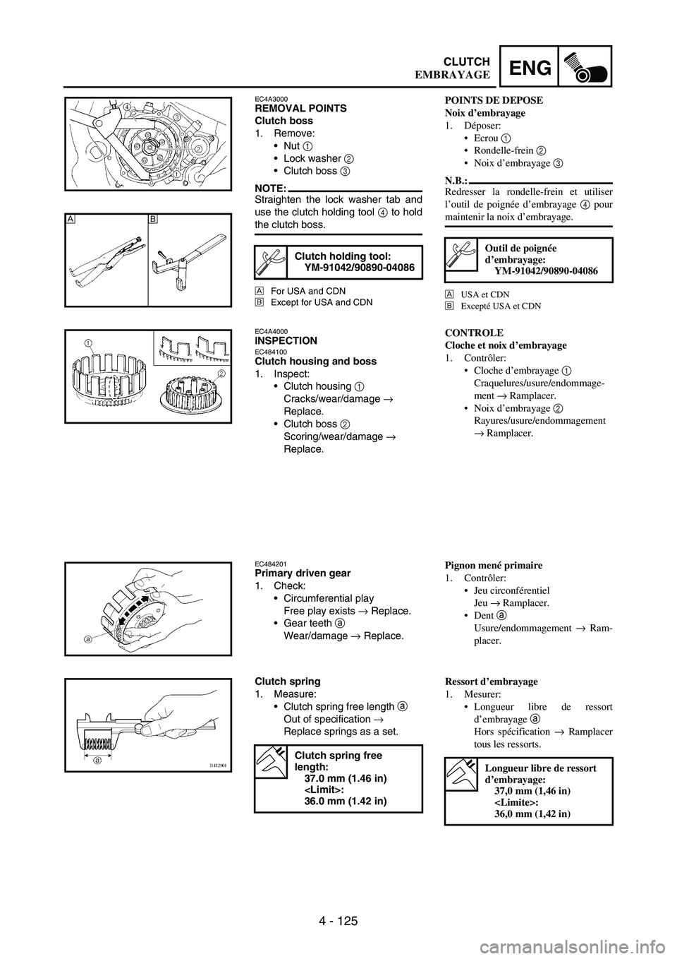
Clutch boss
1. Remove:
Nut
1
Lock washer
2
Clutch boss
3
NOTE:Straighten the lock washer tab and
use the clutch holding tool
4 to hold
the clutch boss.
ÈFor USA and CDN
ÉExcept for USA and CDN
Clutch holding tool:
YM-91042/90890-04086
ÈÉ
EC4A4000INSPECTIONEC484100Clutch housing and boss
1. Inspect:
Clutch housing
1
Cracks/wear/damage
→
Replace.
Clutch boss
2
Scoring/wear/damage
→
Replace.
EC484201Primary driven gear
1. Check:
Circumferential play
Free play exists
→ Replace.
Gear teeth
a
Wear/damage
→ Replace.
Clutch spring
1. Measure:
Clutch spring free length
a
Out of specification
→
Replace springs as a set.
Clutch spring free
length:
37.0 mm (1.46 in)
36.0 mm (1.42 in)
POINTS DE DEPOSE
Noix d’embrayage
1. Déposer:
Ecrou 1
Rondelle-frein 2
Noix d’embrayage 3
N.B.:
Redresser la rondelle-frein et utiliser
l’outil de poignée d’embrayage 4 pour
maintenir la noix d’embrayage.
È
USA et CDN
É
Excepté USA et CDN
Outil de poignée
d’embrayage:
YM-91042/90890-04086
CONTROLE
Cloche et noix d’embrayage
1. Contrôler:
Cloche d’embrayage 1
Craquelures/usure/endommage-
ment → Ramplacer.
Noix d’embrayage 2
Rayures/usure/endommagement
→ Ramplacer.
Pignon mené primaire
1. Contrôler:
Jeu circonférentiel
Jeu → Ramplacer.
Dent
a
Usure/endommagement → Ram-
placer.
Ressort d’embrayage
1. Mesurer:
Longueur libre de ressort
d’embrayage
a
Hors spécification → Ramplacer
tous les ressorts.
Longueur libre de ressort
d’embrayage:
37,0 mm (1,46 in)
36,0 mm (1,42 in)
EMBRAYAGE
Page 654 of 864
5 - 73
CHASFRONT FORK
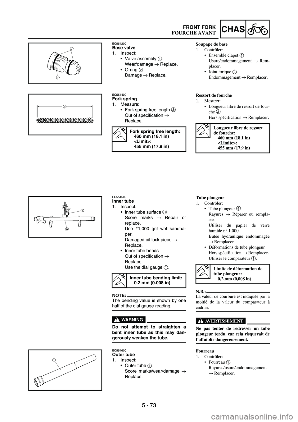
EC554200Base valve
1. Inspect:
Valve assembly
1
Wear/damage
→ Replace.
O-ring
2
Damage
→ Replace.
EC554400Fork spring
1. Measure:
Fork spring free length
a
Out of specification
→
Replace.
Fork spring free length:
460 mm (18.1 in)
455 mm (17.9 in)
EC554502Inner tube
1. Inspect:
Inner tube surface
a
Score marks
→ Repair or
replace.
Use #1,000 grit wet sandpa-
per.
Damaged oil lock piece
→
Replace.
Inner tube bends
Out of specification
→
Replace.
Use the dial gauge
1.
NOTE:The bending value is shown by one
half of the dial gauge reading.
WARNING
Do not attempt to straighten a
bent inner tube as this may dan-
gerously weaken the tube.
Inner tube bending limit:
0.2 mm (0.008 in)
EC554600Outer tube
1. Inspect:
Outer tube
1
Score marks/wear/damage
→
Replace.
Soupape de base
1. Contrôler:
Ensemble clapet 1
Usure/endommagement → Rem-
placer.
Joint torique 2
Endommagement → Remplacer.
Ressort de fourche
1. Mesurer:
Longueur libre de ressort de four-
che a
Hors spécification → Remplacer.
Longueur libre de ressort
de fourche:
460 mm (18,1 in)
455 mm (17,9 in)
Tube plongeur
1. Contrôler:
Tube plongeur a
Rayures → Réparer ou rempla-
cer.
Utiliser du papier de verre
humide n° 1.000.
Butée hydraulique endommagée
→ Remplacer.
Déformations de tube plongeur
Hors spécification → Remplacer.
Utiliser le comparateur 1.
N.B.:
La valeur de courbure est indiquée par la
moitié de la valeur du comparateur à
cadran.
AVERTISSEMENT
Ne pas tenter de redresser un tube
plongeur tordu, car cela risquerait de
l’affaiblir dangereusement.
Limite de déformation de
tube plongeur:
0,2 mm (0,008 in)
Fourreau
1. Contrôler:
Fourreau 1
Rayures/usure/endommagement
→ Remplacer.
FOURCHE AVANT
Page 734 of 864
5 - 153
CHASREAR SHOCK ABSORBER
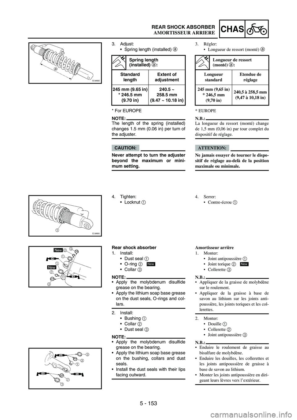
3. Adjust:
Spring length (installed)
a
* For EUROPE
NOTE:The length of the spring (installed)
changes 1.5 mm (0.06 in) per turn of
the adjuster.
CAUTION:
Never attempt to turn the adjuster
beyond the maximum or mini-
mum setting.
Spring length
(installed) a
:
Standard
lengthExtent of
adjustment
245 mm (9.65 in)
* 246.5 mm
(9.70 in)240.5 ~
258.5 mm
(9.47 ~ 10.18 in)
4. Tighten:
Locknut
1
Rear shock absorber
1. Install:
Dust seal
1
O-ring
2
Collar
3
NOTE:Apply the molybdenum disulfide
grease on the bearing.
Apply the lithium soap base grease
on the dust seals, O-rings and col-
lars.
2. Install:
Bushing
1
Collar
2
Dust seal
3
NOTE:Apply the molybdenum disulfide
grease on the bearing.
Apply the lithium soap base grease
on the bushing, collars and dust
seals.
Install the dust seals with their lips
facing outward.
New
3. Régler:
Longueur de ressort (monté) a
* EUROPE
N.B.:
La longueur du ressort (monté) change
de 1,5 mm (0,06 in) par tour complet du
dispositif de réglage.
ATTENTION:
Ne jamais essayer de tourner le dispo-
sitif de réglage au-delà de la position
maximale ou minimale.
Longueur de ressort
(monté) a:
Longueur
standardEtendue de
réglage
245 mm (9,65 in)
* 246,5 mm
(9,70 in)240,5 à 258,5 mm
(9,47 à 10,18 in)
4. Serrer:
Contre-écrou 1
Amortisseur arrière
1. Monter:
Joint antipoussière 1
Joint torique 2
Collerette 3
N.B.:
Appliquer de la graisse de molybdène
sur le roulement.
Appliquer de la graisse à base de
savon au lithium sur les joints anti-
poussière, les joints toriques et les col-
lerettes.
2. Monter:
Douille 1
Collerette 2
Joint antipoussière 3
N.B.:
Enduire le roulement de graisse au
bisulfure de molybdène.
Enduire les douilles, les collerettes et
les joints antipoussière de graisse à
base de savon au lithium.
Monter les joints antipoussière en diri-
geant leurs lèvres vers l’extérieur.
New
AMORTISSEUR ARRIERE
Page 778 of 864
6 - 41
–+ELECELECTRIC STARTING SYSTEM
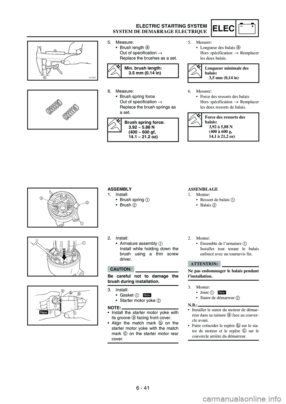
5. Measure:
Brush length
a
Out of specification
→
Replace the brushes as a set.
Min. brush length:
3.5 mm (0.14 in)
6. Measure:
Brush spring force
Out of specification
→
Replace the brush springs as
a set.
Brush spring force:
3.92 ~ 5.88 N
(400 ~ 600 gf,
14.1 ~ 21.2 oz)
ASSEMBLY
1. Install:
Brush spring
1
Brush
2
2. Install:
Armature assembly
1
Install while holding down the
brush using a thin screw
driver.
CAUTION:
Be careful not to damage the
brush during installation.
3. Install:
Gasket
1
Starter motor yoke
2
NOTE:Install the starter motor yoke with
its groove
a facing front cover.
Align the match mark
b on the
starter motor yoke with the match
mark
c on the starter motor rear
cover.
New
5. Mesurer:
Longueur des balais a
Hors spécification → Remplacer
les deux balais.
Longueur minimale des
balais:
3,5 mm (0,14 in)
6. Mesurer:
Force des ressorts des balais
Hors spécification → Remplacer
les deux ressorts de balais.
Force des ressorts des
balais:
3,92 à 5,88 N
(400 à 600 g,
14,1 à 21,2 oz)
ASSEMBLAGE
1. Monter:
Ressort de balais 1
Balais 2
2. Monter:
Ensemble de l’armature 1
Installer tout tenant le balais
enfoncé avec un tournevis fin.
ATTENTION:
Ne pas endommager le balais pendant
l’installation.
3. Monter:
Joint 1
Stator de démarreur 2
N.B.:
Installer le stator du moteur de démar-
reur dans sa rainure a face au couver-
cle avant.
Faire coïncider le repère b sur le sta-
tor de moteur et le repère c sur le
couvercle arrière du démarreur.
New
SYSTEM DE DEMARRAGE ELECTRIQUE
Page 846 of 864
7 - 35
TUNSETTING
EC72B000Rear suspension setting
The rear suspension setting should
be made depending on the rider’s
feeling of an actual run and the cir-
cuit conditions.
The rear suspension setting includes
the following two factors:
1. Setting of spring preload
Change the set length of the
spring.
Change the spring.
2. Setting of damping force
Change the rebound damping.
Change the compression
damping.
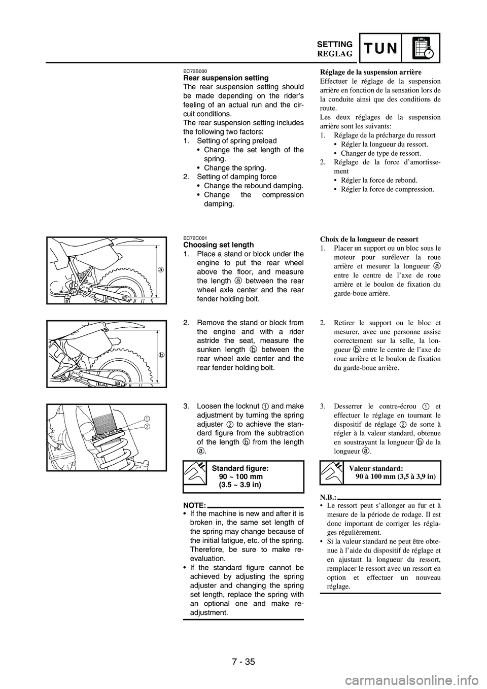
EC72C001Choosing set length
1. Place a stand or block under the
engine to put the rear wheel
above the floor, and measure
the length
a between the rear
wheel axle center and the rear
fender holding bolt.
2. Remove the stand or block from
the engine and with a rider
astride the seat, measure the
sunken length
b between the
rear wheel axle center and the
rear fender holding bolt.
3. Loosen the locknut
1 and make
adjustment by turning the spring
adjuster
2 to achieve the stan-
dard figure from the subtraction
of the length
b from the length
a.
NOTE:If the machine is new and after it is
broken in, the same set length of
the spring may change because of
the initial fatigue, etc. of the spring.
Therefore, be sure to make re-
evaluation.
If the standard figure cannot be
achieved by adjusting the spring
adjuster and changing the spring
set length, replace the spring with
an optional one and make re-
adjustment.
Standard figure:
90 ~ 100 mm
(3.5 ~ 3.9 in)
Réglage de la suspension arrière
Effectuer le réglage de la suspension
arrière en fonction de la sensation lors de
la conduite ainsi que des conditions de
route.
Les deux réglages de la suspension
arrière sont les suivants:
1. Réglage de la précharge du ressort
Régler la longueur du ressort.
Changer de type de ressort.
2. Réglage de la force d’amortisse-
ment
Régler la force de rebond.
Régler la force de compression.
Choix de la longueur de ressort
1. Placer un support ou un bloc sous le
moteur pour surélever la roue
arrière et mesurer la longueur a
entre le centre de l’axe de roue
arrière et le boulon de fixation du
garde-boue arrière.
2. Retirer le support ou le bloc et
mesurer, avec une personne assise
correctement sur la selle, la lon-
gueur b entre le centre de l’axe de
roue arrière et le boulon de fixation
du garde-boue arrière.
3. Desserrer le contre-écrou 1 et
effectuer le réglage en tournant le
dispositif de réglage 2 de sorte à
régler à la valeur standard, obtenue
en soustrayant la longueur b de la
longueur a.
N.B.:
Le ressort peut s’allonger au fur et à
mesure de la période de rodage. Il est
donc important de corriger les régla-
ges régulièrement.
Si la valeur standard ne peut être obte-
nue à l’aide du dispositif de réglage et
en ajustant la longueur du ressort,
remplacer le ressort avec un ressort en
option et effectuer un nouveau
réglage.
Valeur standard:
90 à 100 mm (3,5 à 3,9 in)
REGLAG
Page 848 of 864
![YAMAHA WR 250F 2004 User Guide 7 - 37
TUNSETTING
Setting of spring after
replacement
After replacement, be sure to adjust
the spring to the set length [sunken
length 90 ~ 100 mm (3.5 ~ 3.9 in)]
and set it.
1. Use of soft spring
S YAMAHA WR 250F 2004 User Guide 7 - 37
TUNSETTING
Setting of spring after
replacement
After replacement, be sure to adjust
the spring to the set length [sunken
length 90 ~ 100 mm (3.5 ~ 3.9 in)]
and set it.
1. Use of soft spring
S](/img/51/52336/w960_52336-847.png)
7 - 37
TUNSETTING
Setting of spring after
replacement
After replacement, be sure to adjust
the spring to the set length [sunken
length 90 ~ 100 mm (3.5 ~ 3.9 in)]
and set it.
1. Use of soft spring
Set the soft spring for less
rebound damping to compen-
sate for its less spring load.
Run with the rebound damping
adjuster one or two clicks on
the softer side and readjust it
to suit your preference.
2. Use of stiff spring
Set the soft spring for more
rebound damping to compen-
sate for its greater spring load.
Run with the rebound damping
adjuster one or two clicks on
the stiffer side and readjust it
to suit your preference.
*Adjusting the rebound damp-
ing will be followed more or
less by a change in the com-
pression damping. For correc-
tion, turn the low compression
damping adjuster on the softer
side.
CAUTION:
When using a rear shock absorber
other than currently installed, use
the one whose overall length a
does not exceed the standard as it
may result in faulty performance.
Never use one whose overall
length is greater than standard.
È
Coverage of spring by weight
É
Rider weight
1Soft
2Standard
3Stiff
Length a
of standard
shock:
490.5 mm (19.31 in)
Réglage du ressort après
remplacement
Après avoir remplacé le ressort, veiller à
ajuster celui-ci à la longueur recomman-
dée [profondeur 90 à 100 mm (3,5 à
3,9 in)] et à le régler.
1. Ressort mou
Régler le ressort doux de sorte à
ce que la force de rebond soit
moindre puisque la charge du res-
sort sera moindre. Rouler après
avoir dévissé le dispositif de
réglage de la force de rebond
d’un ou deux déclics et ajuster
ensuite selon ses préférences.
2. Ressort dur
Régler le ressort dur de sorte à ce
que la force de rebond soit plus
élevée afin de compenser la
charge du ressort plus grande.
Rouler après avoir vissé le dispo-
sitif de réglage de la force de
rebond d’un ou deux déclics et
ajuster ensuite selon ses préféren-
ces.
*Un réglage de la force de rebond
entraîne un changement de la
force de compression. Pour com-
penser, dévisser le dispositif de
réglage de la force de compres-
sion.
ATTENTION:
Lors du remplacement de l’amortis-
seur arrière, veiller à monter un
amortisseur dont la longueur totale a
n’excède pas la longueur standard
sinon, il y a risque de mauvaises per-
formances. Ne jamais monter un
amortisseur dont la longueur totale est
supérieure à la longueur standard.
È
Ressort recommandé en fonction du
poids
É
Poids du motocycliste
1
Mou
2
Standard
3
Dur
Longueur standard a
d’amatisseur arrière:
490,5 mm (19,31 in)
REGLAG
Page 850 of 864
![YAMAHA WR 250F 2004 User Guide 7 - 39
TUNSETTING
EC72Q000Rear shock absorber setting parts
Rear shock spring
1
[Equal pitch spring]
* For EUROPE
[Unequal pitch spring]
NOTE:The unequal pitch spring is softer
in initial characte YAMAHA WR 250F 2004 User Guide 7 - 39
TUNSETTING
EC72Q000Rear shock absorber setting parts
Rear shock spring
1
[Equal pitch spring]
* For EUROPE
[Unequal pitch spring]
NOTE:The unequal pitch spring is softer
in initial characte](/img/51/52336/w960_52336-849.png)
7 - 39
TUNSETTING
EC72Q000Rear shock absorber setting parts
Rear shock spring
1
[Equal pitch spring]
* For EUROPE
[Unequal pitch spring]
NOTE:The unequal pitch spring is softer
in initial characteristic than the
equal pitch spring and is difficult to
bottom out under full compression.
The I.D. color
a is marked at the
end of the spring.
Extent of adjustment
(spring length)
TYPESPRING
RATESPRING
PART
NUMBERI.D.
COLOR/
POINTSPRING
FREE
LENGTH
SOFT4.3
4.55UN-22212-00
5UN-22212-10Brown/1
Green/1260
260
* STD 4.7 5UN-22212-20 Red/1 260
4.9 5UN-22212-30 Black/1 260
STD 5.1 5UN-22212-40 Blue/1 260
STIFF5.3
5.5
5.75UN-22212-50
5UN-22212-60
5UN-22212-70Yellow/1
Pink/1
White/1260
260
260
TYPE
SPRING
RATE
(approx.)SPRING
PART
NUMBERI.D.
COLOR/
POINTSPRING
FREE
LENGTH
SOFT
STIFF4.5
4.7
4.9
5.1
5.3
5.5
5.75UN-22212-A0
5UN-22212-B0
5UN-22212-C0
5UN-22212-D0
5UN-22212-E0
5UN-22212-F0
5UN-22212-G0
Green/2
Red/2
Black/2
Blue/2
Yellow/2
Pink/2
White/2275
275
275
275
275
275
275
SPRING FREE
LENGTHEXTENT OF
ADJUSTMENT
b
260 mm
(10.24 in)
240.5 ~ 258.5 mm
(9.47 ~ 10.18 in)
275 mm
(10.83 in)255.5 ~ 273.5 mm
(10.06 ~ 10.77 in)
Pièces de réglage de l’amortisseur
arrière
Ressort d’amortisseur arrière 1
[Ressort à pas égal]
* EUROPE
[Ressort à pas inégal]
N.B.:
Le ressort à pas inégal est plus souple
suivant les caractéristiques initiales
que le ressort à pas égal et atteind dif-
ficilement son niveau le plus bas sous
une compression totable.
Le repère de couleur a est indiquée à
l’extrémité du ressort.
Longueur de réglage
(longueur de ressort)
TypeConstante
du ressortNuméro de pièce
de ressortRepere de
couleur/
pointLongueur
de ressort
MOU4,3
4,55UN-22212-00
5UN-22212-10Brun/1
Vert/1260
260
* STD 4,7 5UN-22212-20 Rouge/1 260
4,9 5UN-22212-30 Noir/1 260
STD5,1 5UN-22212-40 Bleu/1 260
DUR5,3
5,5
5,75UN-22212-50
5UN-22212-60
5UN-22212-70Jaune/1
Rose/1
Blanc/1260
260
260
Type
Constante
du ressort
(approx.)Numéro de pièce
de ressortRepere de
couleur/
pointLongueur
de ressort
MOU
DUR4,5
4,7
4,9
5,1
5,3
5,5
5,75UN-22212-A0
5UN-22212-B0
5UN-22212-C0
5UN-22212-D0
5UN-22212-E0
5UN-22212-F0
5UN-22212-G0Vert/2
Rouge/2
Noir/2
Bleu/2
Jaune/2
Rose/2
Blanc/2275
275
275
275
275
275
275
LONGUEUR DE
RESSORT
LIBRELONGUEUR DE
REGLAGE b
260 mm (10,24 in)240,5 à 258,5 mm
(9,47 à 10,18 in)
275 mm (10,83 in)255,5 à 273,5 mm
(10,06 à 10,77 in)
REGLAG