Carburetor YAMAHA WR 250F 2006 Owner's Manual
[x] Cancel search | Manufacturer: YAMAHA, Model Year: 2006, Model line: WR 250F, Model: YAMAHA WR 250F 2006Pages: 900, PDF Size: 23.77 MB
Page 378 of 900
4 - 37
ENGCARBURETOR
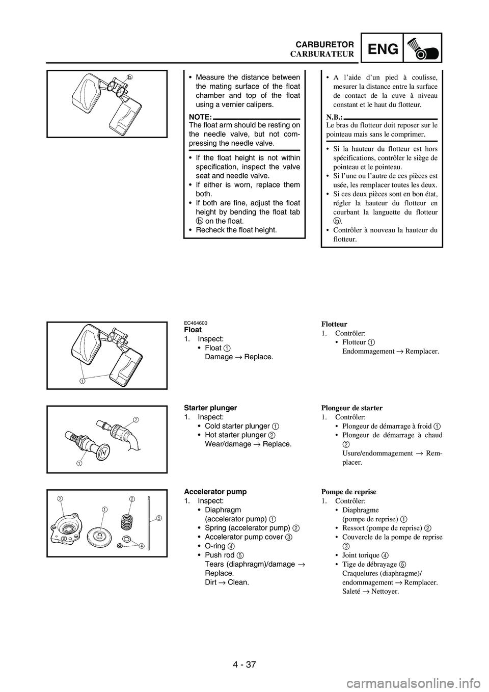
Measure the distance between
the mating surface of the float
chamber and top of the float
using a vernier calipers.
NOTE:The float arm should be resting on
the needle valve, but not com-
pressing the needle valve.
If the float height is not within
specification, inspect the valve
seat and needle valve.
If either is worn, replace them
both.
If both are fine, adjust the float
height by bending the float tab
b on the float.
Recheck the float height.
EC464600Float
1. Inspect:
Float
1
Damage
→ Replace.
Starter plunger
1. Inspect:
Cold starter plunger
1
Hot starter plunger
2
Wear/damage
→ Replace.
Accelerator pump
1. Inspect:
Diaphragm
(accelerator pump)
1
Spring (accelerator pump)
2
Accelerator pump cover
3
O-ring
4
Push rod
5
Tears (diaphragm)/damage
→
Replace.
Dirt
→ Clean.
A l’aide d’un pied à coulisse,
mesurer la distance entre la surface
de contact de la cuve à niveau
constant et le haut du flotteur.
N.B.:
Le bras du flotteur doit reposer sur le
pointeau mais sans le comprimer.
Si la hauteur du flotteur est hors
spécifications, contrôler le siège de
pointeau et le pointeau.
Si l’une ou l’autre de ces pièces est
usée, les remplacer toutes les deux.
Si ces deux pièces sont en bon état,
régler la hauteur du flotteur en
courbant la languette du flotteur
b.
Contrôler à nouveau la hauteur du
flotteur.
Flotteur
1. Contrôler:
Flotteur 1
Endommagement → Remplacer.
Plongeur de starter
1. Contrôler:
Plongeur de démarrage à froid 1
Plongeur de démarrage à chaud
2
Usure/endommagement → Rem-
placer.
Pompe de reprise
1. Contrôler:
Diaphragme
(pompe de reprise) 1
Ressort (pompe de reprise) 2
Couvercle de la pompe de reprise
3
Joint torique 4
Tige de débrayage 5
Craquelures (diaphragme)/
endommagement → Remplacer.
Saleté → Nettoyer.
CARBURATEUR
Page 380 of 900
4 - 39
ENGCARBURETOR
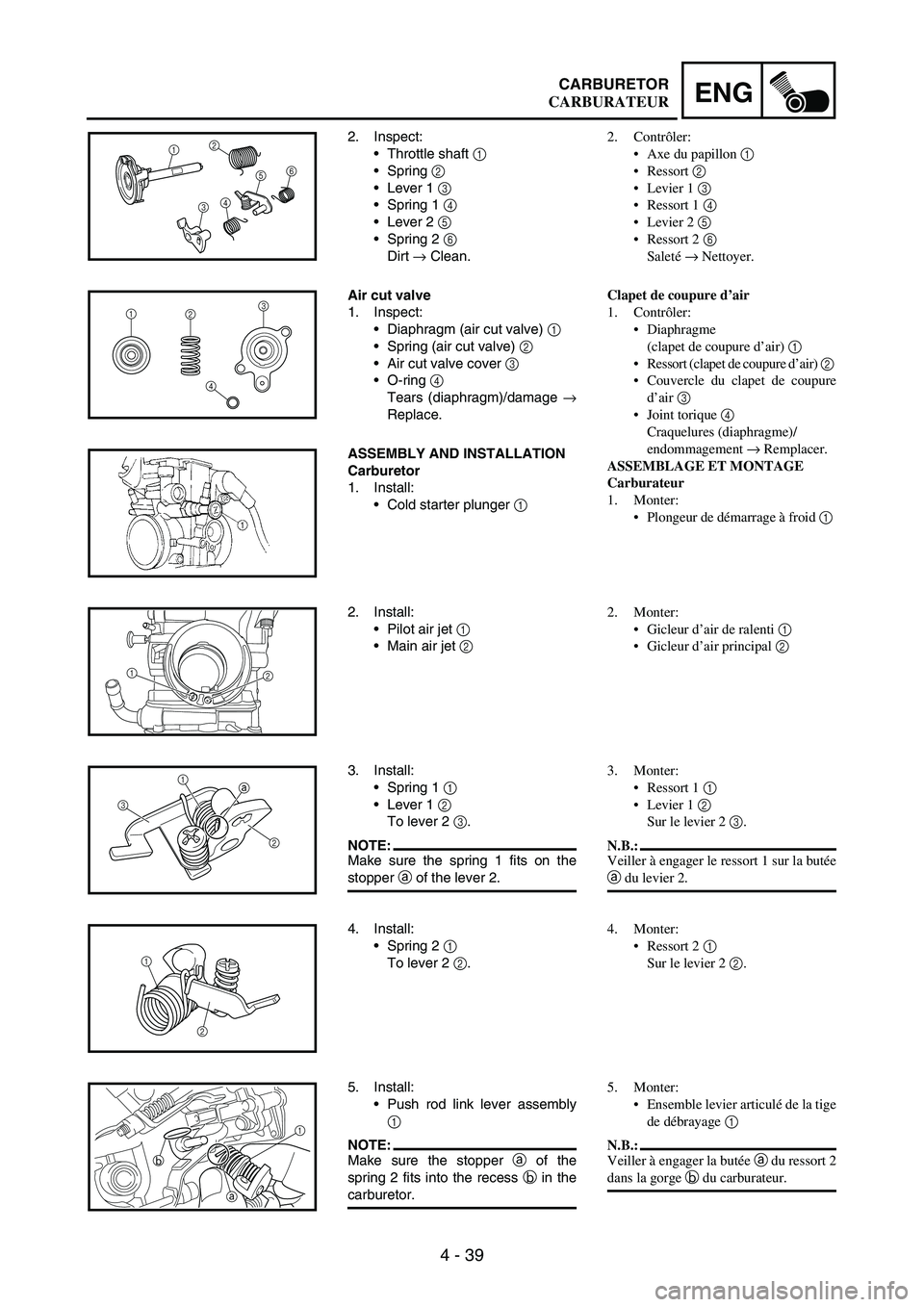
2. Inspect:
Throttle shaft
1
Spring
2
Lever 1
3
Spring 1
4
Lever 2
5
Spring 2
6
Dirt
→ Clean.12
3456
Air cut valve
1. Inspect:
Diaphragm (air cut valve)
1
Spring (air cut valve)
2
Air cut valve cover
3
O-ring
4
Tears (diaphragm)/damage
→
Replace.
1
23
4
ASSEMBLY AND INSTALLATION
Carburetor
1. Install:
Cold starter plunger
1
2. Install:
Pilot air jet
1
Main air jet
2
12
3. Install:
Spring 1
1
Lever 1
2
To lever 2
3.
NOTE:Make sure the spring 1 fits on the
stopper
a of the lever 2.
a
31
2
4. Install:
Spring 2 1
To lever 2 2.
1
2
5. Install:
Push rod link lever assembly
1
NOTE:Make sure the stopper a of the
spring 2 fits into the recess b in the
carburetor.
1
a b
2. Contrôler:
Axe du papillon 1
Ressort 2
Levier 1 3
Ressort 1 4
Levier 2 5
Ressort 2 6
Saleté → Nettoyer.
Clapet de coupure d’air
1. Contrôler:
Diaphragme
(clapet de coupure d’air) 1
Ressort (clapet de coupure d’air) 2
Couvercle du clapet de coupure
d’air 3
Joint torique 4
Craquelures (diaphragme)/
endommagement → Remplacer.
ASSEMBLAGE ET MONTAGE
Carburateur
1. Monter:
Plongeur de démarrage à froid 1
2. Monter:
Gicleur d’air de ralenti 1
Gicleur d’air principal 2
3. Monter:
Ressort 1 1
Levier 1 2
Sur le levier 2 3.
N.B.:
Veiller à engager le ressort 1 sur la butée
a du levier 2.
4. Monter:
Ressort 2 1
Sur le levier 2 2.
5. Monter:
Ensemble levier articulé de la tige
de débrayage 1
N.B.:
Veiller à engager la butée a du ressort 2
dans la gorge b du carburateur.
CARBURATEUR
Page 382 of 900

4 - 41
ENGCARBURETOR
6. Install:
Washer
1
Circlip
2
21
7. Install:
Spring
1
To throttle shaft
2.
NOTE:Install the bigger hook
a of the
spring fits on the stopper b of the
throttle shaft pulley.
8. Install:
Throttle shaft assembly 1
Washer (metal) 2
Washer (resin) 3
Valve lever 4
NOTE:Apply the fluorochemical grease
on the bearings.
Fit the projection a on the throttle
shaft assembly into the slot b in
the throttle position sensor.
Make sure the stopper c of the
spring fits into the recess in the
carburetor.
Turn the throttle shaft assembly
left while holding down the lever 1
5 and fit the throttle stop screw tip
d to the stopper e of the throttle
shaft assembly pulley.
1
23
4
b
a
c
e
d
5
9. Install:
Push rod 1
NOTE:While holding down the lever 1 2,
insert the push rod farthest into the
carburetor.
12
10. Install:
Starter jet 1
Pilot jet 2
Spacer 3
Needle jet 4
Main jet 5
6. Monter:
Rondelle 1
Circlip 2
7. Monter:
Ressort 1
Sur l’axe du papillon 2.
N.B.:
Monter le plus grand crochet a du res-
sort sur la butée b de la poulie de l’axe
de papillon.
8. Monter:
Axe du papillon complet 1
Rondelle (métallique) 2
Rondelle (résine) 3
Levier de soupape 4
N.B.:
Appliquer de la graisse à base de com-
posé fluoré sur les paliers.
Engager l’ergot a de l’ensemble axe
de papillon dans la fente b du capteur
de position de papillon des gaz.
Veiller à engager la butée c du res-
sort dans la gorge du carburateur.
Tourner l’ensemble axe de papillon
vers la gauche tout en maintenant le
levier 1 5 abaissé et engager la pointe
de la vis de butée de papillon des gaz
d sur la butée e de la poulie de
l’ensemble axe de papillon.
9. Monter:
Tige de débrayage 1
N.B.:
Tout en maintenant abaissé le levier 1
2, insérer la tige de débrayage plus
avant dans le carburateur.
10. Monter:
Gicleur de starter 1
Gicleur de ralenti 2
Entretoise 3
Gicleur d’aiguille 4
Gicleur principal 5
CARBURATEUR
Page 384 of 900
4 - 43
ENGCARBURETOR
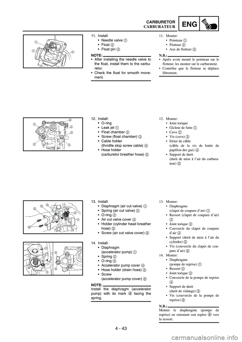
11. Install:
Needle valve
1
Float
2
Float pin
3
NOTE:After installing the needle valve to
the float, install them to the carbu-
retor.
Check the float for smooth move-
ment.
12. Install:
O-ring
Leak jet
1
Float chamber
2
Screw (float chamber)
3
Cable holder
(throttle stop screw cable)
4
Hose holder
(carburetor breather hose)
5
13. Install:
Diaphragm (air cut valve)
1
Spring (air cut valve)
2
O-ring
3
Air cut valve cover
4
Holder (cylinder head breather
hose)
5
Screw (air cut valve cover)
6
653
4
1 2
14. Install:
Diaphragm
(accelerator pump)
1
Spring
2
O-ring
3
Accelerator pump cover
4
Hose holder (drain hose)
5
Screw
(accelerator pump cover)
6
NOTE:Install the diaphragm (accelerator
pump) with its mark
a facing the
spring.
11. Monter:
Pointeau 1
Flotteur 2
Axe de flotteur 3
N.B.:
Après avoir monté le pointeau sur le
flotteur, les monter sur le carburateur.
Contrôler que le flotteur se déplace
librement.
12. Monter:
Joint torique
Gicleur de fuite 1
Cuve 2
Vis (cuve) 3
Etrier de câble
(câble de la vis de butée de
papillon des gaz) 4
Support de durit
(durit de mise à l’air du carbura-
teur) 5
13. Monter:
Diaphragme
(clapet de coupure d’air) 1
Ressort (clapet de coupure d’air)
2
Joint torique 3
Couvercle du clapet de coupure
d’air 4
Support (durit de mise à l’air du
cylindre) 5
Vis (couvercle du clapet de cou-
pure d’air) 6
14. Monter:
Diaphragme
(pompe de reprise) 1
Ressort 2
Joint torique 3
Couvercle de la pompe de reprise
4
Support de durit
(durit de vidange) 5
Vis (couvercle de la pompe de
reprise) 6
N.B.:
Monter le diaphragme (pompe de
reprise) en orientant son repère a vers
le ressort.
CARBURATEUR
Page 386 of 900
4 - 45
ENGCARBURETOR
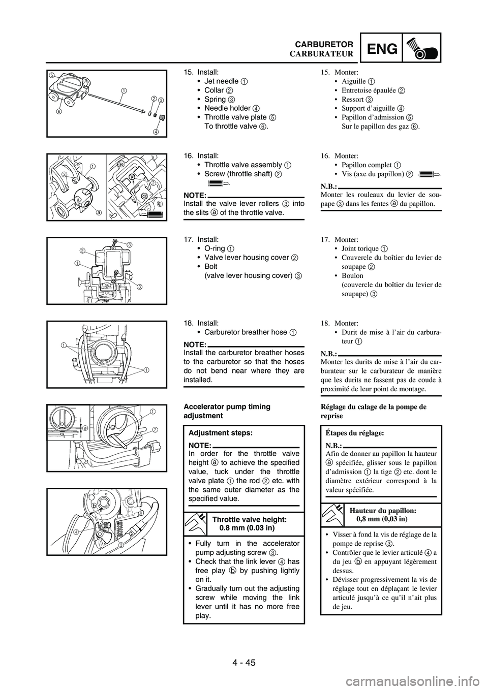
15. Install:
Jet needle
1
Collar
2
Spring
3
Needle holder
4
Throttle valve plate
5
To throttle valve
6.5
6
1
2
3
4
16. Install:
Throttle valve assembly
1
Screw (throttle shaft)
2
NOTE:Install the valve lever rollers
3 into
the slits
a of the throttle valve.
17. Install:
O-ring 1
Valve lever housing cover 2
Bolt
(valve lever housing cover) 3
18. Install:
Carburetor breather hose 1
NOTE:Install the carburetor breather hoses
to the carburetor so that the hoses
do not bend near where they are
installed.
Accelerator pump timing
adjustment
Adjustment steps:
NOTE:In order for the throttle valve
height a to achieve the specified
value, tuck under the throttle
valve plate 1 the rod 2 etc. with
the same outer diameter as the
specified value.
Throttle valve height:
0.8 mm (0.03 in)
Fully turn in the accelerator
pump adjusting screw 3.
Check that the link lever 4 has
free play b by pushing lightly
on it.
Gradually turn out the adjusting
screw while moving the link
lever until it has no more free
play.
15. Monter:
Aiguille 1
Entretoise épaulée 2
Ressort 3
Support d’aiguille 4
Papillon d’admission 5
Sur le papillon des gaz 6.
16. Monter:
Papillon complet 1
Vis (axe du papillon) 2
N.B.:
Monter les rouleaux du levier de sou-
pape 3 dans les fentes a du papillon.
17. Monter:
Joint torique 1
Couvercle du boîtier du levier de
soupape 2
Boulon
(couvercle du boîtier du levier de
soupape) 3
18. Monter:
Durit de mise à l’air du carbura-
teur 1
N.B.:
Monter les durits de mise à l’air du car-
burateur sur le carburateur de manière
que les durits ne fassent pas de coude à
proximité de leur point de montage.
Réglage du calage de la pompe de
reprise
Étapes du réglage:
N.B.:
Afin de donner au papillon la hauteur
a spécifiée, glisser sous le papillon
d’admission 1 la tige 2 etc. dont le
diamètre extérieur correspond à la
valeur spécifiée.
Hauteur du papillon:
0,8 mm (0,03 in)
Visser à fond la vis de réglage de la
pompe de reprise 3.
Contrôler que le levier articulé 4 a
du jeu b en appuyant légèrement
dessus.
Dévisser progressivement la vis de
réglage tout en déplaçant le levier
articulé jusqu’à ce qu’il n’ait plus
de jeu.
CARBURATEUR
Page 388 of 900
4 - 47
ENGCARBURETOR
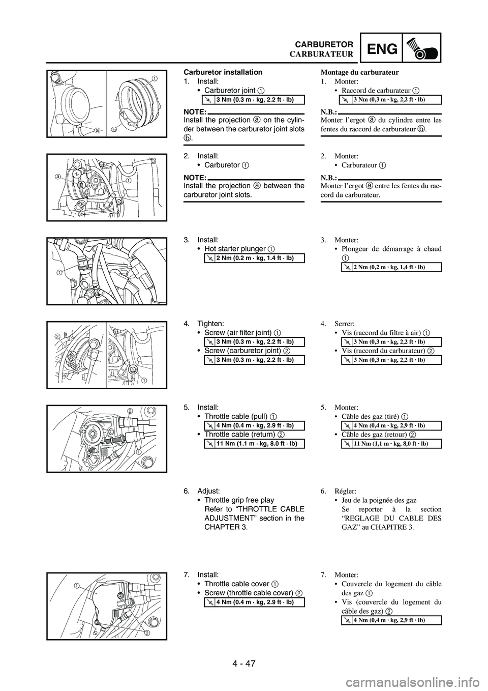
Carburetor installation
1. Install:
Carburetor joint
1
NOTE:Install the projection
a on the cylin-
der between the carburetor joint slots
b.
T R..3 Nm (0.3 m · kg, 2.2 ft · lb)
2. Install:
Carburetor
1
NOTE:Install the projection
a between the
carburetor joint slots.
3. Install:
Hot starter plunger
1
T R..2 Nm (0.2 m · kg, 1.4 ft · lb)
1
4. Tighten:
Screw (air filter joint)
1
Screw (carburetor joint)
2
T R..3 Nm (0.3 m · kg, 2.2 ft · lb)
T R..3 Nm (0.3 m · kg, 2.2 ft · lb)
5. Install:
Throttle cable (pull) 1
Throttle cable (return) 2
T R..4 Nm (0.4 m · kg, 2.9 ft · lb)
T R..11 Nm (1.1 m · kg, 8.0 ft · lb)
2
1
6. Adjust:
Throttle grip free play
Refer to “THROTTLE CABLE
ADJUSTMENT” section in the
CHAPTER 3.
7. Install:
Throttle cable cover 1
Screw (throttle cable cover) 2
T R..4 Nm (0.4 m · kg, 2.9 ft · lb)
2 1
Montage du carburateur
1. Monter:
Raccord de carburateur 1
N.B.:
Monter l’ergot a du cylindre entre les
fentes du raccord de carburateur b.
T R..3 Nm (0,3 m · kg, 2,2 ft · lb)
2. Monter:
Carburateur 1
N.B.:
Monter l’ergot a entre les fentes du rac-
cord du carburateur.
3. Monter:
Plongeur de démarrage à chaud
1
T R..2 Nm (0,2 m · kg, 1,4 ft · lb)
4. Serrer:
Vis (raccord du filtre à air) 1
Vis (raccord du carburateur) 2
T R..3 Nm (0,3 m · kg, 2,2 ft · lb)
T R..3 Nm (0,3 m · kg, 2,2 ft · lb)
5. Monter:
Câble des gaz (tiré) 1
Câble des gaz (retour) 2
T R..4 Nm (0,4 m · kg, 2,9 ft · lb)
T R..11 Nm (1,1 m · kg, 8,0 ft · lb)
6. Régler:
Jeu de la poignée des gaz
Se reporter à la section
“REGLAGE DU CABLE DES
GAZ” au CHAPITRE 3.
7. Monter:
Couvercle du logement du câble
des gaz 1
Vis (couvercle du logement du
câble des gaz) 2
T R..4 Nm (0,4 m · kg, 2,9 ft · lb)
CARBURATEUR
Page 390 of 900

4 - 49
ENGCARBURETOR
8. Install:
Throttle position sensor lead
coupler
1
Clamp
2
Refer to “CABLE ROUTING
DIAGRAM” section in the
CHAPTER 2.
9. Install:
Clamp
1
Refer to “CABLE ROUTING
DIAGRAM” section in the
CHAPTER 2.
1
8. Monter:
Fiche rapide du fil du capteur de
position de papillon des gaz 1
Collier 2
Se reporter à la section “CHEMI-
NEMENT DES CABLES” au
CHAPITRE 2.
9. Monter:
Collier 1
Se reporter à la section “CHEMI-
NEMENT DES CABLES” au
CHAPITRE 2.
CARBURATEUR
Page 398 of 900
4 - 57
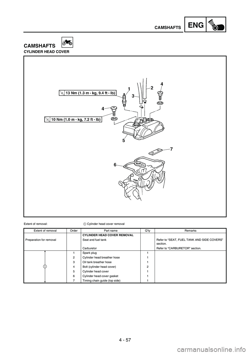
ENGCAMSHAFTS
CAMSHAFTS
CYLINDER HEAD COVER
Extent of removal:
1 Cylinder head cover removal
Extent of removal Order Part name Q’ty Remarks
CYLINDER HEAD COVER REMOVAL
Preparation for removal Seat and fuel tank Refer to “SEAT, FUEL TANK AND SIDE COVERS”
section.
Carburetor Refer to “CARBURETOR” section.
1 Spark plug 1
2 Cylinder head breather hose 1
3 Oil tank breather hose 1
4 Bolt (cylinder head cover) 2
5 Cylinder head cover 1
6 Cylinder head cover gasket 1
7 Timing chain guide (top side) 1
1
Page 420 of 900
4 - 79
ENGCYLINDER HEAD
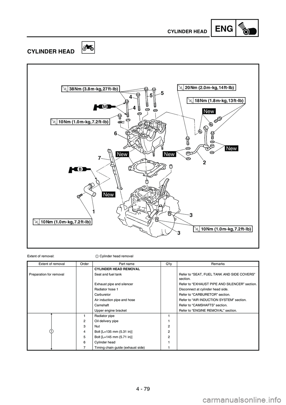
CYLINDER HEAD
Extent of removal:
1 Cylinder head removal
Extent of removal Order Part name Q’ty Remarks
CYLINDER HEAD REMOVAL
Preparation for removal Seat and fuel tank Refer to “SEAT, FUEL TANK AND SIDE COVERS”
section.
Exhaust pipe and silencer Refer to “EXHAUST PIPE AND SILENCER” section.
Radiator hose 1 Disconnect at cylinder head side.
Carburetor Refer to “CARBURETOR” section.
Air induction pipe and hose Refer to “AIR INDUCTION SYSTEM” section.
Camshaft Refer to “CAMSHAFTS” section.
Upper engine bracket Refer to “ENGINE REMOVAL” section.
1 Radiator pipe 1
2 Oil delivery pipe 1
3Nut 2
4 Bolt [L=135 mm (5.31 in)] 2
5 Bolt [L=145 mm (5.71 in)] 2
6 Cylinder head 1
7 Timing chain guide (exhaust side) 1
1
Page 556 of 900
4 - 215
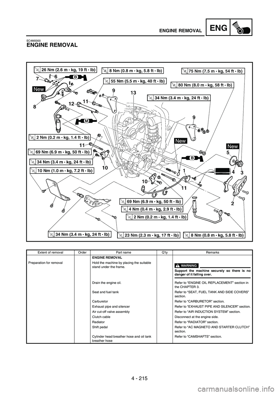
ENGENGINE REMOVAL
EC4M0000
ENGINE REMOVAL
Extent of removal Order Part name Q’ty Remarks
ENGINE REMOVAL
Preparation for removal Hold the machine by placing the suitable
stand under the frame.
WARNING
Support the machine securely so there is nodanger of it falling over.
Drain the engine oil. Refer to “ENGINE OIL REPLACEMENT” section in
the CHAPTER 3.
Seat and fuel tank Refer to “SEAT, FUEL TANK AND SIDE COVERS”
section.
Carburetor Refer to “CARBURETOR” section.
Exhaust pipe and silencer Refer to “EXHAUST PIPE AND SILENCER” section.
Air cut-off valve assembly Refer to “AIR INDUCTION SYSTEM” section.
Clutch cable Disconnect at the engine side.
Radiator Refer to “RADIATOR” section.
Shift pedal Refer to “AC MAGNETO AND STARTER CLUTCH”
section.
Cylinder head breather hose and oil tank
breather hoseRefer to “CAMSHAFTS” section.