Carburetor YAMAHA WR 250F 2006 User Guide
[x] Cancel search | Manufacturer: YAMAHA, Model Year: 2006, Model line: WR 250F, Model: YAMAHA WR 250F 2006Pages: 900, PDF Size: 23.77 MB
Page 196 of 900

SPEC
2 - 103
CABLE ROUTING DIAGRAM
1Hot starter cable
2Throttle cable (return)
3Throttle cable (pull)
4Cable guide
5Ignition coil
6Coolant reservoir breather hose
7Coolant reservoir hose
8Clamp
9CDI unit lead
0CDI unit
ACDI unit band
BCDI unit stayÈPass the throttle cables and hot starter cable through the cable
guides.
ÉPass the throttle cables and hot starter cable between the radi-
ator and frame, then under the radiator mounting boss.
ÊPass the throttle cables on the outside of the ignition coil.
ËPass the carburetor breather hose (of the throttle cable cover)
through the hose holder.
ÌFasten the coolant reservoir breather hose and carburetor
breather hoses together.
A B
0
A
0
891
32
4
É
Ê
5
67
Ë ÌÎ
ÍÈ
Page 209 of 900

3 - 2
INSP
ADJ
MAINTENANCE INTERVALS
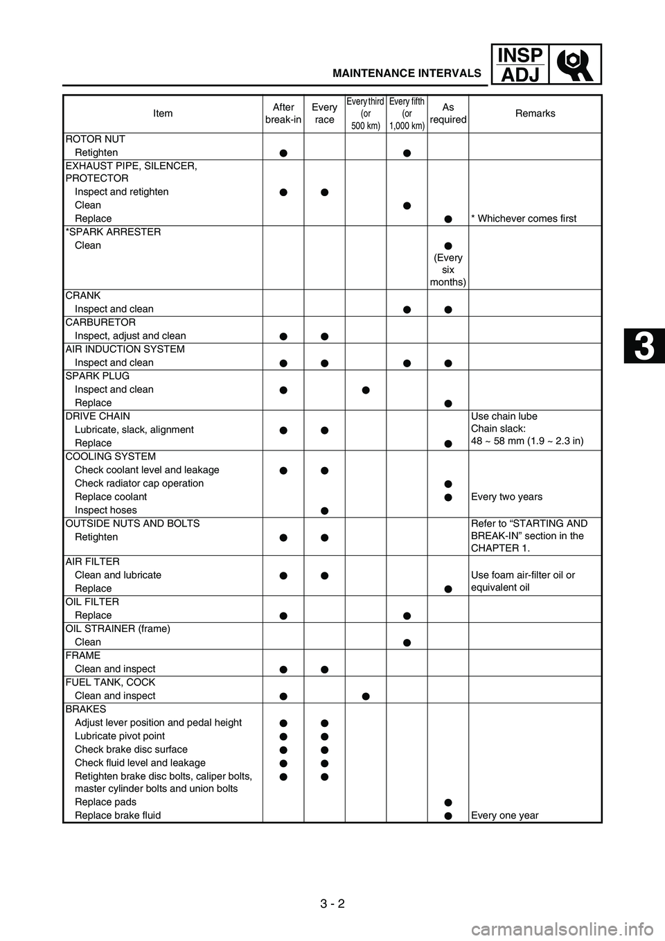
ROTOR NUT
Retighten
EXHAUST PIPE, SILENCER,
PROTECTOR
Inspect and retighten
Clean
Replace* Whichever comes first
*SPARK ARRESTER
Clean
(Every
six
months)
CRANK
Inspect and clean
CARBURETOR
Inspect, adjust and clean
AIR INDUCTION SYSTEM
Inspect and clean
SPARK PLUG
Inspect and clean
Replace
DRIVE CHAINUse chain lube
Chain slack:
48 ~ 58 mm (1.9 ~ 2.3 in) Lubricate, slack, alignment
Replace
COOLING SYSTEM
Check coolant level and leakage
Check radiator cap operation
Replace coolantEvery two years
Inspect hoses
OUTSIDE NUTS AND BOLTS Refer to “STARTING AND
BREAK-IN” section in the
CHAPTER 1. Retighten
AIR FILTER
Clean and lubricate Use foam air-filter oil or
equivalent oil
Replace
OIL FILTER
Replace
OIL STRAINER (frame)
Clean
FRAME
Clean and inspect
FUEL TANK, COCK
Clean and inspect
BRAKES
Adjust lever position and pedal height
Lubricate pivot point
Check brake disc surface
Check fluid level and leakage
Retighten brake disc bolts, caliper bolts,
master cylinder bolts and union bolts
Replace pads
Replace brake fluid Every one yearItemAfter
break-inEvery
race
Every third
(or
500 km)Every fifth
(or
1,000 km)As
requiredRemarks
1
2
3
4
5
6
7
Page 210 of 900

3 - 3
INSP
ADJ
MAINTENANCE INTERVALS
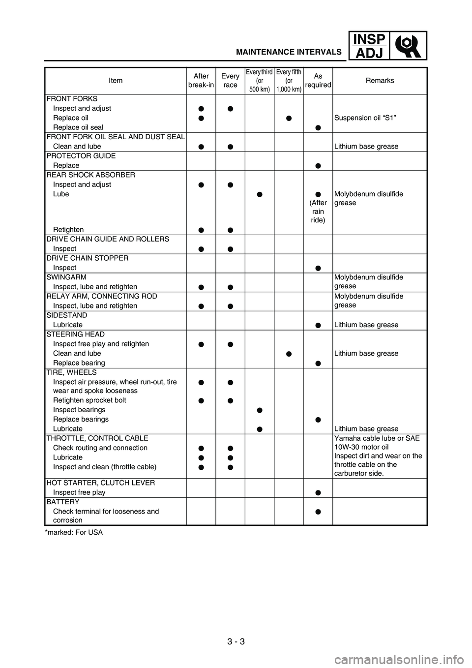
*marked: For USAFRONT FORKS
Inspect and adjust
Replace oilSuspension oil “S1”
Replace oil seal
FRONT FORK OIL SEAL AND DUST SEAL
Clean and lubeLithium base grease
PROTECTOR GUIDE
Replace
REAR SHOCK ABSORBER
Inspect and adjust
Lube
(After
rain
ride)Molybdenum disulfide
grease
Retighten
DRIVE CHAIN GUIDE AND ROLLERS
Inspect
DRIVE CHAIN STOPPER
Inspect
SWINGARMMolybdenum disulfide
grease
Inspect, lube and retighten
RELAY ARM, CONNECTING ROD Molybdenum disulfide
grease
Inspect, lube and retighten
SIDESTAND
LubricateLithium base grease
STEERING HEAD
Inspect free play and retighten
Clean and lubeLithium base grease
Replace bearing
TIRE, WHEELS
Inspect air pressure, wheel run-out, tire
wear and spoke looseness
Retighten sprocket bolt
Inspect bearings
Replace bearings
LubricateLithium base grease
THROTTLE, CONTROL CABLE Yamaha cable lube or SAE
10W-30 motor oil
Inspect dirt and wear on the
throttle cable on the
carburetor side. Check routing and connection
Lubricate
Inspect and clean (throttle cable)
HOT STARTER, CLUTCH LEVER
Inspect free play
BATTERY
Check terminal for looseness and
corrosionItemAfter
break-inEvery
race
Every third
(or
500 km)Every fifth
(or
1,000 km)As
requiredRemarks
Page 256 of 900

3 - 49
INSP
ADJ
VALVE CLEARANCE INSPECTION
AND ADJUSTMENT
NOTE:The valve clearance should be
adjusted when the engine is cool to
the touch.
The piston must be at Top Dead
Center (T.D.C.) on compression
stroke to check or adjust the valve
clearance.
1. Remove:
Seat
Fuel tank
Refer to “SEAT, FUEL TANK
AND SIDE COVERS” section
in the CHAPTER 4.
2. Drain:
Coolant
Refer to “COOLANT
REPLACEMENT” section.
3. Remove:
Right radiator
Refer to “RADIATOR” section
in the CHAPTER 4.
Carburetor
Refer to “CARBURETOR”
section in the CHAPTER 4.
Spark plug
Upper engine bracket
Cylinder head cover
Refer to “CAMSHAFTS” sec-
tion in the CHAPTER 4.
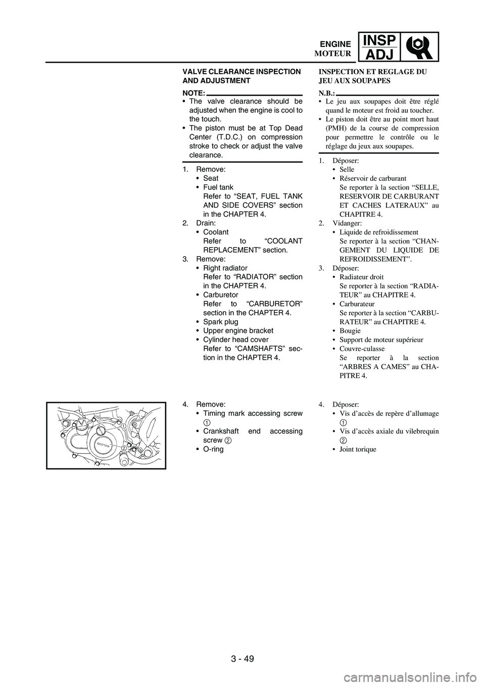
4. Remove:
Timing mark accessing screw
1
Crankshaft end accessing
screw
2
O-ring
INSPECTION ET REGLAGE DU
JEU AUX SOUPAPES
N.B.:
Le jeu aux soupapes doit être réglé
quand le moteur est froid au toucher.
Le piston doit être au point mort haut
(PMH) de la course de compression
pour permettre le contrôle ou le
réglage du jeux aux soupapes.
1. Déposer:
Selle
Réservoir de carburant
Se reporter à la section “SELLE,
RESERVOIR DE CARBURANT
ET CACHES LATERAUX” au
CHAPITRE 4.
2. Vidanger:
Liquide de refroidissement
Se reporter à la section “CHAN-
GEMENT DU LIQUIDE DE
REFROIDISSEMENT”.
3. Déposer:
Radiateur droit
Se reporter à la section “RADIA-
TEUR” au CHAPITRE 4.
Carburateur
Se reporter à la section “CARBU-
RATEUR” au CHAPITRE 4.
Bougie
Support de moteur supérieur
Couvre-culasse
Se reporter à la section
“ARBRES A CAMES” au CHA-
PITRE 4.
4. Déposer:
Vis d’accès de repère d’allumage
1
Vis d’accès axiale du vilebrequin
2
Joint torique
ENGINE
MOTEUR
Page 314 of 900

3 - 107
INSP
ADJ
EC370000
ELECTRICAL
EC371001SPARK PLUG INSPECTION
1. Remove:
Spark plug
2. Inspect:
Electrode
1
Wear/damage
→ Replace.
Insulator color
2
Normal condition is a medium
to light tan color.
Distinctly different color
→
Check the engine condition.
NOTE:When the engine runs for many
hours at low speeds, the spark plug
insulator will become sooty, even if
the engine and carburetor are in
good operating condition.
3. Measure:
Plug gap
a
Use a wire gauge or thickness
gauge.
Out of specification
→ Regap.
4. Clean the plug with a spark plug
cleaner if necessary.
Spark plug gap:
0.7 ~ 0.8 mm
(0.028 ~ 0.031 in)
5. Tighten:
Spark plug
NOTE:Before installing a spark plug,
clean the gasket surface and plug
surface.
Finger-tighten
a the spark plug
before torquing to specification
b.
T R..13 Nm (1.3 m · kg, 9.4 ft · lb)
IGNITION TIMING CHECK
1. Remove:
Timing mark accessing screw
1
PARTIE ELECTRIQUE
CONTROLE DE LA BOUGIE
1. Déposer:
Bougie
2. Contrôler:
Electrode 1
Usure/endommagement → Rem-
placer.
Couleur de l’isolant 2
La couleur normale est une cou-
leur bronze clair ou légèrement
foncé.
Couleur franchement différente
→ Contrôler l’état du moteur.
N.B.:
Lorsque le moteur tourne pendant des
heures à bas régime, l’isolant de la bou-
gie s’encrasse, même si le moteur et le
carburateur sont en bon état de fonction-
nement.
3. Mesurer:
Ecartement a
Utiliser un calibre pour fils ou un
calibre d’épaisseur.
Hors spécifications → Régler.
4. Si nécessaire, nettoyer la bougie à
l’aide d’un nettoie-bougies.
Ecartement des électrodes:
0,7 à 0,8 mm
(0,028 à 0,031 in)
5. Serrer:
Bougie
N.B.:
Avant de monter une bougie, nettoyer
la surface du joint et la surface de la
bougie.
Serrer la bougie à la main a avant de
la serrer au couple correct b.
T R..13 Nm (1,3 m · kg, 9,4 ft · lb)
CONTROLE DE L’AVANCE A
L’ALLUMAGE
1. Déposer:
Vis d’accès de repère d’allumage
1
ELECTRICAL
PARTIE ELECTRIQUE
Page 362 of 900

4 - 21
ENGCARBURETOR
CARBURETOR
9
6
T R..4 Nm (0.4 m •
kg, 2.9 ft • Ib)
T R..2 Nm (0.2 m •
kg, 1.4 ft • Ib)
T R..11 Nm (1.1 m •
kg, 8.0 ft • Ib)
T R..4 Nm (0.4 m •
kg, 2.9 ft • Ib)
T R..3 Nm (0.3 m • kg, 2.2 ft • Ib)
T R..3 Nm (0.3 m • kg, 2.2 ft • Ib)
7
8
5 1
2
64
4
1
3
1
Extent of removal:
1 Carburetor removal
Extent of removal Order Part name Q’ty Remarks
CARBURETOR REMOVAL
Preparation for removal Seat and fuel tank Refer to “SEAT, FUEL TANK AND SIDE COVERS”
section.
1 Clamp 3
2 Throttle position sensor lead coupler 1
3 Throttle cable cover 1
4 Throttle cable 2
5 Clamp (air filter joint) 1 Loosen the screw (air filter joint).
6 Clamp (carburetor joint) 2 Loosen the screws (carburetor joint).
7 Hot starter plunger 1
8 Carburetor assembly 1
9 Carburetor joint 1
1
Page 366 of 900

4 - 25
ENGCARBURETOR
EC468000CARBURETOR DISASSEMBLY
Extent of removal:
1 Carburetor disassembly
Extent of removal Order Part name Q’ty Remarks
CARBURETOR DISASSEMBLY
1 Carburetor breather hose 4
2 Valve lever housing cover 1
3 Screw (throttle shaft) 1
4 Throttle valve 1
5 Needle holder 1
6 Jet needle 1
7 Accelerator pump cover 1
8 Spring 1
9 Diaphragm (accelerator pump) 1
0 Air cut valve cover 1
A Spring (air cut valve) 1
B Diaphragm (air cut valve) 1
C Float chamber 1
D Leak jet 1
1
Page 370 of 900

4 - 29
ENGCARBURETOR
Extent of removal Order Part name Q’ty Remarks
E Float pin 1
F Float 1
G Needle valve 1
H Main jet 1
I Needle jet 1
J Spacer 1
K Pilot jet 1
L Starter jet 1
M Push rod 1 Pull the push rod.
N Throttle shaft assembly 1
O Push rod link lever assembly 1
P Main air jet 1
Q Pilot air jet 1
R Cold starter plunger 1
1
Page 374 of 900

4 - 33
ENGCARBURETOR
HANDLING NOTE
CAUTION:
Do not loosen the screws (throttle
position sensor) 1
except when
changing the throttle position sen-
sor due to failure because it will
cause a drop in engine perfor-
mance.
1
INSPECTION
Carburetor
1. Inspect:
Carburetor body
Contamination
→ Clean.
NOTE:Use a petroleum based solvent for
cleaning. Blow out all passages
and jets with compressed air.
Never use a wire.
2. Inspect:
Main jet
1
Pilot jet
2
Needle jet 3
Starter jet 4
Pilot air jet 5
Leak jet 6
Main air jet 7
Damage → Replace.
Contamination → Clean.
NOTE:Use a petroleum based solvent for
cleaning. Blow out all passages
and jets with compressed air.
Never use a wire.
Needle valve
1. Inspect:
Needle valve 1
Valve seat 2
Grooved wear a → Replace.
Dust b → Clean.
Filter c
Clogged → Clean.
REMARQUES CONCERNANT LA
MANIPULATION
ATTENTION:
Ne pas desserrer les vis (capteur de
position de papillon des gaz) 1 sauf
en cas de remplacement du capteur de
position de papillon des gaz en raison
d’une panne, car cela provoquerait
une baisse des performances du
moteur.
CONTROLE
Carburateur
1. Contrôler:
Corps du carburateur
Encrassé → Nettoyer.
N.B.:
Nettoyer avec un solvant à base de
pétrole. Nettoyer tous les conduits et
gicleurs à l’air comprimé.
Ne jamais utiliser de fil métallique.
2. Contrôler:
Gicleur principal 1
Gicleur de ralenti 2
Gicleur d’aiguille 3
Gicleur de starter 4
Gicleur d’air de ralenti 5
Gicleur de fuite 6
Gicleur d’air principal 7
Endommagement → Remplacer.
Encrassé → Nettoyer.
N.B.:
Nettoyer avec un solvant à base de
pétrole. Nettoyer tous les conduits et
gicleurs à l’air comprimé.
Ne jamais utiliser de fil métallique.
Pointeau
1. Contrôler:
Pointeau 1
Siège de pointeau 2
Usure en creux a → Remplacer.
Poussière b → Nettoyer.
Filtre c
Bouché → Nettoyer.
CARBURATEUR
Page 376 of 900

4 - 35
ENGCARBURETOR
EC464301Throttle valve
1. Check:
Free movement
Stick
→ Repair or replace.
NOTE:Insert the throttle valve
1 into the
carburetor body, and check for free
movement.
EC464401Jet needle
1. Inspect:
Jet needle
1
Bends/wear
→ Replace.
Clip groove
Free play exists/wear
→
Replace.
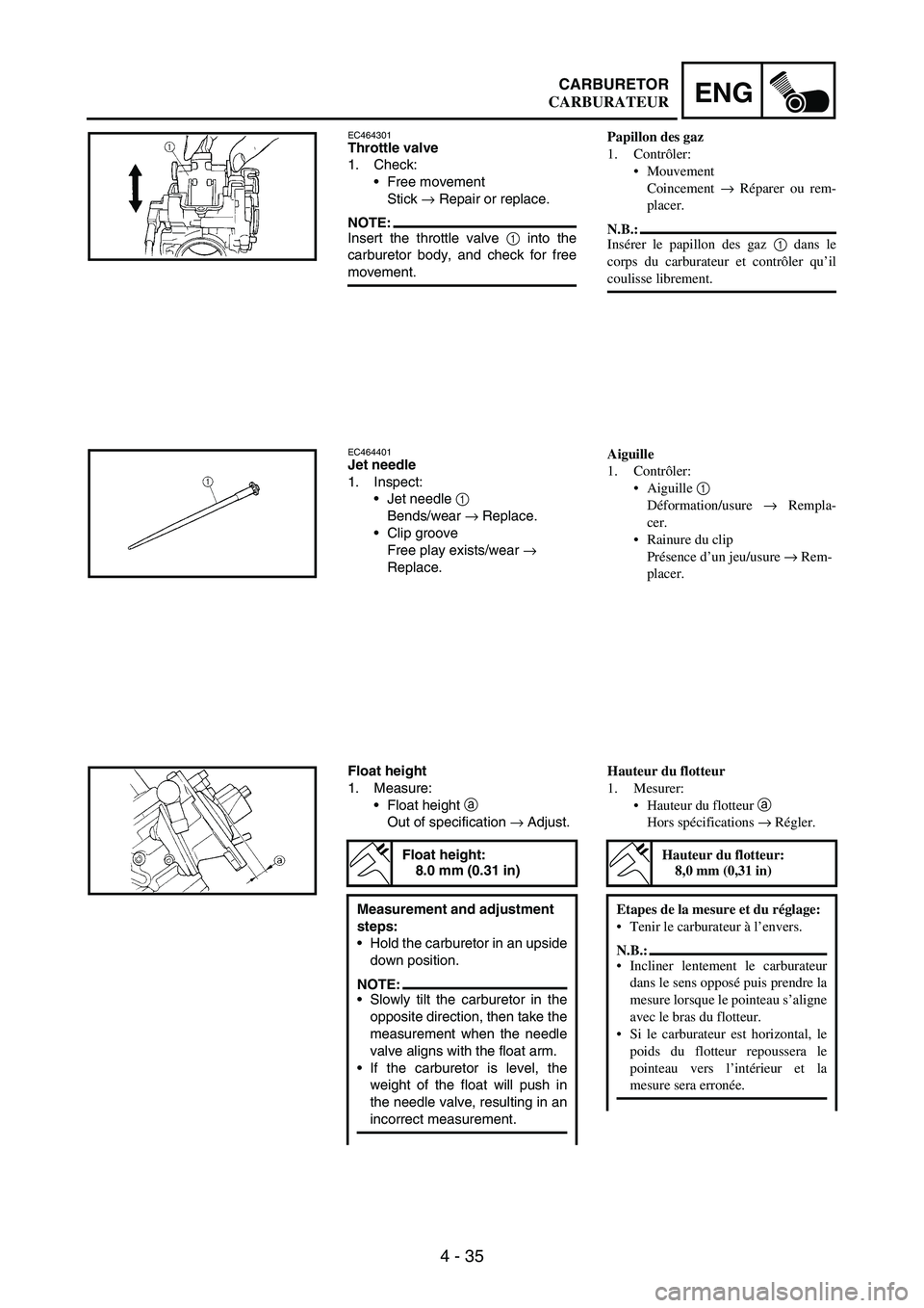
Float height
1. Measure:
Float height
a
Out of specification
→ Adjust.
Float height:
8.0 mm (0.31 in)
Measurement and adjustment
steps:
Hold the carburetor in an upside
down position.
NOTE:Slowly tilt the carburetor in the
opposite direction, then take the
measurement when the needle
valve aligns with the float arm.
If the carburetor is level, the
weight of the float will push in
the needle valve, resulting in an
incorrect measurement.
Papillon des gaz
1. Contrôler:
Mouvement
Coincement → Réparer ou rem-
placer.
N.B.:
Insérer le papillon des gaz 1 dans le
corps du carburateur et contrôler qu’il
coulisse librement.
Aiguille
1. Contrôler:
Aiguille 1
Déformation/usure → Rempla-
cer.
Rainure du clip
Présence d’un jeu/usure → Rem-
placer.
Hauteur du flotteur
1. Mesurer:
Hauteur du flotteur a
Hors spécifications → Régler.
Hauteur du flotteur:
8,0 mm (0,31 in)
Etapes de la mesure et du réglage:
Tenir le carburateur à l’envers.
N.B.:
Incliner lentement le carburateur
dans le sens opposé puis prendre la
mesure lorsque le pointeau s’aligne
avec le bras du flotteur.
Si le carburateur est horizontal, le
poids du flotteur repoussera le
pointeau vers l’intérieur et la
mesure sera erronée.
CARBURATEUR