engine YAMAHA WR 250F 2007 Owners Manual
[x] Cancel search | Manufacturer: YAMAHA, Model Year: 2007, Model line: WR 250F, Model: YAMAHA WR 250F 2007Pages: 912, PDF Size: 23.95 MB
Page 588 of 912
5 - 181
ENGKICK SHAFT AND SHIFT SHAFT
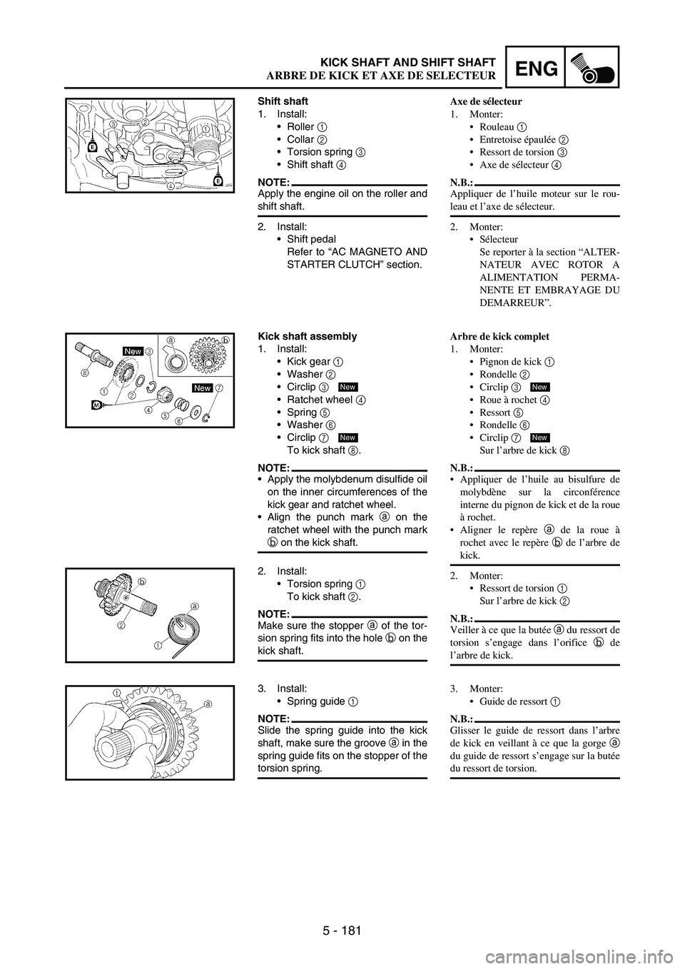
Shift shaft
1. Install:
Roller
1
Collar
2
Torsion spring
3
Shift shaft
4
NOTE:Apply the engine oil on the roller and
shift shaft.
2. Install:
Shift pedal
Refer to “AC MAGNETO AND
STARTER CLUTCH” section.
Kick shaft assembly
1. Install:
Kick gear
1
Washer
2
Circlip
3
Ratchet wheel
4
Spring
5
Washer
6
Circlip
7
To kick shaft
8.
NOTE:Apply the molybdenum disulfide oil
on the inner circumferences of the
kick gear and ratchet wheel.
Align the punch mark
a on the
ratchet wheel with the punch mark
b on the kick shaft.
New
New
2. Install:
Torsion spring
1
To kick shaft
2.
NOTE:Make sure the stopper
a of the tor-
sion spring fits into the hole
b on the
kick shaft.
3. Install:
Spring guide
1
NOTE:Slide the spring guide into the kick
shaft, make sure the groove
a in the
spring guide fits on the stopper of the
torsion spring.
Axe de sélecteur
1. Monter:
Rouleau 1
Entretoise épaulée 2
Ressort de torsion 3
Axe de sélecteur 4
N.B.:
Appliquer de l’huile moteur sur le rou-
leau et l’axe de sélecteur.
2. Monter:
Sélecteur
Se reporter à la section “ALTER-
NATEUR AVEC ROTOR A
ALIMENTATION PERMA-
NENTE ET EMBRAYAGE DU
DEMARREUR”.
Arbre de kick complet
1. Monter:
Pignon de kick 1
Rondelle 2
Circlip 3
Roue à rochet 4
Ressort 5
Rondelle 6
Circlip 7
Sur l’arbre de kick 8
N.B.:
Appliquer de l’huile au bisulfure de
molybdène sur la circonférence
interne du pignon de kick et de la roue
à rochet.
Aligner le repère a de la roue à
rochet avec le repère b de l’arbre de
kick.
2. Monter:
Ressort de torsion 1
Sur l’arbre de kick 2
N.B.:
Veiller à ce que la butée a du ressort de
torsion s’engage dans l’orifice b de
l’arbre de kick.
New
New
3. Monter:
Guide de ressort 1
N.B.:
Glisser le guide de ressort dans l’arbre
de kick en veillant à ce que la gorge a
du guide de ressort s’engage sur la butée
du ressort de torsion.
ARBRE DE KICK ET AXE DE SELECTEUR
Page 590 of 912
5 - 183
ENG
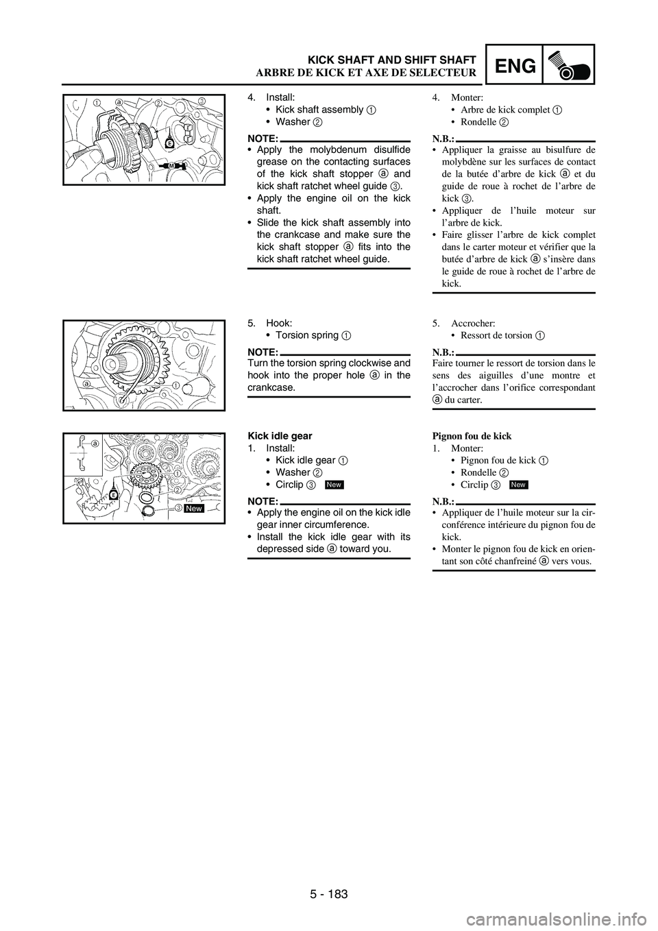
4. Install:
Kick shaft assembly
1
Washer
2
NOTE:Apply the molybdenum disulfide
grease on the contacting surfaces
of the kick shaft stopper
a and
kick shaft ratchet wheel guide
3.
Apply the engine oil on the kick
shaft.
Slide the kick shaft assembly into
the crankcase and make sure the
kick shaft stopper
a fits into the
kick shaft ratchet wheel guide.
5. Hook:
Torsion spring
1
NOTE:Turn the torsion spring clockwise and
hook into the proper hole
a in the
crankcase.
Kick idle gear
1. Install:
Kick idle gear
1
Washer
2
Circlip
3
NOTE:Apply the engine oil on the kick idle
gear inner circumference.
Install the kick idle gear with its
depressed side
a toward you.
New
4. Monter:
Arbre de kick complet 1
Rondelle 2
N.B.:
Appliquer la graisse au bisulfure de
molybdène sur les surfaces de contact
de la butée d’arbre de kick a et du
guide de roue à rochet de l’arbre de
kick 3.
Appliquer de l’huile moteur sur
l’arbre de kick.
Faire glisser l’arbre de kick complet
dans le carter moteur et vérifier que la
butée d’arbre de kick a s’insère dans
le guide de roue à rochet de l’arbre de
kick.
5. Accrocher:
Ressort de torsion 1
N.B.:
Faire tourner le ressort de torsion dans le
sens des aiguilles d’une montre et
l’accrocher dans l’orifice correspondant
a du carter.
Pignon fou de kick
1. Monter:
Pignon fou de kick 1
Rondelle 2
Circlip 3
N.B.:
Appliquer de l’huile moteur sur la cir-
conférence intérieure du pignon fou de
kick.
Monter le pignon fou de kick en orien-
tant son côté chanfreiné a vers vous.
New
KICK SHAFT AND SHIFT SHAFT
ARBRE DE KICK ET AXE DE SELECTEUR
Page 592 of 912
5 - 185
ENGAC MAGNETO AND STARTER CLUTCH
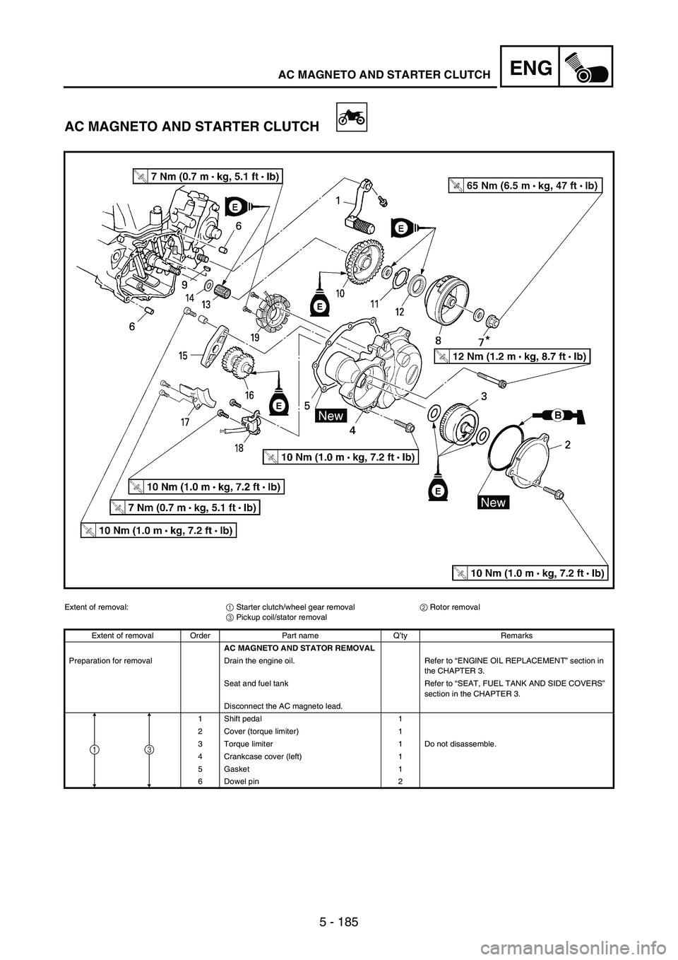
AC MAGNETO AND STARTER CLUTCH
Extent of removal:
1 Starter clutch/wheel gear removal
2 Rotor removal
3 Pickup coil/stator removal
Extent of removal Order Part name Q’ty Remarks
AC MAGNETO AND STATOR REMOVAL
Preparation for removal Drain the engine oil. Refer to “ENGINE OIL REPLACEMENT” section in
the CHAPTER 3.
Seat and fuel tank Refer to “SEAT, FUEL TANK AND SIDE COVERS”
section in the CHAPTER 3.
Disconnect the AC magneto lead.
1 Shift pedal 1
2 Cover (torque limiter) 1
3 Torque limiter 1 Do not disassemble.
4 Crankcase cover (left) 1
5 Gasket 1
6 Dowel pin 2
31
Page 606 of 912
5 - 199
ENGAC MAGNETO AND STARTER CLUTCH
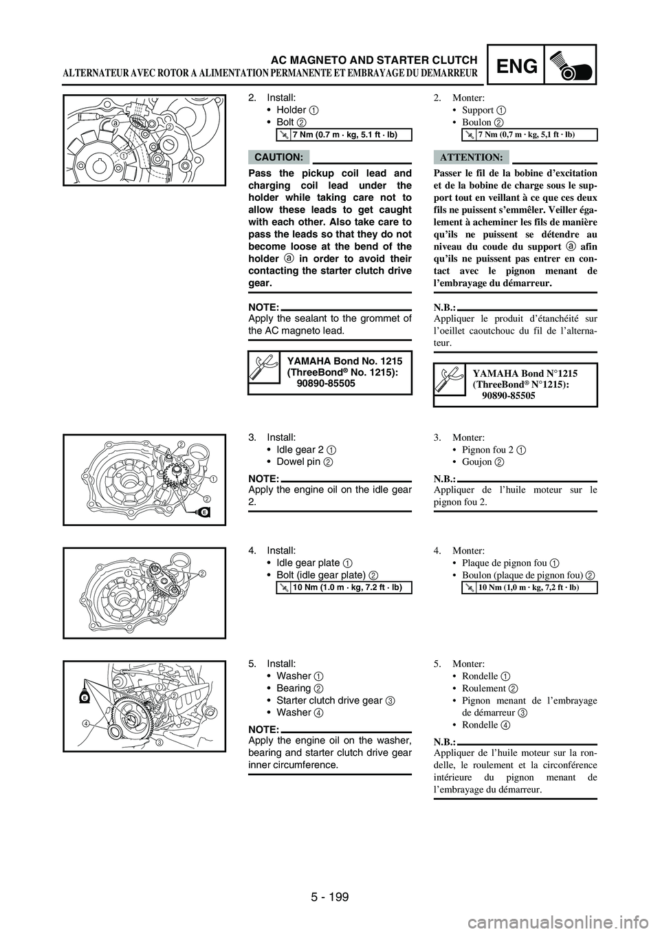
2. Install:
Holder
1
Bolt
2
CAUTION:
Pass the pickup coil lead and
charging coil lead under the
holder while taking care not to
allow these leads to get caught
with each other. Also take care to
pass the leads so that they do not
become loose at the bend of the
holder a
in order to avoid their
contacting the starter clutch drive
gear.
NOTE:Apply the sealant to the grommet of
the AC magneto lead.
T R..7 Nm (0.7 m · kg, 5.1 ft · lb)
YAMAHA Bond No. 1215
(ThreeBond® No. 1215):
90890-85505
12 a
3. Install:
Idle gear 2
1
Dowel pin
2
NOTE:Apply the engine oil on the idle gear
2.21
2
E
4. Install:
Idle gear plate
1
Bolt (idle gear plate)
2
T R..10 Nm (1.0 m · kg, 7.2 ft · lb)
21
5. Install:
Washer
1
Bearing
2
Starter clutch drive gear
3
Washer 4
NOTE:Apply the engine oil on the washer,
bearing and starter clutch drive gear
inner circumference.
E12
3
4
2. Monter:
Support 1
Boulon 2
ATTENTION:
Passer le fil de la bobine d’excitation
et de la bobine de charge sous le sup-
port tout en veillant à ce que ces deux
fils ne puissent s’emmêler. Veiller éga-
lement à acheminer les fils de manière
qu’ils ne puissent se détendre au
niveau du coude du support a afin
qu’ils ne puissent pas entrer en con-
tact avec le pignon menant de
l’embrayage du démarreur.
N.B.:
Appliquer le produit d’étanchéité sur
l’oeillet caoutchouc du fil de l’alterna-
teur.
T R..7 Nm (0,7 m · kg, 5,1 ft · lb)
YAMAHA Bond N°1215
(ThreeBond® N°1215):
90890-85505
3. Monter:
Pignon fou 2 1
Goujon 2
N.B.:
Appliquer de l’huile moteur sur le
pignon fou 2.
4. Monter:
Plaque de pignon fou 1
Boulon (plaque de pignon fou) 2
T R..10 Nm (1,0 m · kg, 7,2 ft · lb)
5. Monter:
Rondelle 1
Roulement 2
Pignon menant de l’embrayage
de démarreur 3
Rondelle 4
N.B.:
Appliquer de l’huile moteur sur la ron-
delle, le roulement et la circonférence
intérieure du pignon menant de
l’embrayage du démarreur.
ALTERNATEUR AVEC ROTOR A ALIMENTATION PERMANENTE ET EMBRAYAGE DU DEMARREUR
Page 610 of 912

5 - 203
ENGAC MAGNETO AND STARTER CLUTCH
9. Install:
Washer (rotor)
Nut (rotor)
1
Use the sheave holder
2.
NOTE:Tighten the rotor nut to 65 Nm
(6.5 mkg, 47 ftlb), loosen and
retighten the rotor nut to 65 Nm
(6.5 m kg, 47 ft lb).
T R..65 Nm (6.5 m · kg, 47 ft · lb)
Sheave holder:
YS-1880-A/
90890-01701
2
1
10. Install:
Dowel pin
Gasket [crankcase cover (left)]
Crankcase cover (left)
1
Bolt [crankcase cover (left)]
2
Bolt [crankcase cover (left)]
3
NOTE:Tighten the bolts in stage, using a
crisscross pattern.
T R..10 Nm (1.0 m · kg, 7.2 ft · lb)
T R..12 Nm (1.2 m · kg, 8.7 ft · lb)
32
3
2
1New
11. Install:
Washer 1
Torque limiter 2
Washer 3
NOTE:Apply the engine oil to the shaft and
washers.
E
1
2
3
12. Install:
O-ring
Cover (idle gear 1) 1
Bolt 2
NOTE:Apply the lithium soap base grease
on the O-ring.
Install the cover (idle gear 1) with
its mark a facing upward.
T R..10 Nm (1.0 m · kg, 7.2 ft · lb)
a
2
1
2New
9. Monter:
Rondelle (rotor)
Ecrou (rotor) 1
Utiliser la clé à sangle 2.
N.B.:
Serrer l’écrou du rotor à 65 Nm
(6,5 mkg, 47 ftlb), desserrer puis
resserrer l’écrou du rotor à 65 Nm
(6,5 m kg, 47 ft lb).
T R..65 Nm (6,5 m · kg, 47 ft · lb)
Clé à sangle:
YS-1880-A/90890-01701
10. Monter:
Goujon
Joint [couvercle de carter (gauche)]
Couvercle de carter (gauche) 1
Boulon
[couvercle de carter (gauche)] 2
Boulon
[couvercle de carter (gauche)] 3
N.B.:
Serrer les boulons par étapes et en procé-
dant en croix.
T R..10 Nm (1,0 m · kg, 7,2 ft · lb)
T R..12 Nm (1,2 m · kg, 8,7 ft · lb)
New
11. Monter:
Rondelle 1
Limiteur de couple 2
Rondelle 3
N.B.:
Appliquer de l’huile moteur sur l’arbre
et les rondelles.
12. Monter:
Joint torique
Couvercle (pignon fou 1) 1
Boulon 2
N.B.:
Appliquer de la graisse à savon de
lithium sur le joint torique.
Monter le couvercle (pignon fou 1) en
orientant son repère a vers le haut.
T R..10 Nm (1,0 m · kg, 7,2 ft · lb)
New
ALTERNATEUR AVEC ROTOR A ALIMENTATION PERMANENTE ET EMBRAYAGE DU DEMARREUR
Page 614 of 912
5 - 207
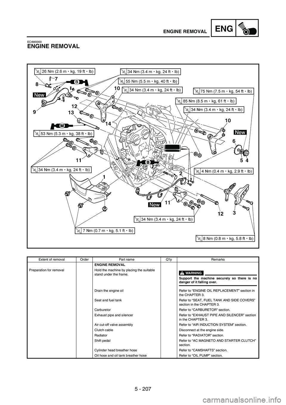
ENGENGINE REMOVAL
EC4M0000
ENGINE REMOVAL
Extent of removal Order Part name Q’ty Remarks
ENGINE REMOVAL
Preparation for removal Hold the machine by placing the suitable
stand under the frame.
WARNING
Support the machine securely so there is nodanger of it falling over.
Drain the engine oil Refer to “ENGINE OIL REPLACEMENT” section in
the CHAPTER 3.
Seat and fuel tank Refer to “SEAT, FUEL TANK AND SIDE COVERS”
section in the CHAPTER 3.
Carburetor Refer to “CARBURETOR” section.
Exhaust pipe and silencer Refer to “EXHAUST PIPE AND SILENCER” section
in the CHAPTER 3.
Air cut-off valve assembly Refer to “AIR INDUCTION SYSTEM” section.
Clutch cable Disconnect at the engine side.
Radiator Refer to “RADIATOR” section.
Shift pedal Refer to “AC MAGNETO AND STARTER CLUTCH”
section.
Cylinder head breather hose Refer to “CAMSHAFTS” section.
Oil hose and oil tank breather hose Refer to “OIL PUMP” section.
Page 618 of 912
5 - 211
ENGENGINE REMOVAL
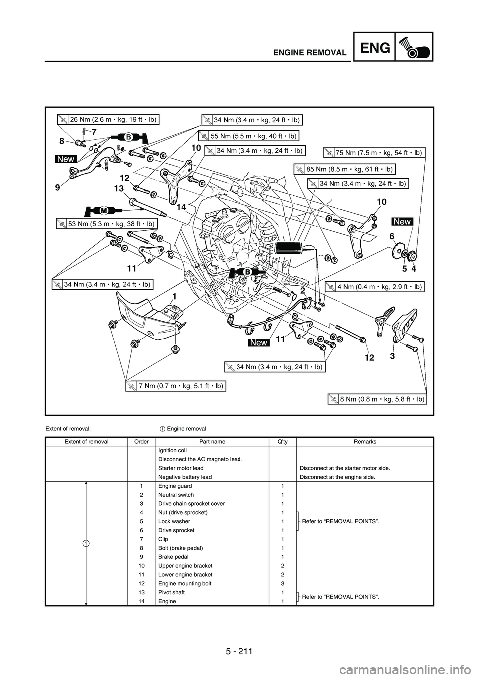
Extent of removal:
1 Engine removal
Extent of removal Order Part name Q’ty Remarks
Ignition coil
Disconnect the AC magneto lead.
Starter motor lead Disconnect at the starter motor side.
Negative battery lead Disconnect at the engine side.
1 Engine guard 1
2 Neutral switch 1
3 Drive chain sprocket cover 1
4 Nut (drive sprocket) 1
Refer to “REMOVAL POINTS”. 5 Lock washer 1
6 Drive sprocket 1
7 Clip 1
8 Bolt (brake pedal) 1
9 Brake pedal 1
10 Upper engine bracket 2
11 Lower engine bracket 2
12 Engine mounting bolt 3
13 Pivot shaft 1
Refer to “REMOVAL POINTS”.
14 Engine 1
1
Page 622 of 912
5 - 215
ENGENGINE REMOVAL
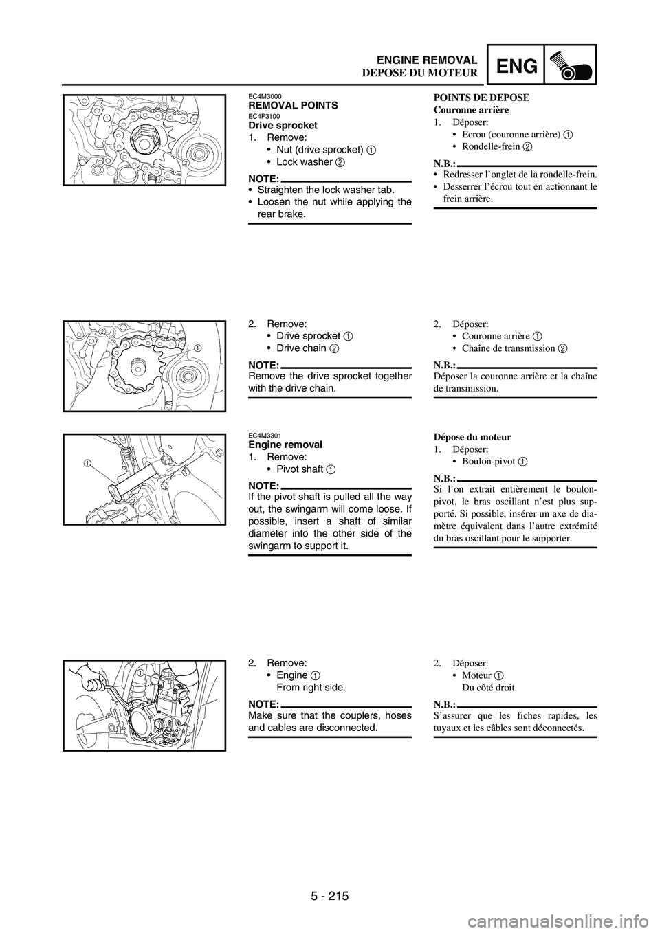
EC4M3000REMOVAL POINTSEC4F3100Drive sprocket
1. Remove:
Nut (drive sprocket)
1
Lock washer
2
NOTE:Straighten the lock washer tab.
Loosen the nut while applying the
rear brake.
2. Remove:
Drive sprocket
1
Drive chain
2
NOTE:Remove the drive sprocket together
with the drive chain.
EC4M3301Engine removal
1. Remove:
Pivot shaft
1
NOTE:If the pivot shaft is pulled all the way
out, the swingarm will come loose. If
possible, insert a shaft of similar
diameter into the other side of the
swingarm to support it.
2. Remove:
Engine
1
From right side.
NOTE:Make sure that the couplers, hoses
and cables are disconnected.
1
POINTS DE DEPOSE
Couronne arrière
1. Déposer:
Ecrou (couronne arrière) 1
Rondelle-frein 2
N.B.:
Redresser l’onglet de la rondelle-frein.
Desserrer l’écrou tout en actionnant le
frein arrière.
2. Déposer:
Couronne arrière 1
Chaîne de transmission 2
N.B.:
Déposer la couronne arrière et la chaîne
de transmission.
Dépose du moteur
1. Déposer:
Boulon-pivot 1
N.B.:
Si l’on extrait entièrement le boulon-
pivot, le bras oscillant n’est plus sup-
porté. Si possible, insérer un axe de dia-
mètre équivalent dans l’autre extrémité
du bras oscillant pour le supporter.
2. Déposer:
Moteur 1
Du côté droit.
N.B.:
S’assurer que les fiches rapides, les
tuyaux et les câbles sont déconnectés.
DEPOSE DU MOTEUR
Page 624 of 912
5 - 217
ENGENGINE REMOVAL
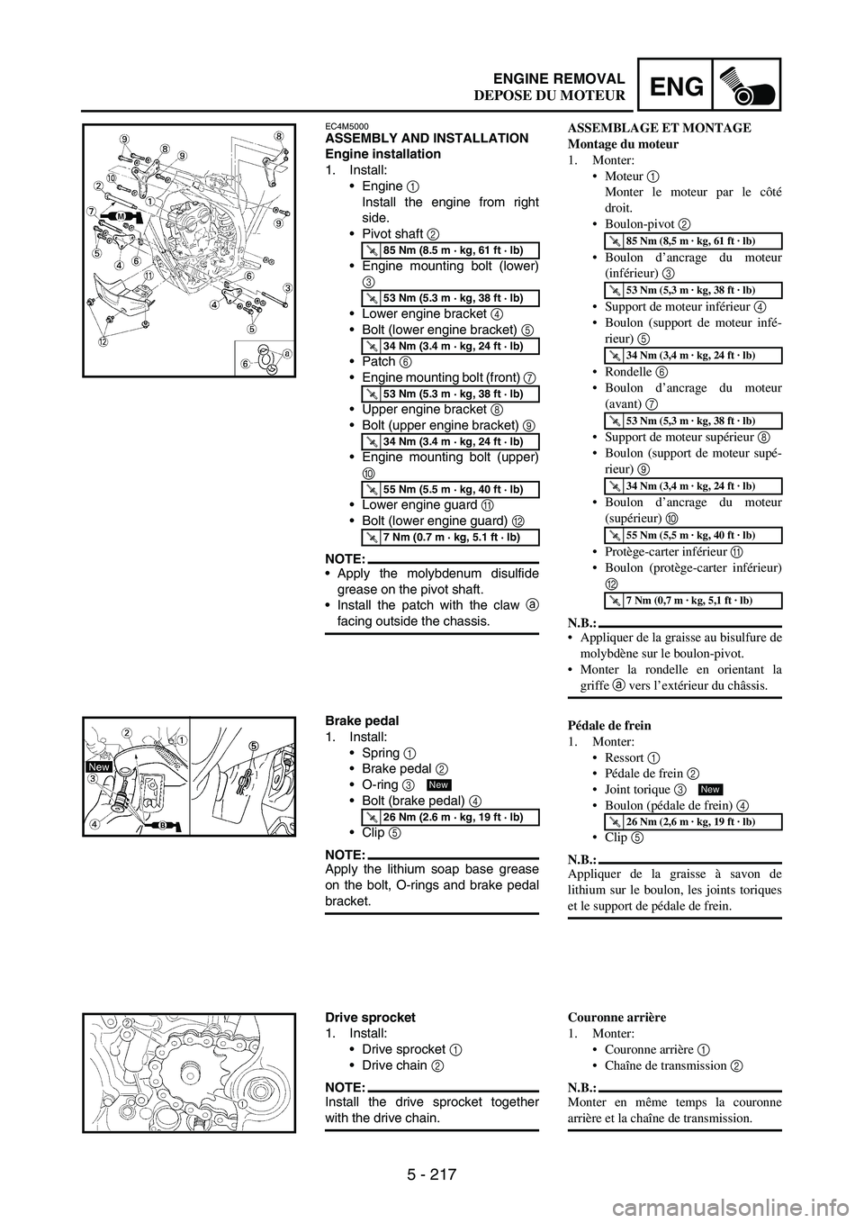
EC4M5000ASSEMBLY AND INSTALLATION
Engine installation
1. Install:
Engine
1
Install the engine from right
side.
Pivot shaft
2
Engine mounting bolt (lower)
3
Lower engine bracket
4
Bolt (lower engine bracket)
5
Patch
6
Engine mounting bolt (front)
7
Upper engine bracket
8
Bolt (upper engine bracket)
9
Engine mounting bolt (upper)
0
Lower engine guard
A
Bolt (lower engine guard)
B
NOTE:Apply the molybdenum disulfide
grease on the pivot shaft.
Install the patch with the claw
a
facing outside the chassis.
T R..85 Nm (8.5 m · kg, 61 ft · lb)
T R..53 Nm (5.3 m · kg, 38 ft · lb)
T R..34 Nm (3.4 m · kg, 24 ft · lb)
T R..53 Nm (5.3 m · kg, 38 ft · lb)
T R..34 Nm (3.4 m · kg, 24 ft · lb)
T R..55 Nm (5.5 m · kg, 40 ft · lb)
T R..7 Nm (0.7 m · kg, 5.1 ft · lb)
Brake pedal
1. Install:
Spring
1
Brake pedal
2
O-ring
3
Bolt (brake pedal)
4
Clip
5
NOTE:Apply the lithium soap base grease
on the bolt, O-rings and brake pedal
bracket.
T R..26 Nm (2.6 m · kg, 19 ft · lb)
New
Drive sprocket
1. Install:
Drive sprocket
1
Drive chain
2
NOTE:Install the drive sprocket together
with the drive chain.
ASSEMBLAGE ET MONTAGE
Montage du moteur
1. Monter:
Moteur 1
Monter le moteur par le côté
droit.
Boulon-pivot 2
Boulon d’ancrage du moteur
(inférieur) 3
Support de moteur inférieur 4
Boulon (support de moteur infé-
rieur) 5
Rondelle 6
Boulon d’ancrage du moteur
(avant) 7
Support de moteur supérieur 8
Boulon (support de moteur supé-
rieur) 9
Boulon d’ancrage du moteur
(supérieur) 0
Protège-carter inférieur A
Boulon (protège-carter inférieur)
B
N.B.:
Appliquer de la graisse au bisulfure de
molybdène sur le boulon-pivot.
Monter la rondelle en orientant la
griffe a vers l’extérieur du châssis.
Pédale de frein
1. Monter:
Ressort 1
Pédale de frein 2
Joint torique 3
Boulon (pédale de frein) 4
Clip 5
N.B.:
Appliquer de la graisse à savon de
lithium sur le boulon, les joints toriques
et le support de pédale de frein.
T R..85 Nm (8,5 m · kg, 61 ft · lb)
T R..53 Nm (5,3 m · kg, 38 ft · lb)
T R..34 Nm (3,4 m · kg, 24 ft · lb)
T R..53 Nm (5,3 m · kg, 38 ft · lb)
T R..34 Nm (3,4 m · kg, 24 ft · lb)
T R..55 Nm (5,5 m · kg, 40 ft · lb)
T R..7 Nm (0,7 m · kg, 5,1 ft · lb)
T R..26 Nm (2,6 m · kg, 19 ft · lb)
New
Couronne arrière
1. Monter:
Couronne arrière 1
Chaîne de transmission 2
N.B.:
Monter en même temps la couronne
arrière et la chaîne de transmission.
DEPOSE DU MOTEUR
Page 626 of 912
5 - 219
ENGENGINE REMOVAL
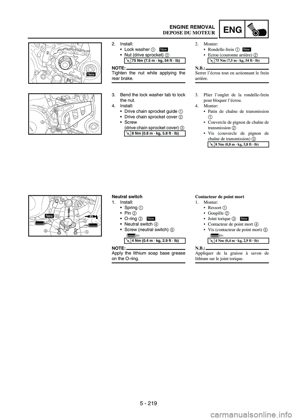
2. Install:
Lock washer
1
Nut (drive sprocket)
2
NOTE:Tighten the nut while applying the
rear brake.
T R..75 Nm (7.5 m · kg, 54 ft · lb)
New
3. Bend the lock washer tab to lock
the nut.
4. Install:
Drive chain sprocket guide
1
Drive chain sprocket cover
2
Screw
(drive chain sprocket cover)
3
T R..8 Nm (0.8 m · kg, 5.8 ft · lb)
Neutral switch
1. Install:
Spring
1
Pin
2
O-ring
3
Neutral switch
4
Screw (neutral switch)
5
NOTE:Apply the lithium soap base grease
on the O-ring.
T R..4 Nm (0.4 m · kg, 2.9 ft · lb)
New
2. Monter:
Rondelle-frein 1
Ecrou (couronne arrière) 2
N.B.:
Serrer l’écrou tout en actionnant le frein
arrière.
T R..75 Nm (7,5 m · kg, 54 ft · lb)
New
3. Plier l’onglet de la rondelle-frein
pour bloquer l’écrou.
4. Monter:
Patin de chaîne de transmission
1
Couvercle de pignon de chaîne de
transmission 2
Vis (couvercle de pignon de
chaîne de transmission) 3
T R..8 Nm (0,8 m · kg, 5,8 ft · lb)
Contacteur de point mort
1. Monter:
Ressort 1
Goupille 2
Joint torique 3
Contacteur de point mort 4
Vis (contacteur de point mort) 5
N.B.:
Appliquer de la graisse à savon de
lithium sur le joint torique.
T R..4 Nm (0,4 m · kg, 2,9 ft · lb)
New
DEPOSE DU MOTEUR