tow YAMAHA WR 250F 2007 User Guide
[x] Cancel search | Manufacturer: YAMAHA, Model Year: 2007, Model line: WR 250F, Model: YAMAHA WR 250F 2007Pages: 912, PDF Size: 23.95 MB
Page 380 of 912

4 - 21
TUNSETTING
EC720000
CHASSIS
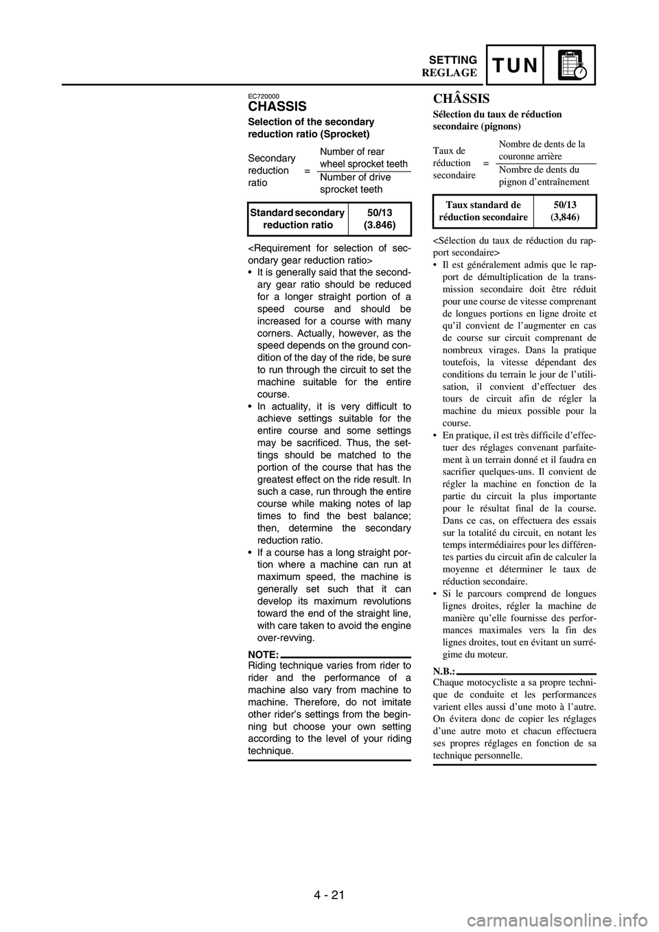
Selection of the secondary
reduction ratio (Sprocket)
It is generally said that the second-
ary gear ratio should be reduced
for a longer straight portion of a
speed course and should be
increased for a course with many
corners. Actually, however, as the
speed depends on the ground con-
dition of the day of the ride, be sure
to run through the circuit to set the
machine suitable for the entire
course.
In actuality, it is very difficult to
achieve settings suitable for the
entire course and some settings
may be sacrificed. Thus, the set-
tings should be matched to the
portion of the course that has the
greatest effect on the ride result. In
such a case, run through the entire
course while making notes of lap
times to find the best balance;
then, determine the secondary
reduction ratio.
If a course has a long straight por-
tion where a machine can run at
maximum speed, the machine is
generally set such that it can
develop its maximum revolutions
toward the end of the straight line,
with care taken to avoid the engine
over-revving.
NOTE:Riding technique varies from rider to
rider and the performance of a
machine also vary from machine to
machine. Therefore, do not imitate
other rider’s settings from the begin-
ning but choose your own setting
according to the level of your riding
technique. Secondary
reduction
ratio=
Number of rear
wheel sprocket teeth
Number of drive
sprocket teeth
Standard secondary
reduction ratio50/13
(3.846)
CHÂSSIS
Sélection du taux de réduction
secondaire (pignons)
Il est généralement admis que le rap-
port de démultiplication de la trans-
mission secondaire doit être réduit
pour une course de vitesse comprenant
de longues portions en ligne droite et
qu’il convient de l’augmenter en cas
de course sur circuit comprenant de
nombreux virages. Dans la pratique
toutefois, la vitesse dépendant des
conditions du terrain le jour de l’utili-
sation, il convient d’effectuer des
tours de circuit afin de régler la
machine du mieux possible pour la
course.
En pratique, il est très difficile d’effec-
tuer des réglages convenant parfaite-
ment à un terrain donné et il faudra en
sacrifier quelques-uns. Il convient de
régler la machine en fonction de la
partie du circuit la plus importante
pour le résultat final de la course.
Dans ce cas, on effectuera des essais
sur la totalité du circuit, en notant les
temps intermédiaires pour les différen-
tes parties du circuit afin de calculer la
moyenne et déterminer le taux de
réduction secondaire.
Si le parcours comprend de longues
lignes droites, régler la machine de
manière qu’elle fournisse des perfor-
mances maximales vers la fin des
lignes droites, tout en évitant un surré-
gime du moteur.
N.B.:
Chaque motocycliste a sa propre techni-
que de conduite et les performances
varient elles aussi d’une moto à l’autre.
On évitera donc de copier les réglages
d’une autre moto et chacun effectuera
ses propres réglages en fonction de sa
technique personnelle. Taux de
réduction
secondaire=
Nombre de dents de la
couronne arrière
Nombre de dents du
pignon d’entraînement
Taux standard de
réduction secondaire50/13
(3,846)
REGLAGE
Page 398 of 912

4 - 39
TUNSETTING
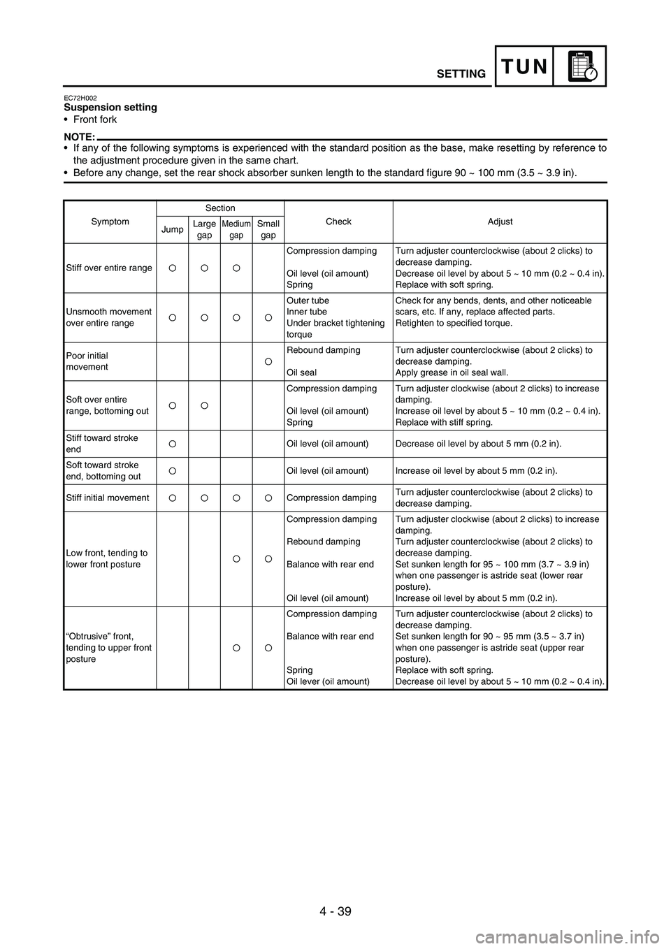
EC72H002Suspension setting
Front fork
NOTE:If any of the following symptoms is experienced with the standard position as the base, make resetting by reference to
the adjustment procedure given in the same chart.
Before any change, set the rear shock absorber sunken length to the standard figure 90 ~ 100 mm (3.5 ~ 3.9 in).
SymptomSection
Check Adjust
JumpLarge
gapMedium
gapSmall
gap
Stiff over entire rangeCompression damping
Oil level (oil amount)
SpringTurn adjuster counterclockwise (about 2 clicks) to
decrease damping.
Decrease oil level by about 5 ~ 10 mm (0.2 ~ 0.4 in).
Replace with soft spring.
Unsmooth movement
over entire rangeOuter tube
Inner tube
Under bracket tightening
torqueCheck for any bends, dents, and other noticeable
scars, etc. If any, replace affected parts.
Retighten to specified torque.
Poor initial
movementRebound damping
Oil sealTurn adjuster counterclockwise (about 2 clicks) to
decrease damping.
Apply grease in oil seal wall.
Soft over entire
range, bottoming outCompression damping
Oil level (oil amount)
SpringTurn adjuster clockwise (about 2 clicks) to increase
damping.
Increase oil level by about 5 ~ 10 mm (0.2 ~ 0.4 in).
Replace with stiff spring.
Stiff toward stroke
endOil level (oil amount) Decrease oil level by about 5 mm (0.2 in).
Soft toward stroke
end, bottoming outOil level (oil amount) Increase oil level by about 5 mm (0.2 in).
Stiff initial movement Compression dampingTurn adjuster counterclockwise (about 2 clicks) to
decrease damping.
Low front, tending to
lower front postureCompression damping
Rebound damping
Balance with rear end
Oil level (oil amount)Turn adjuster clockwise (about 2 clicks) to increase
damping.
Turn adjuster counterclockwise (about 2 clicks) to
decrease damping.
Set sunken length for 95 ~ 100 mm (3.7 ~ 3.9 in)
when one passenger is astride seat (lower rear
posture).
Increase oil level by about 5 mm (0.2 in).
“Obtrusive” front,
tending to upper front
postureCompression damping
Balance with rear end
Spring
Oil lever (oil amount)Turn adjuster counterclockwise (about 2 clicks) to
decrease damping.
Set sunken length for 90 ~ 95 mm (3.5 ~ 3.7 in)
when one passenger is astride seat (upper rear
posture).
Replace with soft spring.
Decrease oil level by about 5 ~ 10 mm (0.2 ~ 0.4 in).
Page 412 of 912

5 - 5
ENGRADIATOR
EC456000HANDLING NOTE
WARNING
Do not remove the radiator cap
when the engine and radiator are
hot. Scalding hot fluid and steam
may be blown out under pressure,
which could cause serious injury.
When the engine has cooled, open
the radiator cap by the following
procedure:
Place a thick rag, like a towel, over
the radiator cap, slowly rotate the
cap counterclockwise to the
detent. This procedure allows any
residual pressure to escape. When
the hissing sound has stopped,
press down on the cap while turn-
ing counterclockwise and remove
it.
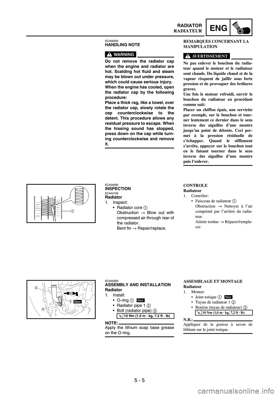
EC454000INSPECTIONEC444100Radiator
1. Inspect:
Radiator core
1
Obstruction
→ Blow out with
compressed air through rear of
the radiator.
Bent fin
→ Repair/replace.
EC455000ASSEMBLY AND INSTALLATION
Radiator
1. Install:
O-ring
1
Radiator pipe 1
2
Bolt (radiator pipe)
3
NOTE:Apply the lithium soap base grease
on the O-ring.
T R..10 Nm (1.0 m · kg, 7.2 ft · lb)
New
REMARQUES CONCERNANT LA
MANIPULATION
AVERTISSEMENT
Ne pas enlever le bouchon du radia-
teur quand le moteur et le radiateur
sont chauds. Du liquide chaud et de la
vapeur risquent de jaillir sous forte
pression et de provoquer des brûlures
graves.
Une fois le moteur refroidi, ouvrir le
bouchon du radiateur en procédant
comme suit:
Placer un chiffon épais, une serviette
par exemple, sur le bouchon et tour-
ner lentement ce dernier dans le sens
inverse des aiguilles d’une montre
jusqu’au point de détente. Ceci per-
met à la pression résiduelle de
s’échapper. Quand le sifflement
s’arrête, appuyer sur le bouchon tout
en le faisant tourner dans le sens
inverse des aiguilles d’une montre
puis l’enlever.
CONTROLE
Radiateur
1. Contrôler:
Faisceau de radiateur 1
Obstruction → Nettoyer à l’air
comprimé par l’arrière du radia-
teur.
Ailette tordue → Réparer/rempla-
cer.
ASSEMBLAGE ET MONTAGE
Radiateur
1. Monter:
Joint torique 1
Tuyau de radiateur 1 2
Boulon (tuyau de radiateur) 3
N.B.:
Appliquer de la graisse à savon de
lithium sur le joint torique.
T R..10 Nm (1,0 m · kg, 7,2 ft · lb)
New
RADIATEUR
Page 590 of 912

5 - 183
ENG
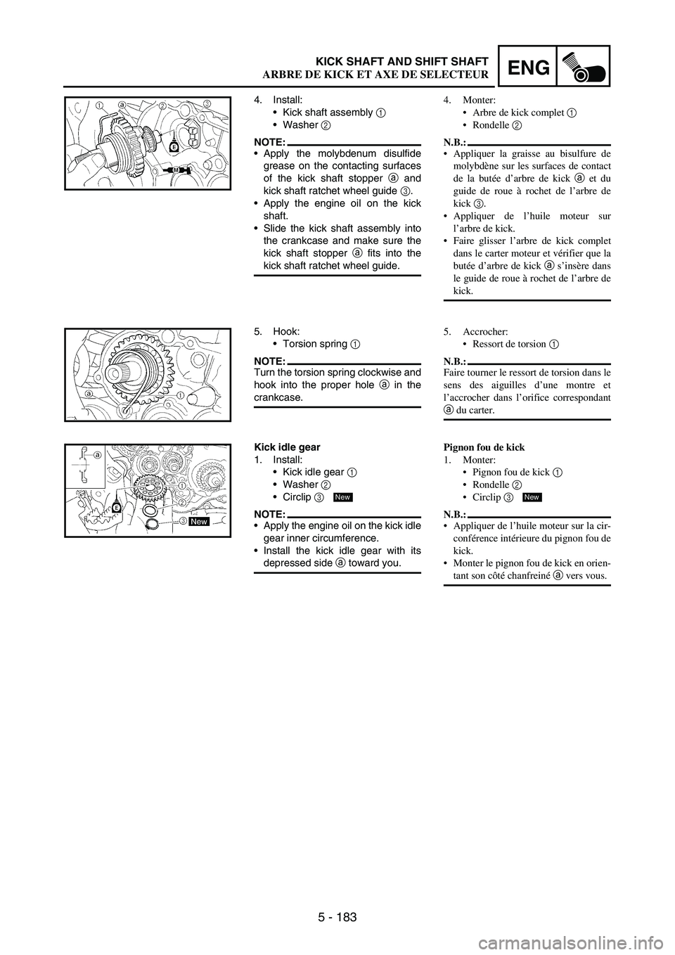
4. Install:
Kick shaft assembly
1
Washer
2
NOTE:Apply the molybdenum disulfide
grease on the contacting surfaces
of the kick shaft stopper
a and
kick shaft ratchet wheel guide
3.
Apply the engine oil on the kick
shaft.
Slide the kick shaft assembly into
the crankcase and make sure the
kick shaft stopper
a fits into the
kick shaft ratchet wheel guide.
5. Hook:
Torsion spring
1
NOTE:Turn the torsion spring clockwise and
hook into the proper hole
a in the
crankcase.
Kick idle gear
1. Install:
Kick idle gear
1
Washer
2
Circlip
3
NOTE:Apply the engine oil on the kick idle
gear inner circumference.
Install the kick idle gear with its
depressed side
a toward you.
New
4. Monter:
Arbre de kick complet 1
Rondelle 2
N.B.:
Appliquer la graisse au bisulfure de
molybdène sur les surfaces de contact
de la butée d’arbre de kick a et du
guide de roue à rochet de l’arbre de
kick 3.
Appliquer de l’huile moteur sur
l’arbre de kick.
Faire glisser l’arbre de kick complet
dans le carter moteur et vérifier que la
butée d’arbre de kick a s’insère dans
le guide de roue à rochet de l’arbre de
kick.
5. Accrocher:
Ressort de torsion 1
N.B.:
Faire tourner le ressort de torsion dans le
sens des aiguilles d’une montre et
l’accrocher dans l’orifice correspondant
a du carter.
Pignon fou de kick
1. Monter:
Pignon fou de kick 1
Rondelle 2
Circlip 3
N.B.:
Appliquer de l’huile moteur sur la cir-
conférence intérieure du pignon fou de
kick.
Monter le pignon fou de kick en orien-
tant son côté chanfreiné a vers vous.
New
KICK SHAFT AND SHIFT SHAFT
ARBRE DE KICK ET AXE DE SELECTEUR